Note: Descriptions are shown in the official language in which they were submitted.
CA 02255790 1998-12-14
LID FOR BEVERAGE CONTAINER
This invention generally relates to covers for use in
combination with beverage containers. More particularly,
this invention relates to lids that have a pivotable cover
for releasably sealing liquids within a beverage container.
Background of the Invention
to Beverage containers having lids are well known in the
art. Generally, beverage containers include a bottom
surface and upward extending walls that terminate at an
opening oppositely disposed from the bottom surface.
Containers of the above mentioned character allow
fluids to be retained therein and accessed through the
opening. Although containers adequately retain liquids, it
has often been desirable to secure liquids within containers
in a manner that isolates the contents. To do so, lids have
often been employed such that the contents of the containers
2o are isolated from the external environment. Sealing the
containers prevents the undesirable escape or spillage of
the retained liquids. Also, a properly secured lid allows
the liquids to be sealed from external contaminates found in
the users environment.
Although containers of the above mentioned sort provide
a mechanism for retaining liquids therein with increased
security, manipulation of the lid is often complex and does
not lend itself to simple actuation. Users who desire
access to the fluid contained within the container are often
so required to manipulate cumbersome mechanisms. Although for
most users, operation of such devices is merely time
consuming. For many users such as disabled, elderly or
CA 02255790 1998-12-14
-2-
juvenile users operation of such devices is exceptionally
complex and may ultimately result in frustrating access to
the contents whatsoever.
In order to overcome the above disadvantages several
lids have been suggested. For instance U.S. Patent No.
4,792,083 to Yassur discloses a drinking tube for use in
combination with a beverage container of the type having a
cover with a sealing tear-out tab which may be pulled to
rupture the closure. Once ruptured, access is provided
1o through the opening to the contents of the container. Such
lids include a drinking tube that is attached to the lid by
a flexible member which biases the tube against the lid.
Once the tear-out tab is removed from the container, the
drinking tube pivots outward for operation by the user.
Although the above mentioned devices address some of
the drawbacks found in beverage containers, they also have
several drawbacks as well. Namely, the device to Yassur is
suggested as being usable only once. The tear-out tab can
only be removed from the lid once. Secondly, once opened,
2o the opening allows communication between the environment and
the liquid retained within the container without the
possibility of reclosure once opened. Therefore, after the
user has actuated the tear-out tab, the user must make use
of the entire contents of the container or else risk
spillage or external contamination. Finally, removing the
liquid through the use of a drinking straw may be desirable
when operated by a single user. Yet, when it is
contemplated that the device is to be used by several
CA 02255790 1998-12-14
-3-
operators, such a mechanism for removal of the liquid from
the container is undesirable and unsanitary.
Other devices have been suggested to advance the art.
For instance, U.S. Patent No. 4,993,603 to Polhemus teaches
food storage containers which include a lid having an open
position and a closed position. When in a closed position,
a plug disposed on the lid is sized to conform with the
opening in the container to provide a seal. When in an open
position, the contents may be poured by tilting the
1o container such that the liquid passes out of the container
and over the pour spout. The underside of the lid has a
generally angular shape with a downwardly extending apex.
While the device taught by Polhemus advances the art,
it too has drawbacks. First, the device provides a single
cap that spans the entire top portion of the container.
Although this arrangement allows the container to be sealed,
the cap to Polhemus is only retained in the closed
configuration by frictional engagement between a bead means
on the plug and a recessed groove on the entire opening of
2o the container. One skilled in the art can best appreciate
that the above device would not be capable of resisting
pressure upon the container caused by a violent impact such
as dropping the container or otherwise jarring the lid since
the bead/groove member must seal the entire top portion of
the container. Other than the bead/groove mechanism there
is no other positive attachment between the lid and the
container. Further, since the cap spans the entire top
portion of the container, the contents may almost
immediately be released once opened.
CA 02255790 1998-12-14
_q_
In addition, the device to Polhemus does not provide
any mechanism for covering the spout. Although such devices
would prevent the fluid retained within the container from
contacting the outside environment, these devices do not
enclose the pour spout from contacting outside contaminates.
Accordingly, any contaminates that may have collected on the
spout while in use may contact the fluid when it is flowed
over the pour spout.
Other various lids have been suggested such as U.S.
1o Patent No. 5, 579, 961 to Zimmerman. Zimmerman teaches a
container top including a rotatable member fitted on a
container having a pour spout. The rotatable member
includes a plug that closes an opening defined by a tubular
wall. The rotatable member is pivoted about a pair of
projection pins that snap into a pair of recesses. The
rotatable member is reciprocally maintained in either an
open position or a closed position by frictional engagement
between a rear skirt on the rotatable member and a cam
surface on the cover.
2o While the device to Zimmerman has advanced the art,
these devices have several shortcomings. First, the cover
to Zimmerman is attached merely by the frictional engagement
between the cap and the container. Secondly, as in the
previous devices, the device to Zimmerman permits contact
between the outside environment and the pour spout.
Thereby, fluids poured over the pour spout are likely to
contact contaminates that have collected on the pour spout.
Finally, the device to Zimmerman is designed to be actuated
by depressing either the forward or rearward portions of the
CA 02255790 1998-12-14
-5-
rotatable member. The pins that attach the container top
are distanced at the outer peripheral surface of the
rotatable member. Although the rotatable member may pivot
about the projection pins, the location of the pins at
alternate outward surfaces of the rotatable member may lead
to undue stresses in the rotatable member. Since the
rotatable member is designed to be actuated by depressing
the rotatable member, stresses realized by the rotatable
member may cause the rotatable member to camber. As a
to result, the rotatable member may either begin to crack or
cause the projecting pins to be broken or otherwise detached
from the rotatable member.
As can be seen from the above further advances would be
desirable in the art. One skilled in the art can best
appreciate that it would be desirable to have a lid which is
capable of reliably retaining a liquid within a beverage
container thus reducing the opportunity of unanticipated
spillage of liquids. It also would be desirable to have a
lid that minimizes undesirable contact of the liquid with
2o environmental contaminates. Further, it would be desirable
to have a cover that secures the liquid within the container
while also being actuatable to release the retained fluid
from the container in a simple and uncomplicated manner.
Finally, it would also be desirable that such a device be
designed to withstand stresses realized during ordinary
usage such that the service life of the lid is increased.
Summary of the Invention
CA 02255790 1998-12-14
-6-
It is an object of this invention to provide a lid for
a beverage container that securely attaches to a container
such that fluids are sealed within the container.
It is a further object of this invention that such lid
include a member capable of releasing the liquid from the
container in an uncomplicated manner.
It is still a further object of this invention that
such a member be capable of controlling and directing the
liquid as released.
1o It is an additional object of this invention to provide
a lid that reduces the interaction between fluid retained
within the container with environmental contaminants.
It is yet another object of this invention to provide a
lid having increased service life.
The present invention provides a novel lid for
releasably sealing a fluid within a beverage container.
Containers for use with beverages are well known in the art.
Generally, beverage containers include a bottom portion
which have upward extending side walls. The side walls
2o terminate at an opening which is oppositely disposed from
the bottom portion. Containers of the above mentioned sort
are commonly used to retain and store liquids.
The novel lid of this invention includes a cap that has
an upper surface and an aperture therethrough. The aperture
allows for access to the contents of the container by the
user. The cap further includes a peripheral edge that
surrounds the upper surface. Extending from the peripheral
edge is a pour spout. The pour spout includes a lip that
extends beyond the peripheral edge of the cap.
CA 02255790 1998-12-14
The cap is secured to the container by a mechanism
designed for such purposes. In a preferred embodiment, this
may be achieved by threading on the lid corresponding to
threading on the container side walls. However, one skilled
in the art can best appreciate that other securement
mechanisms could be employed without detracting from the
novel aspects of this invention.
The lid of this invention further includes a cover that
releasably seals the aperture of the cover. One novel
1o aspect of this lid is that the cover is sized to extend over
and enclose the pour spout. Another novel aspect of this
invention is that the cover is attached to the cap with a
rocker member that allows the cover to be rocked between an
open position and a closed position.
As can be best appreciated by one skilled in the art,
the lid allows the user to securely seal a fluid within the
container by attaching the lid to the container. Once
attached, the lid not only seals the liquid within the
container, it also allows the user an uncomplicated manner
2o for accessing the fluid by operation of the cover between
the opened and closed positions. In the opened position the
user can pour the fluid from the container in a controlled
manner since the container includes a pour spout.
Therefore, the liquid may be accurately directed into
another container such as a glass, cup or the like.
Another novel aspect of this invention is that the
cover is sized to enclose the pour spout when in the closed
position. Therefore, not only is the fluid protected from
contaminates, but the pour spout is also isolated from
CA 02255790 1998-12-14
_g_
environmental contaminants so that the liquid from the
container will not contact the contaminants when the liquid
passes over the pour spout. Yet another novel aspect of
this invention is the rocker mechanism which interconnects
the cover to the cap. Advantageously, the cover snaps into
association with the cap thus preventing the user from
misplacing the cover. Further, use of a rocker mechanism
allows for the user to easily access the contents of the
container while also allowing the user to quickly access the
io contents merely by actuating the novel rocker mechanism of
the present invention.
Other objects and advantages of this invention will be
better appreciated from the following detailed description.
Brief Description Of The Drawings
The above and other advantages of this invention will
become more apparent from the following description taken in
conjunction with the accompanying drawings, in which:
zo Figure 1 shows a perspective view of the lid with the
cover in a closed position;
Figure 2 shows a perspective view of the lid with the
cover in an open position;
Figure 3 shows a top plan view of the lid with the
cover in the closed position;
Figure 4 shows a rear elevational view with the cover
in an open position;
Figure 5 shows a side cross-section of the lid along
line 5--5;
CA 02255790 1998-12-14
-9-
Figure 6 shows a side cross-section of the lid along
line 6--6; and
Figure 7 shows a side cross-section of the lid along
line 7--7.
Detailed Description of the Invention
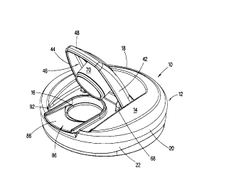
A lid (10) is provided which simplifies the procedure
for accessing the contents of a container while also
to allowing the container to be reliably sealed. As best
appreciated with reference to Figures 1 and 2, the present
invention includes a cap (12) which includes an upper
surface (14) having an aperture (16) therethrough. The cap
(12) further includes a peripheral edge (18) that
encompasses the upper surface (14).
As seen in Figure 4, preferably, the upper surface (14)
is generally dome shaped and declines towards the peripheral
edge (18) of the lid (10). Preferably, the peripheral edge
is a radiused portion (20) that interconnects the upper
2o surface (14) to a peripheral collar (22). Furthermore, as
seen in Figure 5, the peripheral collar (22) has an inner
surface (24) which includes a threaded portion (26). As is
well know by those skilled in the art, the cap (12) can be
received by a container, not shown, that has a corresponding
threaded portion. In accordance with the unique aspects of
this invention, the cap (12) may be secured to the container
through a variety of attachment mechanisms other than
through threaded portions without detracting from the novel
aspects of this invention.
CA 02255790 1998-12-14
-10-
The cap (12) also has a lower surface (28) and a ring
portion (30) disposed thereon. The ring portion (30) and
inner surface (32) of the peripheral collar (22) traps the
side walls of the container therebetween. When the cap (12)
of this invention is attached to a container, the engagement
of the inner surface (32) of the peripheral collar (22) and
the ring portion (30) acts to provide a liquid tight joint
between the lid (10) and the container.
The lid (10) also includes a cover (34) for sealing the
io aperture (16). In particular, the cap (12) includes an
elongate body (36) having a front wall portion (38) and an
oppositely disposed rear wall portion (40) along a
longitudinal axis of the elongate body (36). The elongate
body (36) further includes a pair of oppositely disposed
i5 side wall portions (42, 44) such that the cover (34)
provides a chamber (46) bounded by the elongate body (36)
and the front wall portion (38), rear wall portion (40) and
the side walls (42, 44).
In a preferred embodiment, the elongate body (36) of
2o the cover (34) is enclosed by the front wall portion (38),
the rear wall portion (40) and the side wall portions (42,
44) with a radiused portion (48) therebetween. Further, the
elongate body (36) includes a forward portion (50) and a
rearward portion (52). The rearward portion (52) generally
25 slopes towards the median portion (54) of the cover (34).
Disposed on the rearward portion (52) is a plurality of
gripping ribs (56) such that the user can easily actuate the
rearward portion (52) of the cover (34). In contrast, the
CA 02255790 1998-12-14
-11-
forward portion (50) of the elongate body (36) is generally
dome-shaped.
One novel aspect of this invention is a rocker
mechanism which allows the cover (34) to be rotated between
an open position, as shown in-Figure 2, and a closed
position, as shown in Figure 1. In a preferred embodiment,
the rocker mechanism is a pivot member (58) coupled to a lug
member (60). Most preferably, as best appreciated with
reference to Figure 2 and Figure 5, the pivot member (58) is
to a pair of pivot posts (62, 64) disposed on an inner surface
of the side wall portions (40, 42). The cap (12) includes a
pair of lug members (66, 68) that correspond to the pair of
pivot posts (62, 64) such that the pivot post (62) is
received in the lug (66) and the pivot post (64) is received
in the lug (68). As such, the cover (34) is securely
fastened to the cap (12).
With reference to Figure 7, the elongate body (36)
includes a plug (70). The plug (70) is sized to be
receivable within the aperture (16) so that when the cover
(34) is in the closed position the plug (70) is disposed
within the aperture (16). To ensure that the plug (70)
adequately seals the aperture (16), the plug includes an
annular groove (72) and a corresponding annular bead (74) on
the aperture (16). Accordingly, when the cover (34) is in a
closed position, the annular groove (72) is engaged in said
annular bead (74) such that the aperture (16) is sealed.
Furthermore, inadvertent opening of the container is guarded
against due the frictional engagement of the annular bead
(74) to the annular groove (72) when in the closed position.
CA 02255790 1998-12-14
-12-
In order to provide the cover (34) with an increased
degree of rotation, the cap (12) includes an arcuate
recessed portion (76) and an abutment portion (78).
Accordingly, the cap (12) is free to rotate until the rear
wall portion (40) abuts the abutment wall (78) thereby
preventing over rotation and damage to the cover (34). The
rear wall portion (40) includes a first knuckle (80) and the
arcuate recessed portion (76) includes a corresponding
second knuckle (82) which defines a pit (84). As can be
1o best appreciated with reference to Figure 5 and Figure 6,
the arcuate recessed portion (76) has a globally arcuate
shape allowing the unobstructed rotation of the rearward
portion (52) as the cover (34) is pivoted about the pivot
posts (62, 64). The cover (34) is secured in the open
position once the rear wall portion (40) is rotated adjacent
the abutment portion (78). The cover (34) is secured in the
open position by frictional engagement between the first
knuckle (80) and the second knuckle (82). Once in the open
position, the plug (70) is removed from contact with the
2o aperture (16) and retained in the open position thereby
preventing undesirable closure of the cover (34).
As best appreciated with reference to Figure 2 and
Figure 6, the cap (12) of this invention includes a pour
spout (86)on the upper surface (14) of the cap (12). More
specifically, the pour spout (86) of this invention includes
a concave channel portion (88) extending from the aperture
(16) and terminating at a lip (90). As seen in Figure 2,
the lip (90) extends beyond the peripheral collar (22) of
the cap (12). Further, the plug includes a U-shaped flange
CA 02255790 1998-12-14
-13-
(92) extending normal to the upper surface (14) thereby
isolating the concave channel (88) from the remainder of the
eap (12). The pour spout (86) has a peripheral shape which
corresponds to the shape of the forward portion (50) of the
elongate body (36). Further, the front wall (38), and the
side walls (42, 44) extend around the pour spout (86) to
close-off the pour spout from the surrounding environment.
Therefore, in addition to the container being sealed by the
plug (70), the pour spout (86) is also sealed off from
interaction with the environment.
In a preferred embodiment, the peripheral collar (22)
generally tapers inward and includes a plurality of inward
steps. As shown in Figure 7, the peripheral collar (22) is
shown as having a first inward step (94) and a second inward
step (96). Along with the tapering of the peripheral collar
(22), the inward steps (94, 96) reduce the cross-section of
the collar thereby reducing material usage and provide a
smooth transition between the side walls of the container,
not shown, and the lid of this invention. In an alternate
2o embodiment, the peripheral collar may have a knurled surface
or other equivalent member well known in the art to allow
the user to easily grasp the cap (12).
In accordance with this invention, the lid of this
invention may be manufactured from polypropylene plastic.
However, other various materials may be substituted while
still embodying this invention's novel aspects. Further,
the lid may be assembled from two components namely the cap
(12) and the cover (34) with a11 of the other components
herein described being integrally formed. However, it will
CA 02255790 1998-12-14
-14-
be appreciated that the above invention could be assembled
from separate components that are affixed together without
departing from the novel aspects of this invention.
In use, the operator of this invention can introduce a
fluid into a container either before or after attaching the
lid (10) of this invention to the container. The lid (10)
is then attached to the container via screwing the lid (10)
into secure attachment with the container. Alternatively,
this invention contemplates that various other attachment
1o mechanisms between the lid and the container may be
employed. Once attached, the lid (10) provides a fluid-
tight seal between the container and the lid (10).
The operator may utilize the invention by an
uncomplicated operation of the cover (34). When the user
i5 desires the cap (12) to be in the closed position, the user
simply will depress the forward portion (50) thereby
pivoting the cover (34) forward until the annular groove
(72) on the plug (70) is engaged by the annular bead (74) on
the aperture (16). In the closed position, the plug (70)
2o seals the fluid contained within the container. In
addition, the front wall portion (38) and the side wall
portions (42, 44) encompass and isolate the pour spout (86).
In this way, the fluid itself and the surface which the
fluid will contact when poured from the container, the pour
25 spout (86) is isolated from environmental contaminants.
When the user desires to the cover (34) to assume the
open position such that the fluid retained within the
container is accessible, the operator merely needs to
depress the rearward portion (52) of the cover (34) such
CA 02255790 1998-12-14
-15-
that the elongate body (36) rotates about the pivot posts
(62, 64). Successful depression is enhanced by the
incorporation of the plurality of gripping ribs (56). The
elongate member is retained in the open position by
s frictional engagement between the first knuckle (80) on the
rearward portion (52) and the second knuckle (82) on the
arcuate recessed portion (76). At this point, the operator
may safely pour fluid from the container without the cover
(34) interfering with the fluid as it flows from the lid
(10) .
From the above one can appreciate that the disclosed
invention has several advantages. One such advantage is
that the lid (10) of this invention allows fluid to be
securely retained within the container once the cover is
rotated into the closed position. As such, the fluid is
sealed from harmful contaminants or from undesirable
spillage. In addition, the pour spout (86) is also isolated
from the external environment due to the unique design of
the cover (34) which isolates the pour spout (86) from the
2o environment as well as the fluid itself. Alternatively, when
the operator desires to pour the liquid from the container,
the pour spout assures that the fluid is accurately directed
from the container.
Further, the lid may be operated in an uncomplicated
manner. Particularly, when utilized by juvenile, elderly,
or disabled users the lid of this invention allows for
simple actuation. The user simply depresses the rearward
portion (52) of the cover (34) to open the lid (10) and
depresses the forward portion (50) to close the lid (10).
CA 02255790 1998-12-14
-16-
In addition, the pivot posts (62, 64) are uniquely
located on an inward surface of the cover (34). Accordingly,
the stresses realized in the cover (34) are thereby reduced.
The unique design of the applicant's lid reduces the build-
s up of stress due to excessive cambering of the cover (34)
when actuated.
While our invention has been described in terms of
preferred embodiments, it is apparent that other forms could
be adopted by one skilled in the art, such as by
io incorporating the novel features of this invention within
lids which structurally differ from that shown in the
Figures. Accordingly, the scope of our invention is to be
limited only by the following claims.