Note: Descriptions are shown in the official language in which they were submitted.
CA 02255962 1998-11-20
~o cG -t p 5- D6. 7998
CVO 97/44967 PCTlEP9 7/02715
1
Title
A Dynamic Radio Backbone Transmission System.
Field of the invention
The present invention relates generally to telecom-
munication systems comprising a radio 1 ink connection betvreen two or more
tel ecommuni cati on uni is . P~tore speci fi cal 1 y, the i nvent i on provi
des a radi o
backbone transmission system for connecting a plurality of geographically
spread remote radi o access uni is to a network access uni t of a mobi 1 a
radi o
telecommunication net~~rork, such as a cellular mobile telecommunication
net4~rork, the radio access units each providing service to a particular
area or cell of the mobile radio telecommunication network.
Backctround of the invention
A typical cellular mobile communication system comprises
mobile radio subscriber units such as mobile telephones, a plurality of
radio base stations, each providing service to a geographical area or cell,
and hlobi 1 a servi ces Ss~ri tchi ng Centers (MSC) or P~lobi 1 a Tel ephone
Swi tchi ng
Offices (P~tTSO) to S~rhich the base stations connect. The 1~1SC and f~ITSO
are,
in turn, coupled to a conventional Public Switch Telephone Nettnork (PST~1)
and Integrated Servi ces Digi tal ~letwork ( ISDN) , for exampl e, for compl
eti ng
transmissions, such as telephone calls, between mobile radio subscribers
and landline subscribers.
Present cellular systems provide coverage over
relatively wide areas, i.e. relatively large cells. Analogue cellular
systems, such as designated A1~1PS, ETAC.S, NP~1T-450 and NhiT-900 have been
deployed throughout the world. Digital cellular systems are designated
IS-54B in North America and the pan-European GSt~t system (including DCS
1800 and PCS 1900) . These systems, and others, are descri bed, for exampl e,
in the book titled "Cellular Radio Systems", by Balston et al., published
by Artech House, Norwood, hlA., 1993.
First generation cellular mobile net~~rqrks provide
service to macrocells, having a range of 1 to 5 km front the base station
to the cell boundary, and large cells (5 to 35 km), ~~rith some satellite
cells ( > 500 km).
AMENDED SHEET
CA 02255962 1998-11-20
11'O 97/~49G7 PCTlEP97/01715
2
An important probl em i n vri rel ess cel 1 ul or communi cati on
is to provide full coverage cost effectively. This has lead to the
splitting of cells in dense traffic areas, adding microcells (10 to ~r00
m for pedestrians and 300 m to 2 km for vehicles) and minicells (500 m
to 3 km) overt aid by a macrocell structure. The overt aging macrocel l s
serve
lour-traffic areas and address cell crossings by mobile subscribers.
European patent application 0,690,643 discloses a radio
communication system, wherein a large cell of a central base station is
surrounded, at its outer periphery, by a plurality of macrocells, serviced
by decentralised radio basestations. Thedecentralised radio basestations
each connect to the central base station by a point-to-point link radio
backbone transmission system. The large cell and its surrounding macrocells
provide an extended service area. A plurality of adjacent service areas
make up the actual coverage area of the radio communication system.
As cellular penetration continues as forecasted, future
cel l ul or mobi 1 a netvrorks wi t l al so have pi cocel l s ( a fe;~r meters
) and
nanocells (up to 10 m), often in clusters of street microcells, :~rith each
cluster overlaid by a macrocell. In a typical cell overlay configuration,
each microcell has its os~rn base station providing service to the
corresponding cell, t~rhereas the several base stations are vrired to a
concentrator or access uni t rrhi ch, i n turn, i s coupl ed to an I~iSC or
11TS0.
In particular in a picocell and nanocell environment these ~rtired links
or loops, providing a static, fixed backbone infrastructure involve
substant~-al net:~rorking and transmission costs, not contributing to the
object of providing cost effective cellular mobile coverage.
An essential requirement for pico-, nano- or microcell
cel 1 ul or mobi 1 a netvrork systems i s , however, enabl i ng i nstal l ati
ons vrhi ch
are economic as to capacity and po:~rer. That is to say, the various
components of the system have to be designed such that an optimum bet:~reen
-geographical coverage, range, communication capacity and installation costs
can be achieved, in order to provide competitive vrireless connections.
-- Summary of the Invention
4~tith regard to the optimization of capacity and po~~rer,
the backbone infrastructure forms a critical design part for providing
a viable pico-, nano- and microcell cellular mobile neti~rork.
i~.!~'~~..W ,.i J';L:-! -
CA 02255962 1998-11-20
W'O 97/4-~9G7 PCT/EP97i02775
EPO - DG 1
3 1 7. 07. 1998
Accordingly, it is an object of the present invention
to provide a backbone infrastructure optimally designed for the connection
of the several base stations of micro-, nano- and picocells and the
corresponding network system access unit of a cellularmobile communication
system.
The invention is characterized in that the radio
backbone transmission system comprises dynamic access node means having
radio transceiver means, antenna means and control means, operatively
connected for accessing a plurality of common radio communication channels,
the radio access units comprising backbone access units having radio
transceiver means, antenna means and control means, each of the backbone
access units being operatively connected for accessing the plurality of
common radio communication channels, wherein the control means of the
dynamic radio access node means and the backbone access units are arranged
for adaptively selecting a free communication channel of the plurality
of common radio communication channels, the dynamic access node means being
arranged for connection to the network access unit.
The invention is based on the insight that optimization
as to capacity and power can be achieved through a transmission backbone
system that dynamically allocates its transmission resources upon demand
by dynamic channel access (DCA).
6y using DCA as the channel access technique of the
radio backbone system according to the present invention, all the common
radio communication channels of the backbone system can be used by the
~_5 pico-, nano- and microcell base station sites connecting to a Dynamic
radio
Access Mode (DA~~I) means vrithout the basic need for a channel or frequency
planning= This, because the DCA algorithm automatically prevents the
seizure of already occupied communication channels of cell.
By using the dynamic radio backbone transmission system
of the present i nventi on i n a cel lul ar mobi l a neturork for provi di ng
4rireless connections bett~reen several small cell radio base stations and
a concentrator or 1~STS0, a very flexible, economic, and high traffic
handling system can be obtained.
In a further embodiment of the invention, the radio
transceiver means, antenna means and control means of the dynamic radio
access node means are arranged for accessing the plurality of common radio
communication channels in directionally separated transmission sectors,
AMENDED SHEET
CA 02255962 1998-11-20
WO 97l-14967 PCTIEP97i0271~
4
S~rherein the control means are arranged to co-operate vrith the backbone
access units in a transmission sector for adaptively selecting a free radio
communication channel of said plurality of common radio communication
channels, ~~rhich radio communication channel, vrhen accessed, can be reused
by the same dynamic radio access node means but is individual to a radio
link connection in a transmission sector.
By sectorizing, the effective range of a radio link
connection can be extended. That is to say, by radiating the RF power of
a transmitter means into a directionally limited geographical are, the
effective range of the radio. transmitter can be extended compared to
omnidirectional coverage. By reciprocity, the same holds for the reception
sensitivity of the receiver means.
Further, the common radio communication channels can
be reused from sector to sector within the same DAP1, ~~rhich provides a very
efficient use of transmission resources, such as required.
In a practical embodiment of the invention, the dynamic
radio access mode means comprise a number of radio access modules, each
having radio transceiver means and control means arranged for accessing
a plurality of common radio communication channels. The access modules
0 are operatively connected for accessing the common radio communication
channels in an associated transmission sector. The various radio access
modules may operate independently from each other, without any need for
control equipment as to the occupation of common radio communication
channel s =
The radio node means of the invention can be
advantageously assembled of independently operating access modules designed
for operation under existing business cordless technologies, such as CT2
or DECT, both of which use DCA as their channel access technique. It grill
be understood that the .radio node means are not limited to the use of this
type of radio access modules. Other technologies and derivatives of these
technologies providing communication channels under the control of a DCA
algorithm may be also used.
By a suitable positioning of the different radio access
modules, omnidirectional coverage of an area or (overlay) cell can be
achieved, such that in each (,overlay) cell and all its adjacent cells,
all the common radio communication channels of the system are potentially
available for establishing a radio link connection.
."S,iv'~'e~c!: ,i~c~ T
CA 02255962 1998-11-20
~~'O 97/t4967 PCTrEP97JO27I5
As mentioned above, the DCA algorithm occupies only
free channels in a given geographical area. A required amount of
redundancy, both for repair and maintenance purposes and to account for
an increase in the communication capacity for a given sector, can be easily
5 achieved by providing the common radio communication channels in a given
sector by at least tyro radio access modules of the unit, vrhich radio access
modules may operate simultaneously during normal operation.
In order to prevent interferences t~rhile communication
bett~reen the node access means and a backbone access unit is established
and in progress, the control means according to the invention operates
preferably using an improved DCA technique, called Continuous Dynamic
Channel Selection (CDCS). The basic property of CDCS is that a radio
communi cati on channel i s accessed whi ch i s 1 east i nterfered at the
moment
of its selection.
The radio access modules and backbone access units
preferably comprise transceiver means, arranged to provide a plurality
of co:~~munication channels based on a multiple access technique, such as
Time Division 1~1u1tiple Access (TDtiA), Frequency Division Multiple Access
(FDt~tA) and Code Division ~~iultiple Access (COMA), for example.
A more elaborated discussion on DCA and CDCS at the
interface of a remote mobile subscriber unit and a fixed radio network
access unit can be found in US Patents 4,628,152; 4,731,812 and a paper
by D. Akerberg, "Novel Radio Access Principles Useful for the Third
Generatio''n Mobile Radio Systems", The Third IEEE International Symposium
on Personal, Indoor and hlobile Radio Communication, Boston, Massachusetts,
October 19-21, 1992.
In a further embodiment of the dynamic radio backbone
transmission system according to the invention, a_plurality of dynamic
radio access node means are connected to radio node control means. The
radio node control means are arranged for connection to a netvrork access
unit,~such as a mobile service switching center, a mobile telephone
switching office or base station equipment of the mobile radio telecommuni-
cati on netarork.
A very efficient use of transmission resources is
obtained, in a yet further embodiment of the present invention >-rherei~
the radio node control means and the dynamic radio access node means are
operatively connectedfor adaptively accessing afree communication channel
AMENDED SHEET
CA 02255962 2005-09-30
6
of a plurality of com;aon communication channels accc~sible at the
connection between the radio node control means and the dynamic radio
access node means.
In this embodiment, both the communic=Lion channels
at the interface bets~reen the radio node control means and the dynamic rzdio
access node means as well as the radio communication charm=is at the air
interface bett~reen the dynamic radio access node means and the backbone
access units are adaptively accessible, depending on the load of the radio
access unit or radio base stations of the several pico-, nano- or micro
cells.
In order to connect over even larger distances, in a
yet further embodiment of the dynamic radio backbone trans~-,issi~on system
according to the present invention, the transceiver means o. the dynamic
radio node access means are connected to a range enhancer unit.
This range enhancer unit comprises frequency conversion
means, RF ampi iffier means and antenna means. The frequency conversion means
comprise a receive and transmission part, each part including mixer means
connecting to local oscillator snitch means. These switch means are
controlled by a local oscillator for alternately converting transmit and
receive signals to one and another frequency, following a Time Division
Duplex (TDD) communication protocol.
According to an aspect of the invention there
is provided a radio backbone transmission system for
connecting a plurality of geographically spread remote
radio access units to a network access unit of a mobile
radio telecommunication network, such as a cellular mobile
telecommunication network, the radio access units each
providing service to a particular area or cell of the
mobile radio telecommunication network, wherein the radio
backbone transmission system comprises dynamic access node
means having radio transceiver means, antenna means and
contro l means, operatively connected for accessing a
plurality of common radio communication channels, the radio
access units comprising backbone access units having radio
CA 02255962 2005-09-30
6a
transceiver means, antenna means and control means, each
of the backbone access units being operatively connected
for accessing the plurality of common radio communication
channels, wherein the control means of the dynamic radio
access node means and the backbone access units are
arranged for adaptively selecting a free communication
channel of the plurality of common radio communication
channels, the dynamic access node means being arranged for
connection to the network access unit.
Brief Description of the Drawings
Fig. ~ ShO~~rS, in a very schematic ro~ner; part of
cellular telecommunication network having a dynamic radio backbone
transmission system according to the present invention, in~;;hich several
smaller cells are clustered in transmission sectors.
Fig. 2 shos~rs, in a very schematic mann_r, a backbone
system architecture according to the present invention .or use in the
network of Fig. 1.
CA 02255962 1998-11-20
WO 97/44967 PCT/EP97/02715
7
Fig. 3 shows a block diagram of a radio module for use
in the radio backbone system according to the present invention.
Fig. 4 shows, in a very schematic manner, a backbone
system architecture having a range enhancer unit according to the present
invention.
Fig. 5 shows a circuit diagram of a range enhancer unit
shown in Fig. 4.
Detailed Description of the Embodiments
Without the intention of a limitation, the invention
will now be described and illustrated with reference to an exemplary
embodiments in a cellular mobile telecommunication network.
in order to increase the traffic handling capacity of
a cellular mobile network within a given area, it is necessary. Fig. 1
shows a typical embodiment of a dynamic radio backbone transmission system
in a cellular mobile network, in which a number of relatively small cells
4, such as pi cocel l s, nanocel l s and mi croce71 s are c1 usted i n transmi
ssi on
sectors 3. These transmission sectors may be contained in or overlaid by
a relatively large cell, such as a macroce7l. For simplicity the various
cells and transmission sectors are depicted in circular form.
Each cell 4 comprises a radio access unit providing
servi ce to mobi 1 a uni is i n the parti cul ar cel l 4. The vari ous radi o
access
units connect by a radio link 5 to so-called Dynamic radio Access Node
means (DAN) 1. The DAN 1 connects to a network access unit, such as a
Mabi 1 a Tel ephone Swi tchi ng Offi ce (MTSO) , a Mobi 1 a servi ce Swi tchi
ng Centre
(MSC) or radio base station equipment such as a Base Station Controller
(BSC) of a cellualr base station providing service to a sector or macroce7l
3, for example. In the figure, it is assumed that the DAN 1 connects
directly to an MTSO 2.
In particular in dense residential or metropolitan
areas , a 1 arge number of smal 1 cel 1 s 4 may be i nvol ved . A typi cal cel
l u1 ar
network may comprise hundreds of radio access units, thousands of mobile
stations and more than one MTSO 2.
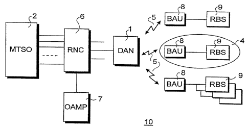
Fig. 2 shows a block diagram of a backbone transmission
system architecture 10 for use in a network as shown in Fig. 1. The DAN
CA 02255962 1998-11-20
WO 97/44967 PCT/EP97/02715
8
1 connects to the MTSO 2 via a so-called Radio Node Controller (RNC) 6.
The RNC 6 controls one or more DAN's 1 and is the interface of the radio
backbone system towards both the MTSO Z and an Operation Administration
Maintenance and Provisioning {DAMP) unit 7.
A cell 4 comprises a so-called Backbone Access Unit r
(BAU) 8 which connects to a radio access unit or Radio Base Station (RBS)
9 of a cell 4. In a GSM micro/pico- cellular network, for example, the
RBS 9 is a physically small unit comprising radio transceiver and control
equipment with integrated antennas typically located 5-IO m above street
level.
As already mentioned in the introductory part to the
present invention, the radio access node means and radio backbone units
according to the invention can be based on radio access modules operating
in accordance with one of the present business cordless technologies, such
i5 as designated CT2, CT3 and DECT, all using DCA for accessing one of a
plurality of common radio channels.
Fig. 3 shows a block diagram of a radio access module
20, which operates in accordance with the relative protocois of the DECT
standard. In short, the DECT protocol includes a Multi Carrier/Time
Division Multiple Access/Time Division Duplex (MC/TDMA/TDD) digital radio
access technique, providing ten radio carriers, each divided into 24 time-
slots which serve 12 duplex communication channels, called a frame.
The access module 20 has a wired output connection 21.
Central Control and Application Logic 22 detects incoming calls and
controls outgoing calls, and selects suitable combinations of carrier and
time slots in accordance with the DCA/CDCS algorithm, and merges via a
multiplexer 23 the different connections and time slots. The module 20
has a frame and slot synchronization unit 24 which controls slot reception
and transmission timing. The central control logic 22 also controls a
Transmit/Receive (T/R) switch 25 and an antenna diversity switch 26 which
connects to antenna outputs 31, respectively, if antenna diversity is
implemented. With antenna diversity, if a radio connection provides no '
good communi cati on, the control 1 ogi c fi rst tri es the other antenna
before
changing the radio communication channel.
The radio interface of the module 20 consists of a
receiver/demodulator 27 and a transmitter/modulator 28. Synchronisation
CA 02255962 1998-11-20
WO 97/44967 PCT/EP97/02715
9
and control information is stripped from received data by unit 29, whereas
such information is added to the data to be transmitted by unit 30,
connected as shown.
In accordance with the present invention, each of the
120 radio channels of a unit 20 is used in a DAN 1 are accessible
by a BAU 8 of the dynamic backbone transmission system shown in Fig. 2.
In accordance with the DCA/CDCS technique, radio communication channels
at the air interface 5 are selected and ascessed from any of these 120
channels for communication purposes, provided such channel is not used
by another radio link connection in a sector 3 or cell 4, whether or not
processed via the same radio access module 20. After selection, such
channel is individual to the established radio link connection.
As shown, the DAN 1 is positioned at the point of
intersection of the sectors 3, such that the radio access units (not shown)
of each small cell 4 connect via the radio interface 5 of the DAN 1 to
the MTSO 2.
The communication channels available at the interface
between the RNC 6 and the DAN's 1 are, in a further embodiment of the
invention, adaptively selectible for connecting radio base stations 9 to
the MTSO 2. It will be appreciated by those skilled in the art that by
providing both the communication channels at the interface between the
RNC 6 and a DAN 1 as well as at the radio interface between a DAN 1 and
a BAU 8, a very efficient dynamic radio backbone transmission system is
provided.
It will be understood that this is a very efficient
manner of connecting the various small cells without the basic need for
a channel or frequency planning.
This type of dynamic point to multi-point backbone radio
transmission solution is very cost-efficient and attractive both when the
traffic generated by the several small cells 4 is relatively low and
(temporarily) not justifying a wired link and in case of relatively high
~ transmission requirements (e.g. 2 * 64 kb/s per radio base station 9)
making it easy to introduce network redundancy when required. Further,
the DAN 1 may act as a consolidation point from which it will be easy to
go from one media to the other.
CA 02255962 1998-11-20
BYO 97/-t~S967 PCT/EP97/027I5
0
In a particular embodiment, at the MTSO/RNC-interface
a number of 64 kb/s communication channels are (permanently) assigned to
an RBS 9. At the DAN/BAU-radio interface 5 the available radio communica-
tion channels are dynamically allocated to each RBS, depending on its load.
5 On the BAU/RBS-interface a limited number of 2-6 64 kb/s communication
channels are available for an RBS; i.e. 4-12 32 kb/s channels between a
BAU 8 and OAN I in case of a DECT radio air interface. Additional to the
communication channels, a semi-permanent signalling channel may be provided
over the backbone transmission system, i.e. t~tTSO 2/RNC o/DAN 1.
10 In areas of very lour subscriber density from a cost
point of vietd there is a need for interconnecting more 1~ridely spread
clusters of remote units 8, 9. Among others for use in such rural areas,
there is provided a so-called Range Enhancer Unit (REU) 14 as shot~rn in
Fig. 4. The REU 14 is positioned at the site of the DAN.
In its simplest embodiment the REU 14 transponds the
radio signal at the radio communication link 5 - vrhich may be a radio
signal according to the DECT standard operating in the 1900 t~1Hz band, for
example - to an arbitrary frequency band, typically at 450 or 800 t~iHz.
The transmit signal is also amplified to a level sufficient to provide
a range larger than the range of a radio access module 20 or DAtd 1. A
typical range of an REU 14 t~rould be 12-15 km.
The REU 14 at the site of a DAN 1 may have as many
converter, amplifier and antenna combinations as there are radio access
modules 20 in a DAt~ 1. In a practical embodiment, the radio signal at the
antenna output 31 of a particular radio access module 20 is fed to the
REU 14 and converted. At a cell site 4, another REU 15 is installed in
order to reconvert the radio signal 16 from the REU 14 to the frequency
band of the radio communication link 5 vrhich may be a radio signal at the
DECT frequency band, for example.
The reconverted .output signal of the REU 15 may be fed
to a so-called Radio Repeater Station (RRS) 17 for providing radio coverage
and service to a subscriber cell 4 following the protocol and frequency
of the radio communication link 5. Such an RRS 17 may have a wired or a
s~rirel ess 1 ink with the REU 15. The RRS I7 i s essenti al 1y constructed 1
i ke
a radio access module 20 (see Fig. 3). The main difference is that there
is a further transmit/receive output/input (or two vrhen diversity is
AMENDED SHEET
CA 02255962 1998-11-20
'V0 97/-~~967 PCT/EP9'7r027Ij
11
applied) controlled by the Central Control and Application Logic 22 s~rhich
also connects the information of transmit/receive time slots at the antenna
31 to appropriate transmit/receive time slots at the transmit/receive
output/input. To this end the data of at the multiplexer 23 is fed into
shift registers (not shos~rn) vrhich, under the control of the Central Control
and Application Logic 22, are controlled to timely shift the data back
into the mul ti p1 exer 2I foi l ovri ng the appl i ed repeater protocol . Th
i s
further output/input may be coupled to the receiver/demodulator 27 and
the transmitter/modulator 28 or may be provided as a t~rired output/input.
Reference is made to International Patent Application t~10 94/19877,
t~lith the REU concept according to the present invention
i t i s pons i b1 a to re-create subscri ber cel 1 s 4 anyvrhere sni th i n
the coverage
area of an REU 14, I5 combination. In the case of isolated subscribers
(at farms or the like) an REU 15 can be directly coupled to a subscriber
remote unit or Fixed Access Unit (FAU) 19, as shot~rn. In the case of a so-
called multi-line FAU 19, i.e. a FAU 19 having multiple output subscriber
terminals, an REU 15 and FAU 19 can be shared by a number of (neighbouring)
subscribers, for example.
In the present invention, a DAN 1 may be co-located
sari th one or a p1 oral i ty of REU 14 S~rhi ch reduces the overal 1 sys tem
installation costs significantly.
Further, through a splitter device (not shot~rn), the
antenna output of a radio access module 20 may connect both directly to
an antenna and to an REU 14. Due to its amplification, the signal for
feeding-to the REU 14 can be relatively wreak thus not noticeably affecting
the power to and from an antenna.
If diversity is applied, i.e. tt~ro antenna outputs 31
at a radio access module 20 (Fig. 3), an REU 14 may be connected to each
of the antenna outputs such that for each diversity path a separate REU
trill be active. At the subscriber site only one REU 15 may be used, t~rhich
is able to receive the radio signals of both REU 14. By inserting the REU
14 in the midpoint path of the antenna diversity s~~titch 26 (Fig. 3) one
REU is sufficient in case of diversity. Hos.rever, this may require an
additional modification of an existing radio access module 20.
A.;~r~,"~L~;_.=i ,;:..:
CA 02255962 1998-11-20
1
«'O 97/-t.t967 PCT/EP97/02715
12
With the REU concept according to the invention,
although several radio access modules 20 are mounted at the same site,
for there operation they are to be regarded as providing service to
different geographically spread cells having no overlapping coverage such
that each radio access modules can provide its full capacity to the area
to t,rhi ch i t i s addressed.
Fig. 5 shows, in a very schematic manner, a circuit
diagram of an REU for TDD operation. A low noise receiver RX 35 connects
Snith its input to a Transmit/Receive (T/R) Swltch 37 and connects with
its output to an input of a mixer 39. A transmitter TX 36 connects with
its output to the T/R switch 37 and connects with its input to an output
of a mixer 40. Both mixers 39, 40 connect with an input to an output of
a so-called Local Oscillator (LO) ss~ritch 38, the input of t~thich connects
to a Local Oscillator (LO) 41. Another output of mixer 39 and another input
of mixer 40 connect to an input respectively an output of a coupler 42.
The coupler 42 provides a combined transmit/receive input 43 of the REU
vrhile the T/R switch 37 provides a transmit/receive output 44 of the REU.
Due to the TDD operation, no filtering is required to
separate the transmit and receive paths. The switching between transmit
and receive mode is provided by the ss~ritching of the local oscillator to
any of the mixers 39, 40 and the T/R switch 37. An appropriate control
signal can be provided by the radio access modules 20 or via a separate
signalling path 45 and signalling means (not shown), for example.
A1 though the present i nventi on h as been descri bed wi th
i
reference to a specific embodiment and design of an access unit and in
more detai 1 vri th respect to i is use i n a GShi communi cati on system, i t
wi 11
be understood that the novel idea of the present invention can be used
~~rith several access technologies and many different embodiments of the
dynamic access node means and backbone access units.
AMENDED SHEET