Note: Descriptions are shown in the official language in which they were submitted.
CA 022~6469 1998-11-23
W O97/45847 PCT/SE97/00875
Tr~ ns former re~ctor
TECHNICAL FIELD
..
The present invention relates to a power transformer/reactor.
For all transmission and distribution of electric energy,
transformers are used and their task is to allow exchange of
electric energy between two or more electric systems. A
transformer is a classical electrical product which has
existed, both theoretically and practically, for more than
100 years. This is manifestly clear from the German patent
specification DE 40414 from 1885. Transformers are available
in all power ranges from the VA up to the lO00 MVA range.
With respect to the voltage range, there is a spectrum up to
the highest transmission voltages which are being used today.
A transformer belongs to an electrical product group which,
regarding the fundamental mode of operation, is relatively
easy to understand. For the energy transfer between the
electric systems, electromagnetic induction is utilized.
There are a great number of textbooks and articles which more
or less theoretically and practically describe the theory,
calculations, manufacture, use, service life, etc., of the
transformer. In addition, there are a large number of patent
documents relating to successively improved embodiments of
the different parts of a transformer, such as, for example,
windings, core, tank, accessories, cooling, etc.
The invention relates to a transformer belonging to the so-
called power transformers with a rated power ranging from a
few hundred kVA up to more than 1000 MVA with a rated voltage
ranging from 3-4 kV and up to very high transmission
voltages, 400 kV to 800 kV or higher.
The inventive concept which is the basis of the present
invention is also applicable to reactors. The following
CA 022~6469 1998-11-23
WO 97/45847 PCT/SE97/00875
description of the background art, however, mainly relates to
power transformers. As is well-known, reactors may be
designed as single-phase and three-phase reactors. As regards
insulation and cooling there are, in principle, the same
embodiments as for transformers. Thus, air-insulated and oil-
insulated, self-cooled, oil cooled, etc., reactors are avail-
able. Although reactors have one winding (per phase~ and may
be designed both with and without an iron core, the descrip-
tion of the background art is to a large extent relevant to
reactors.
BACKGROUND ART, THE PROBLEMS
In order to place a power transformer/reactor according to
the invention in its proper context and hence be able to
describe a new approach in accordance with the invention in
addition to the advantages afforded by the invention with
respect to the prior art, a relatively complete description
of a power transformer as it is currently designed will first
be given below as well in addition to the limitations and
problems which exist when i~ comes to calculations, design,
insulation, earthing, manufacture, use, testing, transport,
etc., of these transformers.
With respect to the above-mentioned, there is a comprehensive
literature describing transformers in general, and more
particularly, power transformers. Reference may be made, for
example, to the following:
The J ~ P Transformer Book, A Practical Technolo~y of the
Power Transformer, by A. C. Franklin and D. P. Franklin,
published by Butterworths, edition 11, 1990.
Regarding the internal electrical insulation of windings,
etc., the following can be mentioned:
CA 02256469 1998-11-23
WO 97145847 PCT/SE97/00875
Transformerboard Die Verwendun~ von Transformerboard in
Grossleistungstransformatoren by H. P. Moser, published by H.
Weidman AG, CH-8640 Rapperswil.
From a purely general point of view, the primary task of a
power transformer is to allow exchange of electric energy
between two or more electrical systems of, usually, different
voltages with the same frequency.
A conventional power transformer comprises a transformer
core, in the following referred to as a core, often of lami-
nated oriented sheet, usually of silicon steel. The core
comprises a number of core limbs, connected by yokes which
together form one or more core windows. Transformers with
such a core are often referred to as core transformers.
Around the core limbs there are a number of windings which
are normally referred to as primary, secondary and control
windings. As far as power transformers are concerned, these
windings are practically always concentrically arranged and
distributed along the length of the core limbs. The core
transformer usually has circular coils as well as a tapering
core limb section in order to fill up the window as
effectively as possible.
2~ In addition to the core type transformer there is so-called
shell-type transformer. These are often designed with
rectangular coils and a rectangular core limb section.
Conventional power transformers, in the lower end of the
above-mentioned power range, are sometimes designed with air
cooling to dissipate the heat from inherent losses. For
protection against contact, and for possibly reducing the
external magnetic field of the transformer, it is often
provided with an outer casing provided with ventilation
openings.
CA 022~6469 1998-11-23
W 097/45847 PCT/SE97/00875
Most of the conventional power transformers, however, are
oil-cooled. One of the reasons for this is that the oil has
an additional very important function as insulating medium.
An oil-cooled and oil-insulated power transformer is
therefore surrounded by an external tank on which, as will be
clear from the description below, very high demands are
placed.
Usually, means for water-cooling of the oil are provided.
The following part of the description will for the most part
refer to oil-filled power transformers.
The windings of the transformer are formed from one or
several coils connected in series built up of a number of
turns connected in series. In addition, the coils are
provided with a special device to allow switching between the
taps of the coils. Such a device may be designed for tapping
with the aid of screw joints or more often with the aid of a
special switch which is operable in the vicinity of the tank.
In the event that switching can take place for a transformer
under voltage, the changeover switch is referred to as an on-
load tap changer whereas otherwise it is referred to as a de-
energized tap changer.
Regarding oil-cooled and oil-insulated power transformers in
the upper power range, the contacts of the on-load tap
changers are placed in special oil-filled containers with
direct connection to the transformer tank. The contacts are
operated purely mechanically via a motor-driven rotating
shaft and are arranged so as to obtain a fast movement during
the switching when the contact is open and a slower movement
when the contact is to be closed. The on-load tap changers as
such, however, are placed in the actual transformer tank.
During the operation, arcing and sparking occur. This leads
to degradation of the oil in the containers. To obtain less
arcs and hence also less formation of soot and less wear on
CA 02256469 1998-11-23
W 097/4S847 PCT/SE97/00875
the contacts, the on-load tap changers are usually connected
to the high-voltage side of the transformer. This is due to
the fact that the currents which need to be broken and
connected, respectively, are smaller on the high-voltage side
than if the on-load tap changers were to be connected to the
low-voltage side. Failure statistics of conventional oil-
filled power transformers show that it is often the on-load
tap changers which give rise to faults.
In the lower power range of oil-cooled and oil-insulated
power transformers, both the on-load tap changers and their
contacts are placed inside the tank, This means that the
above-mentioned problems with respect to degradation of the
oil because of arcing during operation, etc., affect the
whole oil system.
From the point of view of applied or induced voltage, it can
broadly be said that a voltage which is stationary across a
winding is distributed equally onto each turn of the winding,
i.e., the turn voltage is equal on all the turns.
From the point of view of electric potential, however, the
situation is completely different. One end of a winding is
usually connected to earth. This means, however, that the
electric potential of each turn increases linearly from
practically zero in the turn which is nearest the earth
potential up to a potential in the turns which are at the
other end of the winding which correspond to the applied
voltage.
This potential distribution determines the composition of the
insulation system since it is necessary to have sufficient
insulation both between adjacent turns of the winding and
between each turn and earth.
The turns in an individual coil are normally brought together
into a geometrical coherent unit, physically delimited from
the other coils. The distance between the coils is also
CA 022~6469 1998-11-23
W O 97/45847 PCT/SE97/00875
determined by the dielectric stress which may be allowed to
occur between the coils. This thus means that a certain given
insulation distance is also required between the coils.
According to the above, sufficient insulation distances are
also required to the other electrically conducting objects
which are within the electric field from the electric
potential locally occurring in the coils.
It is thus clear from the above-mentioned description that
for the individual coils, the voltage difference internally
between physically adjacent conductor elements is relatively
low whereas the voltage difference externally in relation to
other metal objects - the other coils being included - may be
relatively high. The voltage difference is determined by the
voltage induced by magnetic induction as well as by the
capacitively distributed voltages which may arise from a
connected external electrical system on the external connec-
tions of the transformer. The voltage types which may enter
externally comprise, in addition to operating voltage,
lightning overvoltages and switching overvoltages.
In the current conductors of the coils, additional losses
arise as a result of the magnetic leakage field around the
conductor. To keep these losses as low as possible,
especially for power transformers in the upper power range,
the conductors are normally divided into a number of
conductor elements, often referred to as strands, which are
connected in parallel during operation. These strands must be
transposed according to such a pattern that the induced
voltage in each strand becomes as equal as possible and so
that the difference in induced voltage between each pair of
strands becomes as small as possible for internally
circulating current components to be kept down at a
reasonable level from the loss point of view.
When designing transformers according to the prior art, the
general aim is to have as large a quantity of conductor
CA 022~6469 1998-11-23
W 097/45847 PCTISE97/00875
material as possible within a given area limited by the so-
called transformer window, generally described as having as
high a fill factor as possible. The available space shall
comprise, in addition to the conductor material, also the
5 insulating material associated with the coils, partly
r internally between the coils and partly to other metallic
components including the magnetic core.
The insulation system, partly within a coil/winding and
10 partly between coils/windings and other metal parts, is
normally designed as a solid cellulose- or varnish-based
insulation nearest the individual conductor element, and
outside of this as solid cellulose and liquid, possibly also
gaseous, insulation. In this way, windings with insulation
15 and possible support parts represent large volumes which will
be subjected to high electric field strengths which arise in
and around the active electromagnetic parts of the
transformer. In order to predetermine the dielectric stresses
which arise and achieve a ~imensioning with a mi~iml]m risk of
20 breakdown, good knowledge of the properties of insulating
materials is required. It is also important to achieve such a
surrounding environment that it does not change or reduce the
insulating properties.
25 The currently predo~in~nt insulation system for high-voltage
power transformers comprises cellulose material as the solid
insulation and transformer oil as the liquid insulation. The
transformer oil is based on so-called mineral oil.
30 The transformer oil has a dual function since, in addition to
the insulating function, it actively contributes to cooling
of the core, the winding, etc., by removal of the loss heat
o~ the transformer. Oil cooling requires an oil pump, an
external cooling element, an expansion vessel, etc.
The electrical connection between the external connections of
the transformer and the immediately connected coils/windings
-
CA 022~6469 1998-11-23
W 097/45847 PCT/SE97/00875
is referred to as a bushing aiming at a conductive connection
through the wall of the tank which, in the case of oil-filled
power transformers, surrounds the actual transformer. The
bushing is often a separate component fixed to the tank wall
and is designed to withstand the insulation requirements
being made, both on the outside and the inside of the tank,
while at the same time it should withstand the current loads
occurring and the resulting current forces.
It should be pointed out that the same requirements for the
insulation system as described above regarding the windings
also apply to the necessary internal connections between the
coils, between bushings and coils, different types of
switches and the bushings as such.
All the metallic components inside a power transformer are
normally connected to a given earth potential with the
exception of the current-carrying conductors. In this way,
the risk of an unwanted, and difficult-to-control, potential
increase as a result of capacitive voltage distribution
between current leads at high potential and earth is avoided.
Such an unwanted potential increase may give rise to partial
discharges, so-called corona, which may be revealed during
the normal acceptance tests, which partially are performed,
compared with rated data, increased voltage and frequency.
Corona may give rise to damage during operation.
The individual coils in a transformer must have such a mecha-
nical ~;m~nsioning that they may withstand any stresses
occurring as a consequence of currents arlsing and the resul-
ting current forces during a short-circuit process. Normally,
the coils are designed in such a way that the forces arising
are absorbed within each individual coil, which in turn may
mean that the coil cannot be ~imen~ioned optimally for its
normal function during normal operation.
CA 022~6469 1998-11-23
W 097/45847 PCT/SE97/00875
Within a narrow voltage and power range of oil-filled power
transformers, the windings are designed as so-called helical
windings. This implies that the individual conductors
mentioned above are replaced by thin sheets. Helical-wound
power transformers are manufactured for vo~tages of up to 20-
30 kV and powers of up to 20-30 MW.
The insulation system of power transformers within the upper
power range requires, in addition to a relatively complicated
design, also special manufacturing measures to utilize the
properties of the insulation system in the best possible way.
In order to obtain a good insulation to be obtained, the
insulation system shall have a low moisture content, the
solid part of the insulation shall be well impregnated with
the surrounding oil and the risk of remaining "gas" pockets
in the solid part must be minimal. To ensure this, a special
drying and impregnating process is carried out on a complete
core with windings before it is lowered into a tank. After
this drying and impregnating process, the transformer is
lowered into the tank which is then sealed. Before filling of
oil, the tank with the immersed transformer must be emptied
of all its air. This is done in connection with a special
vacuum treatment. After carrying this out the tank is filled
with oil.
In order to obtain the promised service life, etc., almost
absolute vacuum is required during the vacuum treatment. This
thus presupposes that the tank which surrounds the trans-
former is designed for full vacuum, which entails a
considerable consumption of material and manufacturing time.
If electric discharges occur in an oil-filled power trans-
former, or if a local considerable increase of the tempera-
ture in any part of the transformer occurs, the oil
disintegrates and gaseous products dissolve in the oil. The
transformers are therefore usually provided with monitoring
devices for detection of gas dissolved in the oil.
, .. . . _
CA 022~6469 1998-11-23
W O 97/45847 PCT/SE97/00875
For weight reasons large power transformers are transported
without oil. On-site installation of the transformer at the
customer re~uires, in turn, renewed vacuum treatment. In
addition, this is a process which, furthermore, has to be
repeated each time the tank is opened for some repair work or
nspectlon .
It is obvious that these processes are very time-consuming
and cost-demanding and constitute a considerable part of the
total time for manufacture and repair while at the same time
requiring access to extensive resources.
The insulating material in conventional power transformers
constitutes a large part of the total volume of the transfor-
mer. For a power transformer in the upper power range, oil
quantities in the order of several tens of cubic metres of
transformer oil are not unusual. The oil which exhibits a
certain similarity to diesel oil is thinly fluid and exhibits
a relatively low flash point. It is thus obvious that oil
together with the cellulose constitutes a non-negligible fire
hazard in the case of unintentional heating, for example at
an internal flashover and a resulting oil spillage.
It is also obvious that, especially in oil-filled power
transformers, there is a very large transport problem. Such a
power transformer in the upper power range may have a total
oil volume of several decades of cubic metres and may have a
weight of up to several hundred tons. It is realized that the
external design of the transformer must sometimes be adapted
to the current transport profile, i.e., for any passage of
bridges, tunnels, etc.
A short summary of the prior art with respect to oil-filled
power transformers follows hereafter in which both its
limitations and problem areas will be described:
CA 022~6469 1998-11-23
PCT/SE97/00875
W 097/45847
11
An oil-filled conventional power transformer
- comprises an outer tank which is to house a transformer
comprising a transformer core with coils, oil for insulation
and cooling, mechanical support devices of various kinds,
etc. Very large mechanical demands are placed on the tank,
since, without oil but with a transformer, it shall be
capable of being vacuum-treated to practically full vacuum.
The tank requires very extensive manufacturing and testing
processes and the large external dimensions of the tank also
normally entail considerable transport problems;
- normally comprises a so-called pressure-oil cooling. This
cooling method requires the provision of an oil pump, an
external cooling element, an expansion vessel and an expan-
sion coupling, etc.;
- comprises an electrical connection between the e~ternal
connections of the transformer and the immediately connected
coils/windings in the form of a bushing fixed to the tank
wall. The bushing is designed to withstand any insulation
requirements made, both regarding the outside and the inside
of the tank;
- comprises coils/windings whose conductors are divided into
a number of conductor elements, strands, which have to be
transposed in such a way that the voltage induced in each
strand ~ecomes as equal as possible and such that the
difference in induced voltage between each pair of strands
becomes as small as possible;
- comprises an insulation system, partly within a
coil/winding and partly between coils/windings and other
metal parts which is designed as a solid cellulose- or
3~ varnish-based insulation nearest the individual conductor
element and, outside of this, solid cellulose and a li~uid,
possibly also gaseous, insulation. In addition, it is
... . ..
CA 022~6469 l998-ll-23
W 097/45847 PCT/SE97/00875
12
extremely important that the insulation system exhibits a
very low moisture content;
- comprises as an integrated part an on-load tap changer,
surrounded by oil and normally connected to ~he high-voltage
winding of the transformer for voltage control;
- comprises oil which may entail a non-negligible fire hazard
in connection with internal partial discharges, so-called
corona, sparking in on-load tap changers and other fault con-
ditions;
- comprises normally a monitoring device for monitoring gas
dissolved in the oil, which occurs in case of electrical dis-
charges therein or in case of local increases of the tempe-
rature;
- comprises oil which, in the event of damage or accident,
may result in oil spillage leading to extensive environmental
damage.
SU~ RY OF THE INVENTION, ADV2~NTAGES
The object of the invention is to offer a transformer concept
within the power range which has been described under the
description of the background art, that is, so-called power
transformers with a rated power ranging from a few hundred
kVA up to over 1000 MVA with a rated voltage ranging from 3-4
kV and up to very high transmission voltages, such as 400 kV
to 800 kV or higher, and which does not entail the disadvan-
tages, problems and limitations which are associated with the
prior art oil-filled power transformers according to what is
clear from the above-mentioned description of the prior art.
The invention is based on the realization that, by designing
.,
CA 022~6469 l998-ll-23
W 097/45847 PCT/SE97/00875 13
the winding or the windings in the transformer/reactor so
that it comprises a solid insulation surrounded by an outer
and an inner potential-equalizing semiconducting layer,
within which inner layer the electric conductor is located, a
possibility is provided of maintaining the electric field in
the whole plant within the winding. The electric conductor
must, according to the invention, be so arranged that it has
such a conducting contact with the inner semiconducting layer
tha~ no harmful potential differences may arise in the
boundary layer between the innermost part of the solid
insulation and the surrounding inner semiconductor along the
length of the conductor. A power transformer according to the
invention exhibits obvious considerable advantages in
relation to a conventional oil-filled power transformer. The
advantages will be described in more detail below. As
mentioned in the introductory part of the description, the
invention also provides for the concept to be applied to
reactors both with and without an iron core.
The essential difference between conventional oil-filled
power transformers/reactors and a power transformer/reactor
according to the invention is that the winding/windings thus
comprise a solid insulation surrounded by an external and an
internal potential layer as well as at least one electric
conductor arranged inside the internal potential layer,
designed as semiconductors. A definition of what is comprised
by the concept semiconductor will be described below.
According to a preferred embodiment, the winding/windings
is/are designed in the form of a flexible cable.
At the high voltage levels which are required in a power
transformer/reactor according to the invention, which is
connected to high-voltage networks with very high operating
voltages, the electric and thermal loads which may arise will
impose extreme demands on the insulating material. It is
known that so-called partial discharges, PD, generally
constitute a serious problem for the insulating material in
CA 022~6469 l998-ll-23
W O 97/45847 PCT/SE97/0087S
14
high-voltage installations. If cavities, pores or the like
arise at an insulating layer, internal corona discharge may
arise at high electric voltages, whereby the insulating
material is gradually degraded and which finally may lead ~o
electric breakdown through the insulation. It is realized
that this may lead to serious breakdown of, for example, a
power transformer.
The invention is, inter alia, based on the realization that
the semiconducting potential layers exhibit similar thermal
properties as regards the coefficient of thermal expansion
and that the layers are secured to the solid insulation.
Preferably, the semiconducting layers according to the
invention are integrated with the solid insulation to ensure
that these layers and the adjoining insulation exhibit
similar thermal properties to ensure good contact independ-
ently of the variations in temperature which arise in the
line at different loads. At temperature gradients the
insulating part with semiconducting layers will constitute a
monolithic part and defects caused by different temperature
expansion in the insulation and the surrounding layers do not
arise. The electric load on the material is reduced as a
consequence of the fact that the semiconducting parts around
the insulation will constitute equipotential surfaces and
that the electric field in the insulating part will hence be
distributed nearly uniformly over the thickness of the
insulation.
According to the invention, it must be ensured that the
insulation is not broken down by the phenomena described
above. This can be achieved by using as insulation layers,
manufactured in such a way that the risk of cavities and
pores is minlm~l, for example extruded layers of a suitable
thermoplastic material, such as crosslinked PE
(polyethylene), XLPE and ~PR (ethylene-propylene rubber). The
insulating material is thus a low-loss material with high
, . _ _ .
CA 022~6469 l998-ll-23
W 097/45847 PCT/SE97/00875
breakdown strength, which exhibits shrinkage when being
loaded.
The electric load on the material is reduced as a consequence
of the fact that the semiconducting parts around the insula-
tion will constitute equipotential surfaces and that the
electric field in the insulating part will hence be distri-
buted nearly uniformly over the thickness of the insulation.
It is known, per se, in connection with transmission cables
for high-voltage and for transmission of electric energy, to
design conductors with an extruded insulation, based on the
premise that the insulation should be free from defects. In
these transmission cables, the potential lies, in principle,
at the same level along the whole length of the cable, which
provides a high electric stress in the insulating material.
The transmission cable is provided with one inner and one
outer semiconducting layer for potential equalization.
The present invention is thus based on the realization that,
by designing the winding according to the characteristic
features described in the claims as regards the solid
insulation and the surrounding potential-e~ualizing layers, a
transformer/reactor can be obtained in which the electric
field is kept within the winding. Additional improvements may
also be achieved by constructing the conductor from smaller
insulated parts, so-called strands. By making these strands
small and circular, the magnetic field across the strands
will exhibit a constant geometry in relation to the field and
the occurrence of eddy currents will be mi n i mi zed.
According to the invention, the winding/windings is/are thus
preferably made in the form of a cable comprising at least
one conductor comprising a number of strands and with an
inner semiconducting layer around the strands. Outside of
this inner sémiconducting layer is the main insulation of the
cable in the form of a solid insulation, and around this
CA 022~6469 l998-ll-23
W 097/45847 PCT/SE97/00875 16
solid insulation is an outer semiconducting layer. The cable
may in certain contexts have additional outer layers.
According to the invention, the outer semiconducting layer
shall exhibit such electrical properties that a potential
equalization along the conductor is ensured. The
semconducting layer must not, however, exhibit such conduc-
tivity properties that the induced current causes an unwanted
thermal load. Further, the conductor properties of the layer
must be sufficient to ensure that an equipotential surface is
obtained. The resistivity, p, of the semiconducting layer
shall exhibit a minimum value, Pmin = 1 Qcm, and a maximum
value, Pmax = 100 kQcm, and, in addition, the resistance of
the semiconducting layer per unit of length in the axial
extent, R, of the cable shall exhibit a minimum value Rmin =
50 Q/m and a maximum value RmaX = 50 MQ/m.
The inner semiconducting layer must exhibit sufficient elec-
trical conductivity in order for it to function in a poten-
tial-equalizing manner and hence e~ualizing with respect to
the electric field outside the inner layer. In this connec-
tion it is important that the layer has such properties that
it equalizes any irregularities in the surface of the
conductor and that it forms an equipotential surface with a
high surface finish at the boundary layer with the solid
insulation. The layer may, as such, be formed with a varying
thickness but to ensure an even surface with respect to the
conductor and the solid insulation, its thickness is suitably
between 0.5 and 1 mm. ~owever, the layer must not exhibit
such a great conductivity that it contributes to induce
voltages. For the inner semiconducting layer, thus, Pmin =
10-6 Qcm, Rmin = 50 ~Q/m and, in a corresponding way, Pmax =
100 kQcm, RmaX = 5 MQ/m.
Such a cable which is used according to the invention is an
improvement of a thermoplastic cable and/or a cross linked
thermoplastic such as XLPE or a cable with ethylene propylene
CA 022~6469 l998-ll-23
W 097/45847 PCT/SE97/0087
17
(EP) rubber insulation or other rubber, for example silicone.
The improvement comprises, inter alia, a new design both as
regards the strands of the conductors and in that the cable
has no outer casing for mechanical protection of the cable.
A winding comprising such a cable will entail quite different
conditions from the insulation point of view from those which
apply to conventional transformers/reactor windings due to
the electric field distribution. To utilize the advantages
afforded by the use of the mentioned cable, there are other
possible embodiments as regards earthing of a trans-
former/reactor according to the invention than what apply to
conventional oil-filled power transformers.
It is essential and necessary for a winding in a power
transformer/reactor according to the invention that at least
one of the strands of the conductor is uninsulated and
arranged such that good electrical contact is achieved with
the inner semiconducting layer. The inner layer will thus
always remain at the potential of the conductor. Alterna-
tively, different strands may be alternately conducting with
electrical contact with the inner semiconducting layer.
As far as the rest of the strands are concerned, all of them
or some of them may be varnished and hence insulated.
According to the invention the terminations of the high-volt-
age and low-voltage windings can either be of joint type
(when the connection is to a cable system) or of cable
termination type (when the connection is to a switchgear or
to an overhead transmission line). These parts also consist
of solid insulation material, thus fulfilling the same PD
demands as the whole insulation system.
According to the invention the transformer/reactor can either
have external or internal cooling, external meaning gas or
CA 022~6469 1998-11-23
W 097/45847 PCT/SE97100875
18
liquid cooling on earth potential and internal meaning gas or
liquid cooling inside the winding.
Manufacturing transformer or reactor windings of a cable
according to the above, entails drastic differences as
regards the electric field distribution between conventional
power transformers/reactors and a power transformer/reactor
according to the invention. The decisive advantage with a
cable-formed winding according to the invention is that the
electric field is enclosed in the winding and that there is
thus no electric field outside the outer semiconducting
layer. The electric field from the current-carrying conductor
is present only in the solid main insulation. Both from the
design point of view and the manufacturing point of view this
has considerable advantages:
- the windings of the transformer may be formed without
having to consider any electric field distribution and the
transposition of strands, mentioned under the background art,
is omitted;
- the core design of the transformer may be formed without
having to consider any electric field distribution;
- no oil is needed for electrical insulation of the winding,
i.e., the medium surrounding the winding may be air;
- no oil is needed for cooling of the winding. The cooling
can be performed on ground potential and as cooling medium a
gas or a liquid can be used;
- no special connections are required for electrical connec-
tion between the outer connections of the transformer and the
immediately connected coils/windings, since the electrical
3S connection, contrary to conventional plants, is integrated
with the winding;
CA 022~6469 1998-11-23
W O 9714~847 PCT/SE97/00875
19
- traditional transformer/reactor bushings are not necessary.
Instead, field conversion from radial to axial field outside
the transformer/reactor can be realized similar as for a
traditional cable termination;
- the manufacturing and testing technology which is needed
for a power transformer according to the invention is
considerably simpler than for a conventional power trans-
former/reactor since the impregnation, drying and vacuum
treatments described under the description of the background
art are not needed. This provides considerably shorter
production times;
- by using the technique for insulation, according to the
invention, considerable possibilities are provided for
developing the magnetic circuit of the transformer, which was
given according to the prior art.
BRIEF DESCRIPTION OF THE DRAWINGS
The invention will now be described with reference to the
accompanying drawings, wherein
Figure 1 shows the electric field distribution around a wind-
ing of a conventional power transformer/reactor,
Figure 2 shows an embodiment of a winding in the form of a
cable in power transformers/reactors according to the inven-
tion, and
Figure 3 shows an embodiment of a power transformer according
to the invention.
DESCRIPTION OF THE PREFERRED EMBODIMENTS
Figure 1 shows a simplified and fundamental view of the elec-
tric field distribution around a winding of a conventional
.
CA 022~6469 1998-11-23
W 097/45847 PCT/SE97/00875
power transformer/reactor, where 1 is a winding and 2 a core
and 3 illustrates e~uipotential lines, i.e., lines where the
electric field has the same magnitude. The lower part of the
winding is assumed to be at earth potential.
The potential distribution determines the composition of the
insulation system since it is necessary to have sufficient
insulation both between adjacent turns of the winding and
between each turn and earth. The figure thus shows that the
upper part of the winding is subjected to the highest
dielectric stress. The design and location of a winding
relative to the core are in this way determined substantially
by the electric field distribution in the core window.
Figure 2 shows an example of a cable which may be used in the
windings which are included in power transformers/reactors
according to the invention. Such a cable comprises at least
one conductor 4 consisting of a number of strands 5 with an
inner semiconducting layer 6 disposed around the strands.
Outside of this inner semiconducting layer is the main insu-
lation 7 of the cable in the form of a solid insulation, and
surrounding this solid insulation is an outer semiconducting
layer 8. As previously mentioned, the cable may be provided
with other additional layers for special purposes, for
example for preventing too high electric stresses on other
regions of the transformer/reactor. From the point of view of
geometrical ~imension~ the cables in question will have a
conductor area which is between 30 and 3000 mm2 and an outer
cable diameter which is between 20 and 250 mm.
The windings of a power transformer/reactor manufactured from
the cable described under the summary of the invention may be
used both for single-phase, three-phase and polyphase trans-
formers/reactors independently of how the core is shaped. One
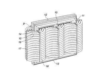
embodiment is shown in Figure 3 which shows a three-phase
laminated core transfor-mer. The core comprises, in conven-
tional manner, three core limbs 9, 10 and 11 and the
.
CA 022~6469 199X-11-23
W O 97/458~7 PCT/SE97/00875
21
retaining yokes 12 and 13. In the embodiment shown, both the
core limbs and the yokes have a tapering cross section.
Concentrically around the core limbs, the windings formed
with the cable are located. As is clear, the embodiment shown
in ~igure 3 has three concentric winding turns 14, 15 and 16.
The innermost winding turn 14 may represent the primary
winding and the other two winding turns 15 and 16 may
represent secondary windings. In order not to overload the
figure with too many details, the connections of the windings
are not shown. Otherwise the figure shows that, in the
embodiment shown, spacing bars 17 and 18 with several
different functions are located at certain points around the
windings. The spacing bars may be formed of insulating
material intended to provide a certain space between the
concentric winding turns ~or cooling, supporting, etc. They
may also be formed of electrically conducting material in
order to form part of the earthing system of the windings.