Note: Descriptions are shown in the official language in which they were submitted.
CA 02256475 2004-12-16
.7OUNI) INJULATING LAYER WITH INTEGRAL BOOT
BACKGROUND OF' THE INVENTION
FIEL1 OF THE INVENTION
This invention relates to a sound insulating layer for a vehicle, and
more particularly to a sound barner mat having an integrally formed steering
column
boot.
DESC.'RIPTION OF 'THE REL.AT1;D ART
In most contemporary automobiles, a steel fire wall separates the
engine compartment from the passenger compartment. To reduce the transmission
of
sound from the engine compartment through the fire wall and into the passenger
compartment, a sound bcuTic:r mat (otherNrisc, known as a dash mat) is
typically
1 s molded of an elastomeric material. The dash mat is mounted to and
substantially
overlies the fire wall such that an outer surface of the mat is in contact
with a bottom
surface of the vehicle carpet and extends beyond the carpet to an upper
portion of the
fire wall behind the instrumewt panel. An absorber layer, typically
constructed of an
open cell foam material, can be attached to the dash mat to interface between
the
2o sound barrier mat and,the fire wall.
Luring installation of the dash mat, an opening for the vehicle steering
column in the dash mat is aligned with a corresponding opening in the fire
wall.
Other formations in the dash mat are also aligned with various other features
on or
protmding from the fire wall. The dash rrrat is then secured to the fire wall
on the
2s passenger comp~u-tment side. A steering column is subsequently inserted
through the
aligned openings in the fire wall and dash mat. A flexible boot is installed
snugly
around the steering column and then attached to the fire wall or dash mat with
fasteners. Installation of the boot and dash mat in this manner requires a
plurality of
different parts and fasteners. The plurality of parts and fasteners results in
increased
CA 02256475 1998-11-23
WO 98/04439 PCT/US97/13154
-2-
inventory, expense, and installation time. Moreover, the seam between the boot
and
dash mat or fire wall is subject to leakage. Noise, air, water, etc. may
undesirably
transfer from the engine compartment to the passenger compartment through the
seam.
SUMMARY OF THE INVENTION
According to the invention, an acoustical barrier for mounting to a
barrier wall has a sound burner layer of a molded construction and sound
dampening
characteristics. The sound barrier layer includes an inner surface that is
adapted to
face the barrier wall and an outer surface adapted to face away from the ban-
ier wall.
1o An opening extends through the sound barrier layer between the inner and
outer
surfaces. A boot is integrally molded with the sound barrier layer and
includes a
convolute portion and a cap portion integrally molded therewith. The convolute
portion comprises a continuous outer wall section surrounding the opening. The
continuous outer wall section has an upper end integrally formed with a
flexible bight
portion, a continuous inner wall having an upper end integrally formed with
the bight
portion and a lower end integrally formed with the cap portion. The cap
portion has
an opening coincident with the opening in the sound barrier layer. Preferably,
the
boot also comprises a base having a continuous lower wall section integrally
formed
between the sound barrier layer and a lower end of the continuous outer wall
section.
The continuous lower wall section preferably projects upwardly and inwardly
from
the outer surface of the sound barrier layer toward a central axis of the
sound barrier
layer opening.
According to a further embodiment of the invention, an acoustical
burner is mounted to the f re wall of a motor vehicle. The fire wall separates
an
engine compartment from a passenger compartment and has an opening that
receives
a steering column assembly. The acoustical barrier comprises a sound burner
layer of
a molded construction and sound dampening characteristics. The sound burner
layer
has an inner surface that faces the fire wall and an outer surface that faces
away from
the fire wall. An opening extends through the sound burner layer between the
inner
3o and outer surfaces thereof and is in alignment with the opening in the fire
wall for
CA 02256475 1998-11-23
WO 98/04439 PCT/US97/13154
-3-
receiving the steering column. A boot is integrally molded with the sound
barrier
layer. The boot has a convolute portion and a cap portion integrally molded
with the
convolute portion. The convolute portion includes a continuous outer wall
section
surrounding the opening in the sound barrier layer. The continuous outer wall
section
s has an upper end integrally formed with a flexible bight portion, a
continuous inner
wall having an upper end integrally formed with the bight portion and a lower
end
integrally formed with the cap portion. The cap portion has an opening in
alignment
with the openings in the sound barrier layer and fire wall.
The continuous inner wall extends in the same general direction as the
outer wall section to form an inner channel therebetween that faces the
barrier wall.
The width of the inner channel is preferably less than a cross dimension of
the
steering column shaft to thereby prevent entry of the shaft into the inner
channel and
thus damage to the boot during installation of the steering column.
Preferably, the thickness of the convolute portion is less than the
thickness of the sound barrier layer to prevent distortion of the sound
barrier layer
during installation of the steering column. The thickness of the cap portion
and base
can also be greater than the thickness of the convolute portion.
BRIEF DESCRIPTION OF THE DRAWINGS
The invention will now be described with reference to the drawings in
2o which:
FIG. 1 is an outer perspective view of a steering column boot integrally
formed with a vehicle dash mat according to the invention; and
FIG. 2 is a cross sectional view of the steering column boot and dash
mat installed to a vehicle fire wall and steering column.
DETAILED DESCRIPTION OF THE PREFERRED EMBODIMENTS
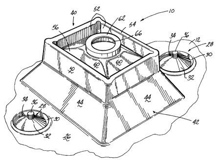
Referring now to FIGS. 1 and 2, a dash mat assembly 10 includes an
outer sound barrier layer or dash mat 12 and an inner absorber mat or layer
14. The
sound barner layer 12 is preferably formed of a filled elastomeric moldable
polymer,
e.g., elastomeric polypropylene, and is attached to a fire wall 20 of a
vehicle from the
CA 02256475 2004-12-16
passenger compartment side. The mat 12 serves as a sound barrier layer to
reduce the
transmission of'sound from the engine: compartment through the fire wall and
into the
passenger compartment of a vehicle. 'The inner absorber mat 14 is formed of a
flexible foam material, such as polyurethane, or fiberglass batting. An inner
surface
1 B of the mat 14 is typically positioned against a vehicle fire wall 20,
while an outer
surface 22 thereof faces ;am inner surface 24 of the mai 12. An outer surface
26 of the
rrvat 12 faces the underside of a vehicle carpet (not shown) and typically
extends past
the carpet behind the instrument panel.
A plw-alit~r of fasteners 28 are formed integrally with the dash mat 12
t o for securing the dash mat to the fire wall 20. Each fastener 28 comprises
a cup-shaped
dt:pression 31) that extends downwardly from the outer surface 26 of the dash
mat 12.
A conical prpjection :32 c;xtends upwaudly from the cup-shaped depression 30
and has
an opening 3~4 that extends through a central portion thereof:
A stud 36 is associated with each fastener 28 and projects outwardly
from the fire wall 20. The stud 36 is received within the opening 34 in a
friction fit
when the dash mat is in the installed position. Further details of this
mounting
arrangement can be found in U.S. Patent No. s,G01,h~)t). Althou<~h the
abcovc-c.lescrihmd nwunlirl~ arran~;crncn~.l is prcitrred, other mounting
arrangements
0111 ht; LIS~CI.
2o A steering; column boot 40 is integrally formed in one piece with the
dash mat 12 and protrude;,s outwardly from the outer surface 26. A base 42 of
the boot
40 includes a lower peripheral wall 44 that extends around the perimeter of a
steering
column opening 46 in the dash mat 12. As illustrated, the lower peripheral
wall 44
comprises four wall sections that project upwardly from the surface 26 and at
an angle
with respect thereto. fhe wall sections are continuous with each other and
with the
dash mat 12. A convolute; 48 has an outer peripheral wall 50 attached to an
inner
peripheral wall S2 through a continuous bight portion 54. The outer peripheral
wall
50 is molded between the lower peripheral wall 44 of the base 42 and the bight
portion 54, while the inner peripheral wall 52 is molded between a cap 56 and
the
3o bi.l;ht portion. The space between the outer and inner peripheral walls
forms a
CA 02256475 1998-11-23
WO 98/04439 PCT/US97/13154
-5-
continuous groove 64. The cap 56 comprises a lower peripheral cap segment 58
formed between the inner peripheral wall 52 of the convolute 48 and an upper
peripheral cap segment 60. An annular collar 62 is formed at the outer end of
the
segment 60 and has a central opening 66 that is adapted to snugly engage a
steering
column 70. The lower segment 58 extends at a smaller angle with respect to a
plane
defined by the intersection of the upper surface 26 and the lower wall 44 than
the
upper segment 60. The width of the groove 64 in the convolute is preferably
narrower
than the top 74 of a steering column shaft 72 that extends outwardly from the
steering
column 70. Although the boot with its accompanying peripheral walls and
segments
1 o are illustrated as being square-shaped, it is to be understood that
circular, triangular, or
other shapes can be formed with similar results.
During installation, the dash mat assembly 10 is placed in proximity to
the fire wall 20 and the openings 34 in the fasteners 28 are aligned with the
studs 36
protruding from the fire wall 20. Simultaneously, the opening 46 in the boot
40 is
15 aligned with an opening 78 in the fire wall 20. The absorber layer 14 is
preferably
attached to the dash mat 12 before installation in the vehicle. The fasteners
28 are
then pushed over the studs 36 to secure the dash mat 12 to the fire wall 20.
Subsequently, the steering column 70 with its accompanying shaft 72 is
inserted
through the openings 78, 46 in the fire wall and dash mat, respectively, in a
direction
2o as represented by arrow 80, from the engine compartment. Ideally, the
longitudinal
axis of the steering column shaft 72 should be positioned perpendicular to the
fire wall
20 and aligned with the central opening 66 of the collar 62 and then advanced
toward
the passenger compartment until it is completely installed. However, the shaft
72 may
not be positioned perpendicular to the fire wall and may not be aligned with
the
25 central opening 66 during assembly. In this instance, the top 74 of the
shaft 72 may
engage an inner surface of the boot 40. Since the width of the inner groove 64
in the
convolute 48 is preferably narrower than the top 74 of the shaft 72, the shaft
cannot be
inserted into the inner groove 64 as it is pushed toward the passenger
compartment
and therefore will not damage the boot. In addition, since the lower segment
58 of the
3o cap extends at a smaller angle than the upper segment 60, the shaft will
not bind at the
CA 02256475 1998-11-23
WO 98/04439 PCT/US97/13154
-6-
inner opening. The orientation of the lower and upper segments 58, 60 guides
the
shaft 72 toward the collar central opening 66. The thickness of the cap 56 and
the
base 42 is greater than the thickness of the convolute 48 to enable the boot
to flex
when shaft is installed without deforming or damaging the dash mat 12.
When installed, the integrally formed boot of the present invention
eliminates the seam and consequent seam leakage associated with the separately
installed boot of the prior art, and eliminates the need for separate boot
fasteners.
Although the invention finds particular use in automobile dash mats, it
is to be understood that the invention also finds use in other automotive or
non-
1o automotive applications wherein a panel or layer of material having an
integrally
formed boot is to be attached to a support surface. For example, a mat having
an
integrally formed boot may be installed around a gear shift lever on the floor
of a
vehicle.
Reasonable variation and modification are possible within the spirit of
15 the foregoing specification and drawings without departing from the scope
of the
invention.