Note: Descriptions are shown in the official language in which they were submitted.
CA 022~6673 1998-11-24
W 097/45342 PCT/SE97/00938
CONVEYOR BELT
The present invention relates to a conveyor belt
for conveying goods in solid or liquid state, said con-
veyor belt comprising a goods-carrying endless element
made of an elastic material, and a single belt-support-
ing wire which is fixedly connected to one lateral edgeof the endless element.
There are prior-art conveyor belts comprising a
goods-supporting endless element, which is made of an
elastic material and on which one or more force-absorb-
ing wires are arranged. This wire or these wires is/areintended for guiding and supporting the conveyor belt
by means of rollers, which determine the path of the con-
veyor belt. Owing to the elastic material of the conveyor
belt, this type of conveyor belt obtains a high flexibi-
lity, which, for instance, facilitates the manufacture ofbelt conveyors with a plurality of changes of direction
along the conveying path.
GB-A-2,205,543 discloses e.g. a conveyor belt, which
comprises a goods-carrying endless element made of an
elastic material, and a single belt-supporting wire which
is arranged along one lateral edge of the endless ele-
ment. The other lateral edge of the endless element is
pre-bent to allow it to be hooked over said one lateral
edge of the endless element with the force-absorbing
- 25 wire. This results in a closed space for conveyance of
goods. This known construction requires a great distance
between the support rollers and unhooking of the other
lateral edge from the force-absorbing wire to allow
emptying of the goods. The loading and emptying procedure
will thus be complicated in this known type of conveyor
belt.
The object of the present invention is to provide
a conveyor belt having the same flexibility as the prior-
art conveyor belts of the type stated by way of intro-
.
CA 022~6673 1998-11-24
W097/45342 PCT/SE97100938
duction, but at the same time reducing the drawbacks
connected with the prior-art conveyor belts. A further
object of the present invention is to provide a very sim-
ple conveyor belt, which may be designed for both open
and closed conveyance of goods in solid or liquid state.
According to the invention, the above-mentioned
objects are achieved by a conveyor belt of the type stat-
ed by way of introduction being given the features that
appear from the appended claim l. Preferred embodiments
of this conveyor belt are stated in the dependent claims.
According to the invention, the endless element thus
is designed such that in cross-section and in its unload-
ed state, i.e. when not affected by any external forces,
it has the form of a hook for forming a goods-receiving
space. Moreover, the endless element should have suffi-
cient rigidity in the transverse direction of the con-
veyor belt in order to essentially retain the hook shape
when conveying goods in the goods-receiving space, the
other lateral edge of the endless element being essen-
tially free, i.e. not serving any belt-supporting pur-
pose by direct coaction with support or guide rollers.
This design makes it possible to provide a belt conveyor,
which in addition to the conveyor belt re~uires a very
small number of support rollers, which coact with the
force-absorbing wire, while loading of goods into the
conveyor belt and unloading of goods from the conveyor
belt can be carried out very easil~.
In an embodiment of the conveyor belt according to
the invention, the hook shape is essentially open in the
unloaded state of the conveyor belt. This may be advan-
tageous, for instance, when conveying goods in solid
state, which may then be loaded into the goods-receiv-
ing space of the conveyor belt in essentially arbitrary
points along the conveying path.
When a closed conveyance of goods is desirable, the
inventive conveyor belt can, as an alternative, in one
embodiment have a hook shape, which is essentially closed
CA 022~6673 1998-11-24
W097/45342 PCT/SE97/00938
in the unloaded state of the conveyor belt. With this
design, it will be possible to easily effect conveyance
of goods in other directions than purely horizontal.
The closed hook shape can be achieved by a suitable
design of the endless element. A reinforcement of the
closure can be achieved by the other lateral edge of the
endless element being provided with a reinforcing ele-
ment, e.g. a wire, which like the force-absorbing wire
can be integrated with the conveyor belt and formed of
or surrounded by the material thereof.
If the other lateral edge of the endless element has
a reinforcement with a smaller degree of extensibility in
the longitudinal direction of the conveyor belt than the
elastic material, such a conveyor belt with an open hook
shape can be closed by being twisted around its longitu-
dinal direction, i.e. said reinforcement is achieved.
The invention will now be described in more detail
for the purpose of exemplification with reference to the
accompanying drawings.
Fig. 1 is a perspective view of a longitudinal part
of an embodiment of the conveyor belt according to the
present invention.
Figs 2A-F are sectional views of various embodiments
of a conveyor belt according to the present invention.
Fig. 3 is a perspective view of a belt conveyor,
which employs a conveyor belt according to the present
invention.
Fig. 4 is a perspective view o~ another belt con-
veyor, which employs a conveyor belt according to another
embodiment of the present invention.
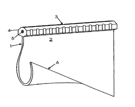
The embodiment of a conveyor belt 1 according to
the present invention as shown in Fig. 1 comprises an
elastic belt element 2 of a cross-section, which in the
~ unloaded state of the conveyor belt 1 has the hook shape
which is illustrated in the front part of the conveyor
belt 1 in the perspective view, i.e. about the same shape
as an inverted question mark. By being affected from out-
CA 022~6673 1998-11-24
W097/45342 PCTISE97/00938
side, the belt element 2 can be straightened to an essen-
tially rectilinear shape, as illustrated in the rear part
of the perspective view in Fig. 1.
At its upper lateral edge 3, the conveyor belt 1 has
a force-absorbing wire 4, which is integrated with the
belt element 2. The force-absorbing wire 4 can be made of
the same material as the belt element 2 and only have a
greater thickness than this, i.e. constitute an expanded
part of the goods-receiving endless element 2, but the
wire 4 must be relatively non-extensible in its longitu-
dinal direction to be able to serve as force absorber and
belt carrier. The wire 4 may also have a central rein-
forcement 5 in the form of a cord or the like, such that
the entire tensile force acting on and the tension in the
conveyor belt 1 are received by the reinforcement 5 and
the wire 4, respectively. As shown in Fig. 1, the wire
4 can as to its exterior, have the shape of two V-belts
arranged back to back to facilitate symmetrical engage-
ment with rollers for supporting the conveyor belt 1
and guiding the path of travel thereof. The V-belts in
Fig. 1, which are fixedly interconnected back to back,
may be toothed at their narrower portion, as shown in
Fig. 1, thereby facilitating the bending of the conveyor
belt 1 through curves.
The belt element 2, which can be made of such an
elastic material as plastic or rubber, has, however,
sufficient rigidity in the transverse direction of the
co~lve~or belt for essentially retaining, in its unloaded
and also in its goods-carrying state, the shape as shown
in the front part of the perspective view in Fig. 1.
Fig. 2 shows some different embodiments of the con-
veyor belt 1, the wire 4 being shown as a single V-belt.
The conveyor belt 1 shown in Fig. 2A corresponds to that
shown in Fig. 1. The conveyor belt 1 shown in Fig. 28
differs from that in Fig. 2A by being in its unloaded
state closed owing to the other longitudinal edge 6 of
CA 022~6673 1998-11-24
W097/45342 PCT/SE97/00938
the conveyor belt 1 engaging one side of the conveyor
belt 1.
The embodiment in Fig. 2C conforms with the embodi-
ment in Fig. 2A with the difference that an edge rein-
forcement 7 is arranged at the other longitudinal edge6 of the conveyor belt 1. This reinforcement 7 is not
intended to coact with rollers, which support or guide
the conveyor belt 1, but may be used to establish a clo-
sure of the belt by twisting it around its longitudinal
direction. An example of such use is shown with the aid
of the conveyor in Fig. 4. The edge reinforcement 7 need
not have a greater thickness than the belt element 2 and
can, in its simplest form, constitute a wearing edge,
i.e. have a greater capacity of resistance to wear than
the belt element 2.
The conveyor belt 1 shown in Fig. 2D conforms with
the one in Fig. 2B, but has the reinforcement 7 at its
longitll~in~l edge 6. This embodiment results in a slight-
ly better closure of the belt along belt portions where
the conveyor belt 1 is not twisted around its own longi-
tudinal direction.
It will be appreciated that loading of goods into
the conveyor belt 1 can take place without the shape of
the conveyor belt 1 being affected, if this is of the
type illustrated in Fig. 2A or 2C. For loading of goods
into a conveyor belt 1 of the type as shown in Fig. 2B
or 2D, a filling device is required, which opens the con-
veyor belt 1 at the other longitudinal edge 6 thereof,
thereby obtaining a passage down into the goods-receiving
space of the conveyor belt 1, and for the feeding of the
goods through the passage it is possible to use e.g. a
hopper.
For emptying the conveyor belt 1 of its goods, it
can either be stretched in the manner shown in Fig. 2E or
be guided to an inverted position, as shown in Fig. 2F.
Fig. 3 shows a very simple belt conveyor with
two deflection rollers 11 and 12, by means of which a
. . .
CA 022~6673 1998-11-24
W O 97145342 PCT/SE97100938
straight goods-conveying path is provided from the roller
11 to the roller 12 and a straight return path from the
roller 12 to the roller 11. By giving the roller 12 a
sufficiently small diameter, the conveyor belt 1 can be
made to retain an essentially completely straightened
shape when passing round the roller 12. Thus, automatic
emptying of goods is achieved when the belt has reached
the roller 12.
Such emptying of the conveyor belt 1 as shown in
Fig. 3 places relatively high demands on the material of
the conveyor belt 1 owing to its being straightened and
bent together repeatedly. By instead turning the conveyor
belt upside down a mode of emptying is achieved, which
places considerably lower ~m~n~ on the material of the
conveyor belt 1. For instance, the conveyor belt 1 can
then be made by extrusion of some suitable plastic mate-
rial, which can make the c~ e~or belt 1 extremely cheap.
Emptying the conveyor belt by turning it upside down cer-
tainly also results in an increase of the life of the
conveyor belt 1.
The conveyor belt shown in Fig. 4 utilises such a
conveyor belt 1 as shown in Fig. 2C or 2D. With a view
to determining the path of the conveyor belt 1 in Fig. 4,
use is made of a plurality of rollers having a relatively
large diameter, and the conveyor belt 1 is twisted around
its longitudinal direction in the portions between the
rollers. When the conveyor belt 1 according to Fig. 2C
or 2D is twisted around its longitudinal axis, the wire
4 and the reinforcement 7 will be twisted together like
the strands of a rope, thereby establishing a seal and
obtaining a completely closed goods-receiving space. In
this state, bulk goods can also be conveyed vertically.
In fact, the conveyed goods rotate around the longitu-
dinal axis of the conveyor belt 1 and are pressed out by
the centrifugal force towards the bottom of the hook.
~ven if the belt is positioned upside down, the goods
will not lie against the seal formed by the reinforcement
CA 022~6673 1998-11-24
W O g7/45342 PCTISE97/00938
7. For emptying the conveyor belt, use can in this case
be made of a straight stretch, where the belt is not
twisted but travels open upside down. In this position
the belt opens quite automatically.
The reinforcement 6 should be designed so as to be
stretched to about the same extent as the wire 4, but not
come into contact with the wire even when the conveyor
belt 1 is twisted.
The material of the belt element 2 must be able to
stretch so as not to absorb tensile forces in the longi-
tudinal direction of the conveyor belt l. All support and
guide rollers should be in engagement with the wire 4
only. If, as shown in Fig. 1, this has the shape of two
V ropes which are inverted towards the back, it is easy
to twist it both in right and left turns, to find room
for stands for suspension rollers and to let it enter
guide rollers. All external forces on the conveyor belt
1 are exerted via the wire 4, and owing to the symmetri-
cal appearance of the wire, the same type of support and
guide rollers can be used on both sides thereof.
It is important that the reinforcement 5 is located
in the centre of the wire 4, such that the symmetry makes
it equally easy to twist the conveyor belt 1 to the right
and to the left. When bending the wire 4 sideways, it is
desirable for it to be narrow, such that the stretching
of the material of the wire in the outer curve does not
become too great. For supporting the conveyor belt 1, it
is on the other hand advantageous if the wire 4 has as
wide a profile as possible since gravitational and cen-
trifugal forces are to be absorbed by the lower surfaces
of the wire profile on both sides of the hanging belt
element 2. One possibility is then, as shown in Fig. 1,
that the narrow sides of the wire 4 facing away from the
belt element 2 are toothed.
As described above, the emptying of the belt can
be carried out in various ways. The simplest way is to
empty the belt adjacent to such a small terminal roller
CA 022~6673 1998-11-24
W097/45342 PCTISE97100938
as the deflection roller 12 in Fig. 3. If emptying is to
take place along a straight stretch, the same principle
can be applied. Then two deflection rollers are used, the
positioning thereof being such that the conveyor belt l
follows an S-shaped path, which can extend either in the
horizontal plane or in the vertical plane.
A number of modifications of the described embodi-
ments are obviously possible within the scope of the
invention as defined by the appended claims.