Note: Descriptions are shown in the official language in which they were submitted.
CA 02257168 1999-09-02
The present invention relates to the field of dissolution testing and, in
particular, to
apparatuses for measuring heights in dissolution testing equipment.
Dissolution testing and apparatuses for performing such are known in the art.
U.S.
Patent Nos. 4,279,860 (Smolen) and 4,335,438 (Smolen) pmvide descriptions of
the art of
dissolution testing. In general, dissolutia~n testing is used to determine the
rate of
dissolution of a material in a solution, such as dissolution testing of
pharmaceuticals in
solid, semi-solid, or transdermal dosage form. For example, dissolution
testing may be
used to determine the rate of dissolution of pharmaca~ticals in~dosage form in
specific test
solutions to simulate digestion in a human. The requirements for such
dissolution testing
apparatuses are provided in United States Pharmacopeia (USP), Edition XJ~,
Section 711,
Dissolution (1990). A dissolution testing apparatus is described in U.S.
Patent No.
5,589,649, issued Dec. 31, 1996 to Brisker.
Conventional dissolution testing devices have one or more test vessels in
which test
solutions may be placed. One conventional configuration of a dissolution
tasting apparatus
has, for each test vesxl, a basket-type stirring element consisting of a metal
shaft with a
cylindrical basket at the lower end thereof. After placing the dosage to be
dissolved into
the basket, the stirring element is lowered into the test solution near the
center of the vesxl
and rotated at a specified rate (typically measured in revolutions per minute
(RP11~) for a
specified duration. Samples of the test solutions may be periodically
withdrawn from the
vessels to determine the degree of dissolution of the dosages as a function of
time.
Another conventional configuration of a dissolution testing apparatus has a
paddle-
type stirring element consisting of a metal shaft with a metal blade at the
end. In
dissolution testing with this type of apparatus, the stirring element is
rotated within the test
solution with the dosage at the bottom of the vesxl. In either conventional
configuration,
CA 02257168 1998-12-02
WO 98/05957 PCT/US97/13542
a vessel is utilized, along with a shaft having either a paddle or a basket at
the bottom end
thereof. In the present application, the term "stir element" may be used as a
general term
to refer either to a paddle or basket aff xed to the bottom end of a shaft
placeable within a
dissolution testing vessel.
When inserting the shaft with stir element into the vessel, it is important to
ensure
that there is a precise, specified distance, or height, between the bottom of
the stir element
and the inside bottom of the vessel. In the present application, the distance
between the
bottom of the stir element and the inside bottom of the vessel may be referred
to as the stir
element height or simply height. This height is an important variable that can
significantly
affect the results of a dissolution test. Incorrect distances between paddle
or basket and the
bottom of the vessel can alter the fluid hydrodynamics and distort dissolution
rates. The
USP procedure for dissolution testing provides: "The distance of 25 ~2 mm
between the
[paddle) blade [or basket) and the inside bottom of the vessel is maintained
during the
test. "
Existing devices enable the setup of this distance in each vessel, but cannot
quantify
or verify the accuracy of this critical parameter. There is a need, therefore,
for a means
for ensuring that there is a precise, specified distance between the bottom of
the stir
element and the inside bottom of the vessel.
Further objects and advantages of this invention will become apparent from the
detailed description of a preferred embodiment which follows.
2
_ ........._.. T _. ..
CA 02257168 1998-12-02
WO 98/05957 PCT/US97/13542
An apparatus for use with a dissolution testing device comprising a vessel and
a
shaft with a stir element affixed to one end thereof for placement within the
vessel. In one
embodiment, the apparatus has a front portion having a first jaw portion and a
back portion
a 5 having a second jaw portion. The front portion is slidably coupled to the
back portion, and
the first and second jaw portions form a jaw interposable between the bottom
of the stir
element and the inside bottom of the vessel. The iaw has a iaw distance
rnrrPC.,~."~;",. r~
the position of the front portion relative to the back portion. The apparatus
also includes
a shaft alignment portion for aligning the apparatus parallel to the shaft,
and a
measurement portion for providing a distance reading corresponding to the
gauge jaw
distance.
BRIEF D . RIPTION OF T~ DRAWIN
These and other features. aspects, and advantages of the present invention
will
become more fully apparent from the following description, appended claims,
and
accompanying drawings in which:
Fig. 1 is a perspective view of a gauge for measuring heights in dissolution
testing
equipment, in accordance with an embodiment of the present invention.
3
CA 02257168 1998-12-02
WO 98/05957 PCT/US97/13542
DESCRIPTION OF THE PRFFF'RRFD EMBODIM l~
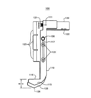
Referring now to Fig. 1, there is shown a perspective view of a gauge 100 for
measuring heights in dissolution testing equipment, in accordance with an
embodiment of
the present invention. Gauge 100 comprises a front portion 110 and back
portion 120,
which are coupled together by guide screws 131 and locking thumbscrew 130.
Front
portion 110 and back portion 120 are preferably composed of a rigid metal,
such as
stainless steel, and a relatively flat, having a preferred thickness of 1/8
inch. Front portion
110 has a jaw portion 1I5, which has a top jaw surface 116. Front portion 110
further
comprises a channel 117 and precision scale pointer 111.
Back portion 120 comprises serial number 122 etched into the top end thereof,
precision scale marks 121. and jaw portion 125, which has a bottom jaw surface
126.
Back portion 120 further comprises three angled tabs 123, each of which has a
"V" cross
section for precision placement of gauge 100 against a shaft of a dissolution
testing
apparatus, where the shaft has a stir element (i.e. basket or paddle) affixed
to the lower
end thereof, and where the shaft and stir element are for placement within a
vessel of the
dissolution testing apparatus.
Front portion 110 and back portion 120 may be slid up and down relative to one
another. along the direction of channel 117, within the limits placed by guide
screws 131
within channel 117. Gauge 100 is designed and calibrated so that there are
exactly 25mm
between top jaw surface 116 and bottom jaw surface 126 when scale pointer 111
matches
up against the "25mm" line of scale marks 121. This distance may be referred
to herein
as the gauge jaw distance. At this 25mm point, guide screws 131 are preferably
approximately at the center of the permitted travel distance within channel
117.
In one embodiment, the gauge jaw distance is adjustable between 21 and 29mm,
which corresponds to the limits of travel of front portion 110 relative to
back portion 120
and to scale marks 121. Thus. when front portion 110 is lowered as far as
possible
(relative to back portion 120), the gauge jaw distance is 2lmm and scale
pointer 111 points
to the scale mark for 2lmm. Similarly, when front portion 110 is raised as far
as possible,
the gauge jaw distance is 29mm and scale pointer 111 points to the scale mark
for 29mm.
4
..... _. 1
CA 02257168 1998-12-02
97/L35~.
194091004PCT S 11 S E P 199 v
As will be appreciated, locking thumbscrew 130, when tightened, prevents
vertical
movement along channel 117, and thus allows front portion 110 to be locked at
its current
position relative to back portion 120. Thus, thumbscrew 130 may be used to fix
the gauge
jaw distance of gauge 100. In one embodiment, thumbscrew 130 is a knurled
locking
thumbscrew, and is able to lock the gauge with a precision of within f O.Smm.
Angled
tabs 123 are preferably employed to place gauge 100 precisely in alinement
with the testing
apparatus shaft, and also allows for easy removal of the gauge without
disturbing the
current adjustment or height of the shaft within a vessel.
Height Setting
As will be appreciated, gauge 100 may be used either to accurately and
precisely
adjust the stir element height prior to a dissolution test, or to verify or
measure the stir
-' element height of a stir element already placed within a vessel. In order
to adjust the
height of a given stir element in a given vessel to a preselected height
within the range of
gauge 100, for example to 25mm, locking thumbscrew 130 is loosened slightly,
and front
portion 110 is slid relative to back portion 120 until scale pointer 111
points exactly to the
25mm scale line 121. Then, locking thumbscrew 130 is tightened to lock the
gauge jaw
distance at 25mm.
Next, gauge 100 is placed into position under the stir element, and angled
tabs 123
are positioned against the shaft. As will be appreciated, this precisely
aligns gauge 100
parallel to the center axis of the shaft. At this point, jaws 115 and 125 will
be vertically
between the bottom of the stir element and the inside bottom of the vessel.
The shaft is
gently lowered (to avoid breaking a glass vessel, for example) until top jaw
surface 116
touches the bottom of the stir element and bottom jaw surface 126 touches the
inside
bottom of the vessel. At this point, the stir element height is precisely
25mm, and the
shaft and stir element may be locked into place with a collar or other
suitable device.
Gauge 100 is then carefully manipulated (e.g., by rotation and tilting) to
remove it from
the vessel, without disturbing the shaft or its vertical placement or setting
within the vessel.
As will be appreciated, V-shaped angled tabs 123 facilitate the easy removal
of gauge 100
without disturbing the shaft adjustment.
Height Measuring
5
AMENDEa SHEEN
CA 02257168 1998-12-02
WO 98/05957 PCT/US97/13542
If a shaft and stir element are already fixedly placed within a vessel, it may
be
desirable to measure the stir element height to ensure that it is acceptable.
In order to
measure the height of a given stir element in a given vessel, locking
thumbscrew 130 is
loosened slightly, and front portion 110 is slid relative to back portion 120
to achieve the
minimum gauge jaw distance, e.g. until scale pointer 111 points to the 2lmm
scale line
121. As will be appreciated, minimizing the gauge jaw distance facilitates
moving gauge
100 into measuring position relative to the shaft and vessel.
Next, gauge 100 is placed into position under the stir element, with bottom
jaw
surface 126 placed against the inside bottom of the vessel. Angled tabs 123
are positioned
against the shaft, to precisely align gauge 100 parallel to the center axis of
the shaft. Using
one hand to hold back portion 120 down so that bottom jaw surface 126 stays in
contact
with the inside bottom of the vessel, front portion 110 is slid upwards, until
top jaw
surface 116 touches the bottom of the stir element.
At this point, the gauge jaw distance, and the corresponding scale line 121
pointed
IS to by scale pointer 111, are equal to the stir element height. Thus, the
stir element height
may be read directly from scale pointer 111 and scale lines 121. Further, if
desired,
locking screw 130 may be tightened at this point to lock in the reading
indicated by scale
pointer 111 and scale lines 121. Gauge 100 may then be rotated and tilted to
remove it
from the vessel, without disturbing the shaft or its vertical placement or
setting within the
vessel. If the measured height deviates too much from the desired height-e.g.,
if the
measured height is not between 23 and 27mm-then the height adjustment may be
determined to be in error.
Thus, as will be appreciated, gauge 100 comprises front and back portions 110
and
120, which are siidably coupled to one another. Gauge 100 comprises a jaw
means (e.g.,
jaws 115, 125) able to be interposed between the bottom of a stir element at
the end of a
shaft placed within a vessel, and the inside bottom of the vessel; the jaw
means having a
gauge jaw distance that varies as the front and back portions are slided
against one another.
Gauge 100 also comprises shaft alignment means (e.g., angled tabs 123),
preferably
formed from or affixed to back portion 120, which are used to precisely align
gauge 100
parallel to the center axis of the shaft. Gauge 100 further comprises scale or
measurement
means (e.g., scale lines 121 and scale pointer 111) that provide a measurement
or distance
6
T
CA 02257168 1998-12-02
WO 98/05957 PCT/US97/13542
reading corresponding to the gauge jaw distance. Gauge 100 also comprises
locking means
(e.g., locking thumbscrew 130) for securing front portion 110 to back portion
120 by
preventing relative sliding.
In one embodiment, scale lines 121, scale pointer 111, and serial number 122
are
4 5 permanently etched on the face of gauge 100, as illustrated, to help
reduce label tampering
or instrument drift.
It will be understood that various changes in the details, materials, and
arrangements of the parts which have been described and illustrated above in
order to
explain the nature of this invention may be made by those skilled in the art
without
departing from the principle and scope of the invention as recited in the
following claims.
7