Note: Descriptions are shown in the official language in which they were submitted.
CA 02257538 1998-12-07
- 1 -
CUTTING TOOL FOR USE IN A WELLHORE
This invention relates to a cutting tool for use in
a wellbore.
Earth-boring operations for drilling oil and gas
wells use drill strings that drill to great depths.
Typically a drilling "mud" is pumped down the drill
string for cooling the drill bit. Often there is a need
to "underream" the hole, that is to enlarge its diameter
at some location below the surface. A variety of cut
tang tools known as underreamers and hole openers have
been developed for this purpose. With such tools, the
fluid pressure of the drilling mud can be employed for
actuation. Often the drill string is withdrawn from the
hole and a suitable underreamer is installed either
alone or in series with a conventional pilot drill.
After the drill string has been inserted back into the
hole, pressurised drilling fluid is applied and, through
any of a variety of mechanisms, cutter arms on the
underreamer are urged outwardly for enlarging the selec-
ted portion of the hole. Then the cutter arms are
retracted and the underreamer is withdrawn from the
hole.
EP-A-0 298 663 discloses a cutting tool for use in
a wellbore, the tool comprising
an inner mandrel connectable to a tubular string
extending from a surface of a wellbore down to a subter-
ranean location in the wellbore,
an outer body disposed about the inner mandrel and
movable longitudinally with respect thereto, and
at least one blade pivotally mounted to the outer
body at a first location, and pivotable from a retracted
position against the outer body to a cutting position
extending from the outer body when the outer body moves
longitudinally with respect to the mandrel.
Two of the difficulties associated with known
cutting tools are the failure to underream out to a
MEN~Ep SHEET
~PE,vEP
CA 02257538 1998-12-07
- 2 -
sufficiently-large diameter and the inability to handle
relatively large torques.
According to the present invention there is provi
ded a cutting tool for use in a wellbore, the tool
comprising
an inner mandrel connectable to a tubular string
extending from a surface of a wellbore down to a subter-
ranean location in the wellbore,
an outer body disposed about the inner mandrel and
movable longitudinally with respect thereto, and
at least one blade pivotally mounted to the outer
body at a first location, and pivotable from a retracted
position against the outer body to a cutting position
extending from the outer body when the outer body moves
longitudinally with respect to the mandrel,
characterised by at least one other blade pivotally
mounted to the outer body at a second location spaced
axially from the first location,
the at least one other blade being pivotable from a
retracted position against the outer body to a cutting
position extending from the outer body when the outer
body moves longitudinally with respect to the inner
mandrel,
wherein said at least one other blade has a support
notch, and said cutting tool further comprises
a support arm pivotally connected to the outer body
and pivotable outwardly by contacting the inner mandrel
as the outer body moves longitudinally with respect to
the inner mandrel, and being movable so that a portion
thereof moves into the support notch of the blade and is
releasably held therein.
Further features are set out in Claims 2 et she
In one embodiment, the tool has an outer body
within which a mandrel is movably disposed. The mandrel
is connected at one end to an item in a tubular or drill
string, e.g. threadedly connected to a top sub having a
AMENDED S~iEET
CA 02257538 1998-12-07
- 3 -
flow channel therethrough from top to bottom which is in
fluid communication with a flow channel through the
mandrel which extends from the top to the bottom of the
mandrel.
A spring between, and biased against, the mandrel
and the outer body initially urges the outer body down
wardly with respect to the mandrel; and a plurality of
cutter arms pivotally connected to the outer body are
initially positioned against the body in a non-extended
fashion.
An open orifice at the other end of the mandrel
restricts fluid flow out from the mandrel. An increase
of fluid flow above a certain amount increases pressure
within the mandrel. When this pressure reaches a cer-
tain desired level, e.g. about 3.45 bar, pressure build-
up in a pressure chamber of the mandrel in fluid commu-
nication with the mandrel's central flow bore compresses
the spring. This results in the outer body moving
upwardly. This upward movement brings "kick-out" sur-
faces of the mandrel into contact with the pivotable
cutter arms causing them to pivot to an extended cutting
position.
One or more of the cutter arms (lower, upper, or
all) has a support which is also pivotally connected to
the mandrel and which moves out to engage and support
the cutter arm releasably. In certain embodiments a
washout port is provided through the mandrel, in fluid
communication with the central flow bore of the mandrel,
which is sized, configured, and disposed so that a
portion of the fluid flow through the central flow bore
exits through the washout port to clean the blades.
Such a port may be provided for each blade.
In certain embodiments, one or more (two, three,
four, or more) first blades of a first length are provi
ded at a first part of the tool. The or each first
blade is provided near one end of the tool. One or more
AMENDED SHEET
~PE,q~Ep
CA 02257538 1998-12-07
- 4 -
(two, three, four or more) second blades are provided at
a second part of the tool, spaced from the first part,
and the or each second blade is longer than the first
blade. In this way, the "bite" which the second blade
takes out of the tubular surround, and/or formation to
be milled or underreamed, is reduced and more-efficient
operation is achieved.
One particular tool according to the present inven
tion initially has an outside diameter of 43mm; three
first blades spaced apart 120° around the tool's circum
ference, each first blade being about 50mm long (i.e.
from pivot pin center to blade end): and three second
blades spaced apart 120° around the tool's circumfer-
ence, each second blade being about 125mm long. In this
tool, the first blades are about 170mm up from a shoul-
der on the lower end of the mandrel, about 150mm up from
the shoulder; the second blades are about 120mm up from
the shoulder; and about 100mm up from the shoulder. The
blades are offset at the different levels; i.e., in a
top view a blade appears every 60° with first and second
blades alternating. (Although it is within the scope of
this invention for the first and second blades to be
axially aligned or spaced apart angularly by any desired
amount.)
The cutting surfaces of the blades, including
bottom, side, and top surfaces, may be dressed with any
known matrix, diamond or carbide material (e. g. Klu-
strite, Zitco, Kutrite (all trademarks)), or diamond
dressing; any cutting insert may be applied to the
blades in any pattern or in any manner; or any combina-
tion thereof (all collective referred to as "cutting
material").
The inner mandrel has kick-out surfaces disposed so
that only one set of blades is initially extended and
then, with increased fluid pressure and resulting addi
tional outer body movement, the second set of blades is
:~~~~~r.~r)c~ ~i-~~-f
v m L
~kr'~C~r~'P
CA 02257538 1998-12-07
- 5 -
extended. Accordingly, in a tool with three or more
blade sets, the sets can be extended either simultan-
eously or sequentially.
Once the blades are extended, cutting, milling
and/or underreaming ie initiated by rotating a drill
string to which the tool is connected, or by activating
a down-hole motor to which the tool is connected. Any
system or apparatus for orienting a down-hole tool, and
for indicating the position of a down-hole tool, may be
used with a tool according to the present invention.
In certain embodiments, with two or more sets of
blades at different heights on the tool, all the blades
are the same length and extend outwardly from the tool
the same distance. In other embodiments blades at one
location are longer than blades at a different location.
In one embodiment, some blades in one set are the same
length as blades in another set and some of the blades
are longer than the other blades. In one embodiment
blades in one set which are the same length as blades in
another set alternate with blades of longer length, e.g.
around the tool's circumference at one location a short-
er blade is between two longer blades, etc., e.g. in one
embodiment one blade is about 2.5mm shorter than an
adjacent blade.
30
AMENDED SHEET
i F'F:4/E-P
CA 02257538 1998-12-07
- 6 -
The present invention will now be described by way
of example with reference to the accompanying drawings,
in which:
Fig. lA is an axial cross-sectional view of a
cutting tool according to the present invention;
Fig. 1B is a cross-sectional view along line 1B-1B
of Fig. lA;
Fig. 1C is a cross-sectional view along line 1C-iC
of Fig. lA;
Fig. 2A is a view of the tool of Fig. lA in a
different position;
Fig. 2B is a cross-sectional view along line 28-2H
of Fig. 2A;
Fig. 2C is a cross-sectional view along line 2C-2C
of Fig. 2A;
Fig. 2D is a cross-sectional view along line 2D-2D
of Fig. 2A;
Fig. 2E is a side view of a blade of the tool of
Fig. 2A; and
Fig. 2F is a bottom view of the blade of Fig. 2E.
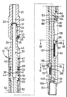
Referring now to Fig. 1, a tool 10 according to the
present invention has a top sub 20 threadedly connected
to a mandrel 30 about which is movably disposed a con-
nector 40 to which is threadedly connected an outer body
50. A first set of blades 60 is pivotally connected to
the outer body 50 at one location on the outer body 50,
and a second set of blades 70 is pivotally connected to
the outer body 50 at a second location spaced axially
from the first location. The blades 70 are shorter in
length than the first blades 60. Blade supports 80
support the first blades 60 when they are extended.
The top sub 20 is connectable to any typical member
of a tubular or drill string, such as a mud motor, a
measurement-while-drilling system, or a shock sub.
The top sub 20 has an upper (as viewed) externally
screw-threaded end 21, and a lower internally screw-
~~,II~IV~E~ ~!--1EE'~
a r, _-_ ; ; 1. ~ r'e
5~ c_. w:
CA 02257538 1998-12-07
- 7 -
threaded end 22. A flow bore 23 extends from one end of
the sub to the other. A locking screw 24 in a bore 25
extends into a groove 35 of the mandrel 30 to prevent
the sub from separating from the mandrel.
The mandrel 30 has an upper externally screw-threa-
ded end 31, with an O-ring 32 in a recess 34 to seal the
mandrel/sub interface. A flow restrictor, or choke 149,
is secured in a recess 36 at the down-hole end of the
mandrel and is held in place by a snap-ring 37. An O-
ring may be used between the choke and the surface of
the mandrel. The choke may be any size to restrict to a
desired extent the flow of fluid from the mandrel. As
shown, the choke has s central bore the same diameter as
the narrower bore through the mandrel but the bore
through the choke may be smaller in diameter than the
bore through the mandrel. A port 38 permits fluid
flowing through bore 33 to flow from within the mandrel
30 into a chamber 41 formed by the mandrel 30 and the
connector 40. The lower flow bore 39 is of a lesser
diameter than that of the upper flow bore 33. O-rings
131, 132 seal the mandrel/outer body interface. A
shoulder 133 provides a surface against which a spring
is seated. A kick-out surface 134 is positioned adja-
cent each blade support 80: a kick-out surface 135 is
positioned adjacent each blade 60, and a kick-out sur-
face 136 is positioned adjacent each blade 70. A wash-
out port 137 for fluid flow to the blades is positioned
adjacent each blade 60, and a washout port 138 for fluid
flow to the blades is positioned adjacent each blade 70.
The connector 40 has a lower screw-threaded end 41
threadedly connected to the outer body 50. An O-ring 42
seals the connector/outer body interface. A skirt 44
defines part of the chamber 41. A central bore 43
extends through the connector 40 from one end to the
other.
The outer body 50 has an upper screw-threaded end
AMENDED SHEET
IPEA/EP
CA 02257538 1998-12-07
51 which is threadedly connected to the lower screw-
threaded end 41 of the connector 40. 0-rings 151, 152
seal the mandrel/outer body interface. A spring 52 is
biased against the shoulder 133 of the mandrel 30 and
against a shoulder 54 of the outer body 50. Initially
this spring urges the outer body 50 downwardly with
respect to the mandrel 30 and maintains these parts in
the position shown in Fig. lA.
Each blade support 80 is pivotally mounted to the
outer body 50 with a pivot pin 55. A holding pin 86 in
a channel 87 holds the pivot pin 55. Each blade 60 is
pivotally mounted to the outer body 50 with a pivot pin
58. A holding pin 66 in a channel 67 holds the pivot
pin 58. Each blade 70 is pivotally mounted to the outer
body 50 with a pivot pin 59. A holding pin 76 in a
channel 77 holds the pivot pin 59.
A bore 53 extends through the outer body 50 from
one end to the other. A lower end 157 of the outer body
50, having a shoulder 158, is connectable to any typical
member of a drill string, tubular string, or string with
a down-hole or mud motor.
Each blade 60 (see Figs. lA, 2E and 2F) has a
cutter face 61, an end face 62, a shoulder face 63, a
back face 64, a torque notch 65 and a pivot pin hole 68.
As shown, the blades 60 have a crushed carbide cutting
matrix 69 on the face 61 and part of the end face 62.
Of course, the entire blade may be covered with such a
matrix. Cutting inserts may be positioned in one or
more faces in any disposition, pattern or array for such
inserts as known for drilling, milling, or reaming
tools, with or without chipbreakers on each insert.
As shown in Fig. 2A, fluid under pressure (e. g.
drilling fluid, mud, water, etc.) flowing through the
tool 10 may increase pressure within the chamber 41 to
such a level that the force of the spring 52 is overcome
and the connector 40 and outer body 50 moved upwardly
~~lu~isDED SHEF~
IPEa/CP
CA 02257538 1998-12-07
- g -
with respect to the mandrel 30. This movement brings an
end of each blade support 80 into contact with its
respective kick-out surface 134, forcing each blade
support 80 outwardly.
Upward movement of the outer body 50 also brings an
end of each blade 60 into contact with its respective
kick-out surface 135, forcing each blade 60 outwardly.
The end of each blade support 80 moves into a torque
notch 65 of its respective blade 60 to stop further
pivotal movement of each blade 60 and to support each
blade 60 during cutting.
Upward movement of the outer body 50 also brings an
end of each blade 70 into contact with its respective
kick-out surface 136, forcing each blade 70 outwardly.
Pivotal movement of each blade 70 ceases when it abuts a
stop surface 159 of the outer body 50.
As shown in Fig. 2A, each blade 60 is positioned so
that fluid flowing from the washout ports 137 flushes
material away from the blade. Each blade 70 is posi-
tinned so that fluid flowing from the washout ports 138
flushes material away from the blade. As shown in Figs.
2B and 2C the blades 60 are 60° offset from the blades
70.
When the fluid pressure in the tool is reduced, the
spring 52 urges the outer body downwardly, and the
blades are retracted. Alternatively, by an upwards pull
applied to the top sub 20 and mandrel 30, the blade
supports 80 and blades 60, 70 may be moved off their
respective kick-out surfaces and pivot back into the
outer body 50.
In one typical operation of the tool 10, the tool's
upper end is connected to a mud motor, and the tool's
lower end is connected to a mill or bit. The tool is
passed through a tubing string with a relatively small
inner diameter and into a casing of larger diameter.
The blades are extended and reaming commences. Upon
AMENDED SHEET
IPEA/EP
CA 02257538 1998-12-07
- 10 -
completion of the reaming operation, the blades are
retracted and the tool is removed from the wellbore.
In certain "through-tubing" applications, the tool
is sized so that, initially, it can be inserted
5 through tubing, e.g. tubing with an inside diameter of
50.7mm.
15
25
35
f,"~,n~3~~ ~~D SHEET
1°E~/E~