Note: Descriptions are shown in the official language in which they were submitted.
CA 02257738 1999-O1-04
LIQUID DISPENSER AND APPLICATOR
FIELD OF THE INVENTION
The invention relates to the field of liquid dispensers and applicators and
more particularly to dispensers and applicators such as might be used, for
example, for
storing and handling various liquids including liquid cosmetics or medical
ointments.
BACKGROUND OF THE INVENTION
Various types of cosmetic make-up are available. Types of cosmetic
make-up include pressed powder, creme and liquid make-up. One of the
advantages
of liquid make-up over creme or pressed powder make-up is that liquid make-up
is
generally easier to blend onto a user's skin than either pressed powder or
creme.
Liquid foundation is one type of liquid make-up. Liquid foundation generally
has a thick
or pasty consistency which gives the liquid foundation good coverage on a
user's skin.
Liquid foundation allows for quick application to the user's skin and may also
include
moisturizers and ingredients which provide protection from harmful solar rays.
Various methods are available for applying liquid foundation ranging from
simply using one's finger tips to the use of various types and styles of foam
blending
pads specifically designed for the application of cosmetics. Such foam
blending pads
are popular applicators for liquid foundation as they provide a convenient
application
method for the liquid foundation which is generally less messy than using
fingers.
Typically, the liquid foundation is applied to the foam applicator by pouring
small
amounts of foundation from a bottle containing the foundation onto a surface
of the
foam applicator. The foam applicator is then used to blend the liquid
foundation onto
the skin of the user.
The use of a foam applicator for the application of liquid foundation also
presents disadvantages. First, the foam applicator may be unhygienic,
particularly if
-1 -
CA 02257738 1999-O1-04
used repeatedly, as it may pick up dust, dirt and liquids. Foam applicators
have a
tendency to become dirty easily. Foam applicators are often left on counter
tops or
near sinks where they are exposed to dust, liquids and other unsanitary
substances.
These particles of dirt may end up on a user's skin and clog the user's pores
causing
blemishes, pimples or infections. For this reason, it is often recommended to
dispose
of a foam applicator after one application of liquid foundation or
alternately, thoroughly
to wash, to dry and then properly to store the foam applicator to avoid
contamination.
Disposal of used foam applicators and the need to maintain a supply of new
foam
applicators may be inconvenient or expensive, or both. Therefore, users
typically throw
out foam applicators only after several applications. It may be inconvenient
or
impractical for a user to take multiple foam applicators with them when going
out in
order to reapply or touch up their make-up.
Furthermore, although foam applicators are generally less messy than
using finger tips, liquid foundation has a tendency to seep through the foam
applicator
and may soil a user's hands when the foam applicator is being used. Hand
washing
is thus often necessary after each use of a foam applicator to avoid the
potential of
soiling clothes and other items from the user's dirty hands. Often a user may
wish to
apply or touch up their make-up at a time or place when they do not have
access to the
necessary facilities for washing their hands. For this reason, a foam
applicator is often
inconvenient and may result in a user choosing another form of foundation
which,
although not as effective as liquid foundation, is not as messy.
Where a foam applicator is used with a bottle of liquid foundation, the
foam applicator may contaminate the contents of the bottle. For example, if
foundation
is applied to a previously used foam applicator by covering the opening of the
bottle
with the foam applicator and then tipping the bottle upside down, contaminants
on the
foam applicator may be transferred to the contents of the bottle.
Another disadvantage of foam applicators heretofore has been their
tendency to soil the interior of a handbag or pocket unless properly
protected. In the
-2-
CA 02257738 1999-O1-04
past, foam applicators were sometimes carried in small plastic bags or make-up
bags.
These methods for storing foam applicators do not prevent the foundation from
smearing on the inside of the plastic bag or make-up bag or on their other
contents.
Thus, there is a need for a hygienic liquid foundation applicator which
reduces the mess caused by conventional foam applicators. In addition there is
a need
for a portable system for dispensing and applying liquid foundation.
SUMMARY OF THE INVENTION
According to one aspect of the invention, a liquid dispensing apparatus
has a reservoir for containing a liquid, and a spout whence to dispense the
liquid. An
applicator is attached to the reservoir for receiving the liquid from the
spout. The
applicator is detachable from the reservoir to permit the applicator to be
used to apply
the liquid to a surface.
According to another aspect, the invention provides a liquid dispenser
having a reservoir for containing a liquid for application to a surface. An
applicator
holder is attachable to the reservoir and detachable therefrom. The reservoir
has a
spout for dispensing the liquid onto an applicator element held by the
applicator holder.
According to a further aspect, the invention provides a liquid dispensing
apparatus having a reservoir for containing a liquid for application to skin
and having
a spout through which to dispense the liquid. A lid is attachable to the
reservoir for
enclosing the spout . An applicator is attached to the lid and is detachable
therefrom.
When the applicator is attached to the lid and the lid is attached to the
reservoir, the
applicator is enclosed by the lid.
According to a still further aspect, the invention provides an applicator
having a handle and a transport element. The handle has a surtace for a user
to grasp
and a seat. The transport element is formed to engage the seat.
-3-
CA 02257738 1999-O1-04
According to yet another aspect, the invention provides an apparatus having a
sheath with an open end. An applicator for receiving a liquid and applying the
liquid
to a surface is slidably receivable in the sheath and is movable from the
interior of the
sheath to emerge from the open end of the sheath. The liquid is dispensed onto
the
applicator when the applicator is emerged from the sheath, and the liquid is
applied to
the surface with the applicator by a user holding the sheath.
The apparatus may have a cover for closing the open end of the sheath when
the applicator is enclosed in the sheath. The applicator may include a sponge
holder
and a sponge attached to the sponge holder. A track may be provided on an
interior
wall of the sheath. The sponge holder may have a foot corresponding to the
track to
be slidably receivable therein.
BRIEF DESCRIPTION OF DRAWINGS
Preferred embodiments of the present invention will next be described for
purposes of illustration and not of limitation, all by reference to the
following drawings
in which:
Figure 1 is a three-quarter view of an example of a liquid dispenser and
applicator according to a preferred embodiment of the present invention;
Figure 2 is a three-quarter view of the liquid dispenser and applicator of
Figure 1 with a lid;
Figure 3a is an exploded view of the reservoir and pump of the dispenser
and applicator of Figure 1;
Figure 3b is a three-dimensional view of the sponge holder of the liquid
dispenser and applicator of Figure 1;
Figure 4 is a bottom view of the sponge holder of the liquid dispenser and
applicator of Figure 1;
Figure 5 is a side view of the reservoir, sponge and sponge holder of the
liquid dispenser and applicator of Figure 1 as viewed on Arrow "5";
-4-
CA 02257738 1999-O1-04
Figure 6 is a top view of the pump and reservoir of the liquid dispenser
and applicator of Figure 1;
Figure 7 is a cross-sectional view of the reservoir and pump of Figure 6
taken on Section "7";
Figure 8 is an isometric view of an example of a liquid dispenser and
applicator according to a first alternative embodiment of the present
invention;
Figure 9 is an isometric view of an example of a liquid dispenser and
applicator according to a second alternative embodiment of the present
invention;
Figure 10 is a three-quarter view of a sponge holder according to a third
alternative embodiment of the present invention;
Figure 11 is an isometric view of an applicator according to a fourth
alternative embodiment of the present invention;
Figure 12 is an isometric view of the applicator of Figure 11;
Figure 13 is a top view of the sponge holder and sheath of the applicator
of Figure 1 as viewed on Arrow "13";
Figure 14 is a side view of the applicator of Figure 11 as viewed on
Arrow "14"; and
Figure 15 is a side view of the applicator of Figure 11 as viewed on
Arrow "15".
DETAILED DESCRIPTION OF PREFERRED EMBODIMENTS
The description which follows, and the embodiments described therein,
are provided by way of illustration of an example, or examples of particular
embodiments of the principles of the present invention. These examples are
provided
for the purposes of explanation, and not of limitation, of those principles
and of the
invention. In the description which follows, like parts are marked throughout
the
specification and the drawings with the same respective reference numerals.
The
drawings are not necessarily to scale and in some instances proportions may
have
been exaggerated in order more clearly to depict certain features of the
invention.
-5-
CA 02257738 1999-O1-04
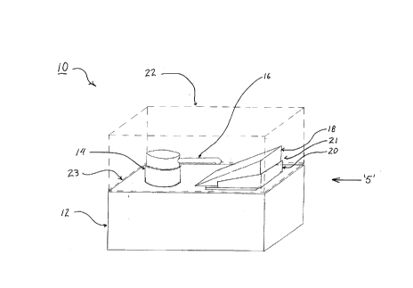
Figure 1 shows a preferred embodiment of a liquid cosmetics dispenser
and applicator indicated generally as 10, according to the principles of the
present
invention. Dispenser and applicator 10 has a reservoir 12 having a pump 14
mounted
on the top of reservoir 12. Reservoir 12 contains a liquid such as liquid
foundation
which may be pumped from reservoir 12 using pump 14. When pump 14 is pumped,
the liquid contained in reservoir 12 is dispensed from reservoir 12 via a
discharge outlet
in the nature of a spout 16 of pump 14. The tip of spout 16 is positioned over
a
cosmetic application element in the nature of a sponge 18, mounted to an
element
carrier in the nature of a sponge holder 20. Together sponge 18 and sponge
holder 20
serve as an applicator 21 for applying the liquid foundation to a user's skin.
In the
preferred embodiment, sponge 18 is glued to sponge holder 20 with an adhesive
which
allows sponge 18 to be removed from sponge holder 20 and replaced with a fresh
sponge. Alternatively, sponge holder 20 may be sized relative to sponge 18 to
hold
sponge 18 with a friction fit, sponge 18 is preferably wedge shaped as shown
in Figure
1, but it may have other shapes which may be considered useful or expedient in
the
circumstances. The invention is not limited to sponges but may include other
types of
liquid applicators such as fabric pads, porous membranes or webs or cotton
balls.
Instead of having pump 14 for dispensing liquid foundation, reservoir 12
may have a simpler means for dispensing the liquid foundation such as a
bottleneck
with a screw top or a simple spout through which the liquid foundation may be
poured.
Where a pump or similar means is supplanted by a pouring spout, the liquid
foundation
can be dispensed from reservoir 12 by tipping reservoir 12 to permit gravity
to cause
the liquid foundation to be dispensed from the bottleneck or spout. Pump 14 is
the
preferred means for dispensing the liquid foundation from reservoir 12 as it
will tend to
reduce or discourage a mess from forming and does not require a cap or lid to
discourage or prevent the unwanted escape of liquid foundation therefrom. Pump
14
also aids to prevent the contamination of the liquid contained in reservoir 12
from
sponge 18. For this reason, spout 16 preferably does not contact sponge 18
when
dispenser and applicator 10 is used.
-6-
CA 02257738 1999-O1-04
Sponge holder 20 is detachable from reservoir 12 to permit it to be used
to apply the liquid foundation. Referring to Figures 1 and 2, dispenser and
applicator
may also have a lid 22 which fits onto the reservoir 12 to enclose pump 14,
sponge
18 and sponge holder 20. Lid 22 is shown in Figure 1 in dotted lines so as not
to
5 obscure the view of the pump 14, sponge 18 and sponge holder 20. Figure 2
shows
dispenser and applicator 10 with lid 22 in place on reservoir 12, enclosing
pump 14,
sponge 18 and sponge holder 20. Lid 22 is preferably hingedly attached along
one of
its bottom edges to a top edge of the reservoir 12 to enable dispenser and
applicator
10 to be hingedly opened and closed along a hinged edge 23 to expose pump 14,
10 sponge 18 and sponge holder 20 without having fully to separate lid 22 from
reservoir
12. Alternatively, lid 22 may be fitted to reservoir 12 with a friction fit, a
snap fit, or a
detent to prevent lid 22 from freely falling off of reservoir 12 when in
place. Other
means are possible for attaching lid 22 to the reservoir 12 to enclose pump
14, sponge
18 and sponge holder 20.
Referring now to Figures 3a and 3b, reservoir 12, pump 14 and sponge
holder 20 may be viewed in their disassembled state. Pump 14 has a tube 24
connected to spout 16 to provide a conduit for supplying liquid from reservoir
12 to
spout 16. Reservoir 12 has a reservoir opening 26 for receiving tube 24 of
pump 14.
When assembled, pump 14 is preferably permanently affixed or glued to provide
a seal
about reservoir opening 26. Alternatively, reservoir 12 may include a threaded
neck
surrounding the reservoir hole 26 onto which pump 14 may be screwed to be
removably
attached thereto. In such a case, pump 14 would be correspondingly threaded to
mate
with the neck of reservoir 12. With pump 14 being removable the user is able
to refill
reservoir 12 with liquid foundation when the original supply is exhausted.
Other
methods for attaching pump 14 to reservoir 12 are possible.
Referring now to Figures 3a, 3b, 4 and 5, sponge holder 20 has a mount,
or seat, in the nature of a cradle portion 30 for receiving and holding sponge
18. In the
preferred embodiment, cradle portion 30 is sized to fit a foam wedge having a
rectangular base with a length of approximately two inches and a width of
-7-
CA 02257738 1999-O1-04
appr~~ximately one inch. Thus, cradle portion 30 has similar dimensions to
accommodate the base of the foam wedge. Sponge 18 is preferably made from a
latex
foam. However, other materials may alternatively be used for sponge 18.
Sponges
may :~Iso come in other shapes and sizes. For example sponge 18 may
alternatively
be a rectangular block or may have a rounded or bulbous end.
Sponge holder 20 also has a foot 34 on the underside of cradle portion
30. f=oot 34 protrudes from cradle portion 30 and has a pair of substantially
parallel,
spacad apart flanges 36, 38. Referring additionally to Figure 6, reservoir 12
has a
shoe, socket or guideway in the nature of a track 40. Flanges 36, 38 act as
guide
follo~n~ers by which foot 34 slidably engages track 40. Track 40 includes a
first edge 42
and ~~ second edge 44 on either side, each having a flange 46, 48 which
corresponds
to flanges 36, 38 on foot 34 of sponge holder 20. The width of the channels
formed
betwE~en flanges 46, 48 and the top surface of reservoir 12 is slightly
greater than the
thickness of flanges 36, 38 such that foot 34 may be received in track 40 with
a friction
fit. This prevents sponge holder 20 from freely sliding out of track 40. Track
40 also
has ~~ stop 50 at the end of track 40 which is proximate to pump 14 to arrest
the sliding
of sponge holder 20 when foot 34 contacts stop 50.
The distal ends of flanges 46, 48 are preferably shaped so as not to
presE~nt right angles at the ends of flanges 46, 48. The slanted ends of
flanges 46, 48
tend ro guide flanges 36, 38 of foot 34 into the channels of track 40 provided
at the first
edge 42 and second end 44.
Other means are possible for attaching sponge holder 20 to reservoir 12
such that it is detachable therefrom. For example, foot 34 and track 40 could
be
replaced by strips of Velcro T"" with one portion of a hook and loop fabric
strip fastening
systEm attached to the bottom of sponge holder 20, while a corresponding
portion is
attached to the top surface of reservoir 12. The first fabric strip can be
glued to the
bottom of the sponge holder 20 and the second fabric strip can be glued to the
top
_g_
CA 02257738 1999-O1-04
surface of the reservoir 12. The first fabric strip releasably adheres to the
second
fabric strip when the strips are pressed together.
Referring to Figures 1 and 6, when sponge 18 and sponge holder 20 are
attached to reservoir 12, a portion of sponge 18 is preferably positioned
under spout
16. When liquid foundation is pumped from reservoir 12, it is dispensed from
pump 14
through spout 16 directly onto sponge 18. When sufficient liquid foundation
has been
dispensed onto sponge 18, sponge holder 20 and sponge 18 can be slidably
detached
from reservoir 12 and can then be used to apply the liquid foundation to a
user's skin.
In addition to providing a means for attaching sponge 18 to reservoir 12,
sponge holder
20 also serves as a holder or handle which the user may grasp when applying
the liquid
foundation with sponge 18. By holding onto sponge holder 20, the user can
avoid
directly touching sponge 18 and can thereby tend to avoid soiling his or her
fingers with
liquid foundation that may seep through sponge 18.
Sponge holder 20 also provides a stiff support for sponge 18 which may
tend to facilitate application of the liquid foundation to be applied to a
user's face.
Referring to Figures 1 and 2, lid 22 provides a protective covering for
pump 14, sponge 18 and sponge holder 20. Thus, lid 22 prevents dust and other
contaminants from contacting sponge 18. By keeping sponge 18 relatively clean,
sponge 18 may be used for a greater number of applications than an unprotected
sponge which might be exposed to liquids and airborne contaminants such as
dust and
dirt. In addition, lid 22 provides a protective covering for pump 14, sponge
18 and
sponge holder 20 such that the risk of soiling other articles and personal
effects with
liquid foundation is reduced when the entire dispenser and applicator 10 is
placed into
a user's purse, handbag or luggage.
When the user has used sponge 18 for a number of applications such that
sponge 18 requires replacing, the user can remove sponge 18 from sponge holder
20
and place a fresh sponge 18 into cradle portion 30. Sponge 18 is preferably
held in
_g_
CA 02257738 1999-O1-04
sponge holder 20 by glue. The glue used in sponge holder 20 preferably has
certain
adhesive properties which make the glue reusable such that after sponge 18 is
removed from sponge holder 20 the glue is capable of receiving and adhering to
a fresh
replacement sponge. Sponge 18 may alternatively be attached to sponge holder
20
with double sided adhesive tape, a friction fit, a clip or other means.
Sponge 18 may alternatively be permanently affixed to sponge holder 20
such that applicator 21 is an integrated device. When applicator 21 becomes
worn out
or too dirty, the entire applicator may be replaced, not just sponge 18.
The dispenser and applicator 10 preferably has dimensions which make
it practical for a user to treat the dispenser and applicator 10 as a portable
item. In the
preferred embodiment of Figure 1 the dimensions are 1'~4 inches x 3'/ inches x
1 inch
for dispenser and applicator 10. Reservoir 12 preferably has an interior
volume of
approximately 30 to 35 ml, or approximately one fluid ounce, such that
reservoir 12 is
capable of holding the contents of a standard, one fluid ounce bottle of
liquid
foundation. This volume for reservoir 12 also enables dispenser and applicator
10 to
have a manageable size which contributes to the portability of dispenser and
applicator
10. Reservoir 12 may be made smaller to make dispenser and applicator 10 more
discrete and portable in a small hand bag or even a pocket. Dispenser and
applicator
10 could alternatively be made on a larger scale for use on a vanity or
counter-top
where portability is not a concern.
Sponge holder 20, reservoir 12, pump 14 and lid 22 may all be made of
plastic. Various types of plastic may be used, with each type having its
relative
advantages and disadvantages. Where reservoir 12 does not include a pump, the
plastic used for the reservoir 12 may be flexible such that liquid foundation
may be
dispensed by the user tipping and squeezing reservoir 12.
Referring now to Figure 7, the interior of reservoir 12 includes a sloping
bottom or a sump 52 such that liquid foundation contained therein will collect
in
-10-
CA 02257738 1999-O1-04
reservoir 12 near tube 24 of pump 14. Sump 52 encourages liquid foundation to
pool
in the area of tube 24 when the supply of liquid foundation in reservoir 12 is
nearly
exhausted. By pooling around tube 24, a greater amount of liquid foundation
can be
more efficiently extracted by the user before having either to dispose of
dispenser and
applicator 10, or, where reservoir 12 is refillable, to refill reservoir 12.
Where pump 14 is removable from reservoir 12, reservoir 12 may be
refilled when the supply of liquid foundation contained therein has been
exhausted.
The liquid foundation is preferably contained in reservoir 12 directly. In
other
alternative embodiments, a plastic bag or bladder removable from reservoir 12
may be
provided to hold the liquid foundation. The bag or bladder could be
replaceable such
that when the supply of liquid foundation in the bag is exhausted, the bag or
bladder
is replaced. The advantages of storing the liquid foundation in a bag or
bladder is that
the mess created when refilling reservoir 12 may tend to be reduced. In
addition, the
exhausted bladder may be removed from reservoir 12 and squeezed so as to
remove
a higher proportion of the liquid foundation before disposing of the bladder.
This is
particularly advantageous because of the cost of liquid foundation, which may
be
considerable for premium brands of cosmetics.
Alternate designs and shapes for dispenser and applicator 10 are
possible. For example, in Figure 8, a dispenser and applicator 60 having a
more
rounded design is shown. Dispenser and applicator 60 has similar functional
features
as dispenser and applicator 10 shown in Figures 1 to 7 such as a reservoir 62,
a pump
64 with a spout 66, a sponge 68, a sponge holder 70 and a lid 72. Reservoir 62
has
a track 74 in which sponge holder 70 is slidably received. Track 74 has a
dovetail
shape and receives a foot (not shown) of sponge holder 70 which is
correspondingly
dovetail shaped. Track 74 also has a stop 76 which arrests the sliding of
sponge
holder 70 when the foot (not shown) of sponge holder 70 contacts stop 76.
The more rounded design of dispenser and applicator 60 may provide
several advantages. The rounded edges may make the reservoir 62 and lid 72
more
-11 -
CA 02257738 1999-O1-04
durable and less likely to chip or break. The rounded design may also
facilitate
production in an injection moulding manufacturing process.
Referring to Figure 9, another alternative embodiment of the invention is
shown. A dispenser and applicator 80 similar to dispenser and applicator 60 of
Figure
8 is shown. Dispenser and applicator 80 has a reservoir 82, a sponge 88, a
sponge
holder 90 and a lid 92 which are similar to the corresponding features of
dispenser and
applicator 60. However, instead of having a pump, dispenser and applicator 80
has a
threaded bottleneck 94 and a cap 96. The interior walls (not shown) of cap 96
are
correspondingly threaded to mate with the threads on bottleneck 94. Thus, cap
96 may
be screwably attached to bottleneck 94 in order to seal reservoir 82. To use
dispenser
and applicator 80, cap 96 is unscrewed from bottleneck 94 to open reservoir
82. The
user slidably removes sponge holder 90 and sponge 88 from reservoir 82 and
then tips
reservoir 82 to dispense liquid foundation onto sponge 88 through bottleneck
94. The
dispensing of liquid foundation from reservoir 82 is aided by gravity which
draws liquid
foundation to bottleneck 94 when reservoir 82 is tipped. Sponge 88 and sponge
holder
90 may then be used to apply the liquid foundation to a user's skin. When the
application is completed, sponge 88 and sponge holder 90 may be replaced onto
reservoir 82 and cap 96 may be screwed back onto bottleneck 94. Dispenser and
applicator 80 may be less expensive to manufacture than dispenser and
applicator 60
as a result of using bottleneck 94 and cap 96 instead of a pump.
Although described above in connection with a dispenser for liquid
foundation, it will be appreciated that a sponge holder may be useful on its
own for
protecting the fingers of a user from becoming soiled by liquid foundation
dispensed
from other types of foundation dispensers and containers. Thus, it will be
appreciated
that applicator 21 of Figure 1, which includes sponge 18 and sponge holder 20,
may
be used in connection with other types of liquid foundation dispensers. For
example,
applicator 21 can be used with a conventional bottle of liquid foundation as
is readily
available at cosmetics counters and at drugstores.
-12-
CA 02257738 1999-O1-04
Referring to Figure 10, a simplified sponge holder 120 is shown for use with a
wide variety of types of liquid foundation dispenser. Sponge holder 120 has a
base
122 to which a sponge 118 (shown in dotted line) can be affixed by a clip,
friction fit,
glue, tape or other means. Sponge 118 is preferably glued to sponge holder
120. The
shape of base 122 of sponge holder 120 is preferably rectangular to
accommodate the
rectangular base of a conventional foam wedge. Sponge holder 120 also has two
side
walls 124, 126 and a back wall 128. The dimensions of sponge holder 120
correspond
to the size of sponge 118. Side walls 124, 126 and back wall 128 preferably do
not rise
to the height of sponge 118 such that more of sponge 118 is exposed and may be
used
for applying the liquid foundation. It is also important for the walls 124,
126, 128 to be
low so that they do not scratch the user's skin when sponge holder 120 is
used.
A user may handle sponge 118 by touching only sponge holder 120 with
his or her fingers. Liquid foundation may be dispensed onto sponge 118
according to
various known methods and applied to the user's skin with sponge 118 without
any
contact between sponge 118 and the user's fingers. Thus, sponge holder 120 may
tend to reduce or eliminate soiling of a user's fingers from the seepage of
liquid
foundation through sponge 118.
Sponge holder 120 may also protect sponge 118 from contamination by
liquids. When sponge 118 is placed on a counter, sink or other surface, sponge
holder
120 will protect the bottom of sponge 118 from water or other liquids present
on such
surface.
Referring to Figure 11, an applicator 210 according to another alternative
embodiment of the invention has a sponge holder 220 which is provided with a
housing
in the nature of a protective sheath 222 and a cap 224. The sponge holder 220
may
slide in and out of sheath 220 when cap 224 is removed. Like previously
described
embodiments of the invention, sponge holder 220 is sized to hold a sponge such
as a
standard sized foam wedge.
-13-
CA 02257738 1999-O1-04
Referring to Figure 12, cap 224 fits onto sheath 222 to enclose sponge
holder 220 and the sponge.
Referring to Figures 13, 14 and 15, a sliding carrier in the nature of a
sponge holder 220 has a foot 234 with a dovetail shape for sliding engagement
within
a mating track 240 provided on an inside wall of sheath 222. Foot 234 and
track 240
are sized such that sponge holder 220 may slide between a retracted, storage
position
within sheath 222, and an extended position for use in which sponge holder 240
stands
outwardly, or proud of, the opening of sheath 222. The preferred shape for
foot 234
and track 240 is the corresponding dovetail shape. However, other shapes for
foot 234
and track 240 may be used. A slit 242 is also provided in sheath 222 along
part of the
length of track 240. A nub 244 is provided on the bottom of foot 234. Nub 244
fits into
slit 242, the end of nub 244 standing proud of slit 242 such that nub 244 can
be used
to push and pull sponge holder 220 into and out of sheath 222. Nub 244 also
guides
sponge holder 220 as sponge holder 220 slides in and out of sheath 222.
To use applicator 210, cap 224 is removed from sheath 222. Cap 224
may be put on to the bottom of sheath 222 or may be stored in a convenient
location
during application. Where cap 224 is put on to the bottom of sheath 222, cap
224
pushes nub 244 up to cause sponge holder 220 and sponge 226 to emerge
partially
from sheath 222. The user may then further extend sponge holder 220 and sponge
226
by pushing nub 244 or pulling on sponge holder 220 to slide sponge holder 220
out of
track 240. Sponge holder 220 will stop sliding out of sheath 222 when nub 244
contacts the end of slit 242. Thus exposed, liquid foundation may be dispensed
onto
the exposed surface of sponge 226. The user may then hold sponge holder 220
and
sheath 222 and begin applying liquid foundation with sponge 226. By holding
sponge
holder 220 and sheath 222 the user does not have to touch sponge 226 and may
tend
to avoid soiling his or her fingers with liquid foundation which may seep
through sponge
226.
-14-
CA 02257738 1999-O1-04
Sponge 226 is preferably removably attached to sponge holder 220 by
glue. As discussed above with respect to other embodiments of the invention,
alternative means for attaching sponge 226 to sponge holder 220 are possible.
When the user has finished applying liquid foundation with applicator 210,
he or she may slide sponge holder 220 and sponge 226 back into its retracted
position
within sheath 222 using nub 244. Cap 224 is removed from the bottom of sheath
222
and replaced back onto the top of sheath 222 to enclose sponge holder 220 and
sponge 226 therein. Cap 224 is preferably sized so as to fit onto sheath 222
with a
friction fit which will tend to prevent cap 224 from freely falling off of
sheath 222.
When cap 224 is in place on sheath 222, sponge holder 220 and sponge
226 are protected from airborne dust and dirt and other contaminants. Thus,
applicator
210 tends to protect sponge 226 from sources of unhygienic contaminants. In
addition,
applicator 210 may be carried in a bag or purse and will tend to protect other
articles
in such bag or purse from being soiled by liquid foundation present on sponge
226.
Applicator 210 and sponge holder 220 are preferably sized to
accommodate a conventional foam wedge sponge. It will be appreciated that the
design and shape of applicator 210 may be modified accordingly in order to
accommodate different sizes and shapes of sponges. Additionally, sheath 222
may
have other shapes and designs such as a rounded or hand grip shape which may
more
comfortably fit in a user's hand. Furthermore, it will be appreciated that
other means
for allowing sponge holder 220 and sponge 226 to move in and out of sheath 222
may
be provided.
The embodiments of the invention have been described herein with
reference to dispensers and applicators for use with liquid foundation
cosmetics. It will
be appreciated that the invention is not limited to use with liquid foundation
cosmetics,
but may also be used for other types of liquids which are applied with a
sponge or other
type of applicator. For example, the invention may be applied to other types
of liquid
-15-
CA 02257738 1999-O1-04
cosmetics, suntan lotion or medical lotions or ointments. The invention may
also be
applied to uses where the liquid is not applied to a person's skin. For
example, the
invention may provide a paint dispenser and applicator. In addition, the
invention has
been described herein by way of example only and various modifications of
detail and
design may be made to the invention, all of which come within its spirit and
scope.
A preferred embodiment has been described in detail and a number of
alternatives have been considered. As changes in or additions to the above
described
embodiments may be made without departing from the nature, spirit or scope of
the
invention, the invention is not to be limited by or to those details.
-16-