Note: Descriptions are shown in the official language in which they were submitted.
CA 022~786~ 1998-12-09
WO 98/50683 PCT/US98/01128
yT~!T.n~RT.~! MINE ROOF SUPPORT
Backqround of the Invention
This invention relates generally to mine roof
supports, and more particularly to the installation of a
yieldable mine roof support.
Mine roof supports are often required in active
mines to prevent arching of the roof over time and
possible collapsing of the roof. Roof supports may also
be used in areas of a mine no longer being worked. The
support is typically made of wood columns or cribs, or
cast-in-place concrete members. However, these
constructions have certain drawbacks. For example,
supports constructed of precast concrete members have
inherent lines of weakness between the members, thereby
decreasing the overall strength of the support. While a
poured concrete support overcomes this problem, special
forms for the concrete must be fabricated, resulting in
high installation costs. Furthermore, these supports do
not allow for settling or convergence of the mine roof
relative to the mine floor. It i6 important that the
mine roof support be made from a yieldable material 90
that in the event of such settling or convergence, the
support will yield and continue to support the roof
without exhibiting failure. Other types of devices made
of wood or other materials that allow for displacement
between the roof and the floor commonly exhibit columnar
or shear failure of the support.
There is a need therefore, for a more cost effective
and efficient way to construct a permanent mine support
that will last over an extended period of time.
SummarY of the Invention
Among the several objects of this invention may be
noted the provision of a mine roof support formed from a
yieldable material to permit yielding during a mine
convergence, for example, while continuing to provide
CA 022~786~ Isss-12-os
W098/50683 PCT~S98/01128
support to the mine roof; the provision of such a support
which is highly resistant to columnar shear failure; the
provision of such a support which is quick and easy to
erect and which is readily adaptable to fit passageways
of different heights and widths; the provision of such a
support which is economical to manufacture; the provision
of such a support which occupies minimal space within the
mine and minimizes restriction of travel within the mine;
and the provision of such a support which is durable to
support a mine roof over a period of time.
A mine roof support of this invention is adapted to
extend vertically in a mine passageway. In general, the
mine roof support includes a containment structure having
at least two telescoping containment members freely
telescopically movable relative to one another and a
filler material introducible into the containment
structure to form a column of material extending
vertically in the passageway. Each containment member
defines an interior space for receiving the filler
material. The material is hardenable inside the
containment structure to form a yieldable column whereby
in the event of a mine convergence the yieldable material
yields while providing continued support and the
telescoping containment members move freely relative to
one another to permit such yielding without damage to the
containment structure.
A method of installing a roof support of this
invention in a mine passageway generally includes the
steps of pumping a fluid, hardenable material into the
telescoping containment members to cause the upper
cont~;nment member to telescopically rise with respect to
the lower containment member to form a column of material
inside the containment structure, allowing the hardenable
material to form a yieldable set inside the containment
structure, and leaving the telescoping containment
structure with the hardened material therein permanently
~ ~,
CA 022~786~ 1998-12-09
W098/50683 PCT~S98/01128
in place while allowing for freedom of movement between
the telescoping parts of the containment structure so
that in the event of a mine convergence the yieldable
material yields while providing continued support and the
telescoping containment members of the containment
structure move freely relative to one another to permit
such yielding without damage to the containment
structure.
Other objects and features will be in part apparent
and in part pointed out hereinafter.
Brief Description of the Drawinqs
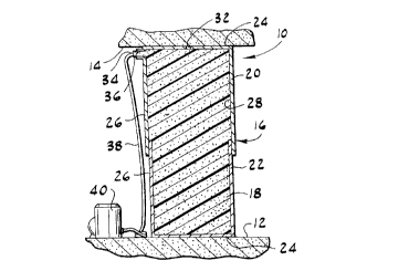
Fig. l is an elevation of a mine roof support of
this invention in its collapsed position;
Fig. 2 is an elevation of the support of Fig. l in
its extended (roof-supporting) position; and
Fig. 3 is an enlarged cross-sectional view showing a
sealing configuration between telescoping containment
members of the support of Fig. l.
Corresponding reference numerals designate
corresponding parts throughout the several views of the
drawings.
Description of the Preferred Embodiment
Referring now to the drawings, and first to Fig. l,
there is generally indicated at l0 a mine roof support of
this invention. The support is adapted to extend
vertically in a mine passageway between a floor 12 and a
roof 14 of the passageway. The support is shown in a
fully collapsed position in Fig. l and in an extended,
roof-supporting position in Fig. 2. The support includes
a containment structure, generally designated 16, and a
yieldable filler material 18 introducible (e.g.,
pumpable) into the containment structure to form a column
of material extending vertically in the passageway. In
the event of a mine convergence the yieldable material 18
CA 022~786~ 1sss-12-os
W098/50683 PCT~S98/01128
yields while providing continued support. As described
below, the containment structure 16 is designed to yield
without damage to the containment structure.
In the particular embodiment shown in the drawings,
the containment structure comprises two telescoping
containment members 20, 22 freely telescopically movable
relative to one another, the upper telescoping member
being designated 20 and the lower telescoping member
being designated 22. The containment members 20, 22 have
a telescoping sliding fit with one another to permit
adjustable extension of the support according to the
height of the passageway and to allow for movement of the
members as the mine roof 14 settles over time. The upper
and lower containment members 20, 22 have end walls 24
and cylindrical side walls 25 which combine to form a
cavity 28 for receiving the filler material. As
illustrated in Figs. 1-3, the lower containment member 22
has a diameter slightly smaller than the upper
containment member 20 for sliding of the lower
containment member within the upper containment member,
but it is to be understood that the containment structure
could also be configured such that the lower containment
member has a diameter larger than the upper containment
member. The cross sectional shape of the containment
members could also be other than circular (e.g.,
rectangular).
The containment members 20, 22 are sized to have as
small a diameter as possible to reduce manufacturing,
transportation and installation costs and to minimize
blockage of the mine passageway, while still providing
sufficient strength to support the anticipated load of
the roof without buckling or failure due to stress. The
specific size requirements are determined by the strength
of the filler material, the load to be imposed on the
support, the height of the support, and other mechanical
and structural considerations known to those skilled in
CA 022~786~ l998-l2-09
W098/50683 PCT~S98/01128
this field. The overall diameter of the support
preferably ranges from about 6 in. to about 8 feet. Even
more preferably, the outer diameter of the upper
containment member 20 is between 2.5 feet and 3.5 feet
and may be 3 feet - 0.125 inches, for example. The
diameter of the lower containment member 22 iS preferably
between 2.4 feet and 3.4 feet and may be 2 feet - ll.875
inches, for example. The clearance between the side
walls 26 of the upper and lower containment members is
preferably between 0. 0625 and 0. 25 inches, but this
number may vary. The thickness of the walls 26 of the
containment members may be, for example, 0.070 to 0.087
inches and are preferably sized to sustain at least 150
psi of pressure. The height of the side walls 26 of the
containment members 20, 22 may vary depending on the
height of the mine roof 14 to be supported. The
containment members 20, 22 are sized to allow for some
overlap of the side walls 26 of each contA;nment member
when the cont~;nme~t structure 16 iS in its extended
(roof-supporting) position. The containment members 20,
22 may be formed from 20 gage galvanized steel or any
other suitable material such as a polymeric material. It
is to be understood that the number of containment
members 20, 22, the diameters of the containment members,
the wall thickness of the members and the clearances
between the members may vary without departing from the
scope of this invention. The side walls of the
cont~;nme~t member9 may also be fabricated as single-
thickness walls or formed from multiple layers of
material. Alternatively, for added strength, the support
may comprise an inner set of telescoping containment
members inside an outer set of telescoping members.
Referring to Fig. 3, an annular seal 30 is provided
between the overlapping side walls to prevent leakage of
filler material 18 from between the sliding interface of
the cont~;nmPnt members 20, 22. The seal 30 could be on
CA 022~786~ lggs-l2-os
W098/S0683 PCT~S98/01128
either containment member, but it is shown in Fig. 3 as
being located around the circumference of the upper end
of the lower cont~;nment member 22 and sealing against
the inside wall of the upper containment member 20.
Sealing rings of various cross sectional shapes may be
used to obtain adequate sealing between the containment
members 20, 22. It is also possible to reduce the
clearances between the side walls 26 of the contA;nm~nt
members 20, 22 to eliminate the need for a seal 30. The
viscosity of the filler material 18 allows for
elimination of the seal 30 at the interface of the
containment members 20, 22 without excessive leakage of
the filler material 18 prior to the material hardening.
The end wall 24 of the upper containment member 20
has an opening 32 for venting air from the cavity 28
during filling of the structure with filler material 18.
The vent 32 allows air within the containment structure
16 to be forced out of the structure as the filler
material 18 is pumped into the structure to allow the
entire cavity 28 to be filled with the filler material.
Once the filler material 18 reaches the vent 32 and the
air has been forced out of the containment structure 16,
the vent will be occluded with filler material which will
eventually harden.
The upper containment member 20 further includes an
inlet port 34 for filling the cont~;nmPnt structure 16
with the filler material 18. The inlet port 34 is sized
to allow adequate flow into the cont~;nm~nt structure 16
to allow for quick installation of the support 10. The
port 34 may include a quick disconnect fitting 36 for
connecting a hose 38 to the inlet port. The inlet port
is preferably located on the side wall 26 of the upper
containment member 20 adjacent to the end wall 24 of the
member. The height of the lower cont~;nm~nt member 22 is
slightly less than the height of the upper containment
member 20 to prevent blockage of the inlet port 34 when
CA 022~786~ lggs-l2-os
W098/50683 PCT~S98/01128
the containment structure is in its fully collapsed
position.
The filler material 18 is preferably (but not
necessarily) a foamed cement material which is generally
made from cement entrained with air or other gas. The
material 18 is pumpable into the cavity of the
containment structure and hardenable after a relatively
short period of time. Alternatively, the filler material
could be a spongy liquid. When hardened the material
forms a very weak porous concrete entrained with air
having a compressive strength preferably in the range of
approximately lO0 psi to 400 psi, although this number
can vary considerably. The foamed cement material 18 may
be of the type available from ~lminco of Lexington,
Kentucky, sold under the trade name FOAMED CEMENT, or
from Fosroc/Celtite, Inc. of Georgetown, Kentucky, sold
under the trade name TECHSEAL. It is to be understood
that other suitable hardenable, yieldable materials may
be used as long as the material has suitable compression
and strength characteristics to support the weight of a
mine roof 14 and yet still yield to allow for movement of
the roof over time. The yield rate of the material 18
selected is based on the strength of the material of the
containment members 20, 22 and diameter of the
containment members. The selection of material 18 for
proper yield rate is important because if the material
yields too easily the support will not adequately support
the roof and if the material is too stiff, the support
may fail from excessive internal stress or overload the
mine roof 14 or floor 12.
Filler material 18 is pumped into the cavity 28 of
the containment structure 16 by means of a pump 40
(sometimes referred to as a "concrete" or "grout" pump)
connected to the inlet port 34 via a hose 38. The length
of hose 38 required varies depending on the type of pump
40 used and the specific material used. (Suitable pumps
CA 022~786~ Isss-l2-os
W098/50683 PCT~S98/01128
and associated equipment are typically provided by the
suppliers of the filler material used.) Additional
length of hosing 38 may be required to allow the foamed
cement to absorb the proper amount of air and develop the
correct consistency. The operating pressure and flow
rate of the pump 40 is determined by the volumetric
coefficient of the pump and the frictional losses in the
hose 38. A pressure as low as 1 psi may be sufficient to
force the cylinder to extend. However, it is preferable
to use higher pressures (e.g., 100-150 psi) to force a
sagging mine roof 14 up against more solid strata located
above the lower surface to prevent additional
disintegration of the roof.
A method for installing the roof support 10 in the
mine passageway includes the steps of pumping a fluid,
hardenable material 18 of the type described above, into
the telescoping containment members to cause the upper
containment member 20 to telescopically rise with respect
to the lower cont~lnm~nt member 22, venting air from the
containment structure 16 while pumping the material into
the structure, allowing the hardenable material to form a
yieldable set inside the containment structure, and
leaving the telescoping containment structure with the
hardened material therein permanently in place while
allowing for freedom of movement between the telescoping
parts of the containment structure so that in the event
of a mine convergence the yieldable material yields while
providing continued support and the telescoping
containment memberQ of the containment structure move
freely relative to one another to permit such yielding
without damage to the containment structure.
To use the mine roof support 10 in accordance with
the method of this invention, the containment structure
16 is placed on the floor 12 of the mine in its collapsed
position. The hose 38 is connected to the inlet port 34
and the filler material 18 is pumped into the cavity 28
.. ... .
CA 022~786~ lsss-l2-os
W098/50683 PCT~S98/01128
of the containment structure 16. As the filler material
18 is pumped into the cont~;nment structure 16, air is
vented from the containment structure 16 through the vent
32 and the upper containment member 20 telescopically
rises with respect to the lower containment member until
the end wall 24 of the member engages the roof 14 of the
mine. The pump 40 may force additional filler material
18 into the containment structure 16 after engagement of
the upper containment member 20 with the mine roof 14 to
ensure that there is sufficient contact between the upper
containment member and the roof to provide adequate
support of the roof. After the filling of the
containment structure 16 is complete, the hose 38 is
removed from the inlet port 34 and the filler material 18
is left to fully harden. The support 10 is then left in
place for as long as the mine is kept open or as long as
required. The design of the structure allows for freedom
of movement between the telescoping parts 20, 22 so that
in the event of a mine convergence the yieldable material
yields while providing continued support and the
telescoping containment members move freely relative to
one another to permit such yielding without damage to the
containment structure. The finished support 10 provides
a large load carrying capacity while maintaining a
yieldability sufficient to provide continuing support of
the mine roof 14 even after yielding a substantial
portion of its initial height to reduce the risk of a
catastrophic failure. The steel containment members also
prevent columnar shear failure of the support.
In view of the above, it will be seen that the
several objects of the invention are achieved and other
advantageous results attained.
As various changes could be made in the above
methods and constructions without departing from the
scope of the invention, it is intended that all matter
contained in the above description or shown in the
CA 02257865 lsss-l2-os
W098/50683 PCT~S98/01128
accompanying drawings shall be interpreted as
illustrative and not in a limiting sense.