Language selection

Search

Patent 2257988 Summary

Third-party information liability

Some of the information on this Web page has been provided by external sources. The Government of Canada is not responsible for the accuracy, reliability or currency of the information supplied by external sources. Users wishing to rely upon this information should consult directly with the source of the information. Content provided by external sources is not subject to official languages, privacy and accessibility requirements.

Claims and Abstract availability

Any discrepancies in the text and image of the Claims and Abstract are due to differing posting times. Text of the Claims and Abstract are posted:

  • At the time the application is open to public inspection;
  • At the time of issue of the patent (grant).
(12) Patent: (11) CA 2257988
(54) English Title: CONNECTOR BUSHING
(54) French Title: DOUILLE CONNECTRICE
Status: Deemed expired
Bibliographic Data
(51) International Patent Classification (IPC):
  • H01R 13/115 (2006.01)
  • H01R 13/11 (2006.01)
  • H01R 13/18 (2006.01)
  • H01R 4/18 (2006.01)
(72) Inventors :
  • NOTTROTT, RUDOLF (Germany)
  • MOSER, HANS (Germany)
  • LEHNER, ANTON (Germany)
(73) Owners :
  • FCI (France)
(71) Applicants :
  • F.C.I. - FRAMATOME CONNECTORS INTERNATIONAL (France)
(74) Agent: BKP GP
(74) Associate agent:
(45) Issued: 2003-09-02
(86) PCT Filing Date: 1997-06-16
(87) Open to Public Inspection: 1997-12-24
Examination requested: 2000-05-03
Availability of licence: N/A
(25) Language of filing: English

Patent Cooperation Treaty (PCT): Yes
(86) PCT Filing Number: PCT/EP1997/003117
(87) International Publication Number: WO1997/049145
(85) National Entry: 1998-12-11

(30) Application Priority Data:
Application No. Country/Territory Date
196 24 086.7 Germany 1996-06-17
196 24 088.3 Germany 1996-06-17

Abstracts

English Abstract


A plug connector sleeve (1) with a plug region (2) and a conductor connection
region (3), in which the plug region takes the form of a sleeve (4) with a
base (5), two side walls (7a, 7b) which are bent up from the base (5) and has
two cover halves (8a, 8b) running from the side walls and have free ends (9a,
9b) which are bent around towards the inside of the sleeve. The plug connector
sleeve (1) has a central base region (30) which follows the plug region (2),
is box-shaped with a base section, in the extension of the base of the plug
region with side walls in the extension of the side walls of the plug region
and with a cover section formed by third and fourth cover halves (18, 19)
which are formed by bending the side walls of the central base region.


French Abstract

L'invention concerne une douille de connecteur à fiches (1) comportant une zone d'enfichage (2) et une zone de connexion de conducteurs (3), la zone d'enfichage se présentant sous forme de douille (4) avec un fond (5), deux parois latérales (7a, 7b) cintrées vers le haut depuis le fond (5) et comportant une première et une seconde moitié de couverture (8a, 8b) qui partent des parois latérales et présentent des extrémités libres (9a, 9b) recourbées vers l'intérieur de la douille. La douille de connecteur à fiches (1) comporte une zone de base (30) médiane qui suit la zone d'enfichage (2), se présente sous forme de boîte, avec une partie de base, dans le prolongement du fond de la zone d'enfichage et avec une partie de couverture formée par une troisième et une quatrième moitié de couverture (18, 19), obtenues par cintrage des parois latérales de la zone de base médiane.

Claims

Note: Claims are shown in the official language in which they were submitted.
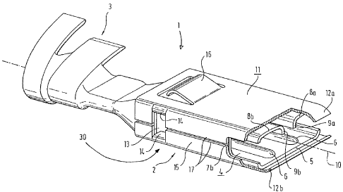

-7-
CLAIMS

1. A connector bushing (1) comprising a plug-in zone
(2) and a cable connection zone (3), the plug-in zone
(2) being formed as a bushing (4) with a base (5), two
side walls (7a, 7b) bent from the base (5), and first
and second roof halves (8a, 8b) which start from the
side walls and have free ends (9a, 9b) which are bent
over towards the interior of the bushing,
characterised in that
the connector bushing (1) comprises a central base zone
(30) following the plug-in zone (2), being formed in
the shape of a box with a base part in extension of the
base of the plug-in zone with side walls in extension
of the side walls of the plug-in zone and with a roof
zone which is formed by third and fourth roof halves
(18, 19) which are formed by bending over the side
walls of the central base zone.

2. A connector bushing according to claim 1,
characterised in that the third roof half has an extension
(19a) which serves as abutment for the fourth roof
half.

3. A connector bushing according to claim 1 or 2,
characterised in that the cable connection zone (3) is
connected to the central base zone (30) via a flattened
U-shaped zone (20) which has side walls each of which

-8-

starts from the base of the central zone and the roof
of the central base zone.

4. A connector bushing according to one of the preceding
claims, characterised in that the plug-in zone and
the central base zone are embraced by a cage (11) which
encloses the plug-in zone in the shape of a box in
order to prevent the side walls (7a, 7b) from opening
towards the outside and in order to restrict the opening
of the first and second roof halves (8a, 8b).

5. A connector bushing according to claim 4, characterised
in that the cage has side walls (15) which have
inwardly bent tags (14) which mesh with openings (13)
which are formed in the side walls of the central base
zone.

6. A connector bushing according to claim 5, characterised
in that the cage consists of a folded metal
sheet and the edges (17) of the folded metal sheet abut
on one side wall (7b) of the plug-in zone.

7. A connector bushing according to claim 6, characterised
in that the cage (11) has spring tongues (12a,
12b) which are bent inwardly at the front side of the
base and of the roof of the plug-in zone.

8. A connector bushing according to one of the preceding
claims, characterised in that the base of the plug-in
zone has at least one rib extending in parallel to
the plug-in direction, which projects into the interior
of the bushing.

Description

Note: Descriptions are shown in the official language in which they were submitted.


CA 022~7988 l998-l2-ll


Connector bushing


This invention relates to a connector bushing according
to the preamble of claim 1. Such a connector bushing
has been known from EP 573 825 Al and FR-l 560 917 Al
as well as from DE-OS 1 904 354 and DE-4 314 363 C2.
Connector bushings of this kind are used particularly
where high contact pressure between the bushing parts
and the pin introduced therein is important. Such con-
nectors have also proved satisfactory in applications
in which the connection is subject to considerable vi-
bration.

Although conventional connector bushings of this kind
already ensure high contact pressures on the introduced
pin, this does not automatically result in good elec-
trical contact, particularly if there has been slight
tilting on introduction of the pin, in cases where such
tilting cannot be automatically corrected. The result-


866-50.429/430 P-CM/m~c

CA 022~7988 1998-12-11


- 2 -


ing transition resistance and any local overheating and
subsequent risk of oxidation impair the conductivity of
this connection.

German utility model 8 811 020 describes a surmounting
spring for preventing the connector bushing from
spreading apart.

This invention is based on the problem of improving a
connector bushing of the type referred to in such man-
ner as to ensure high contact pressure on the pin while
ensuring high conductivity of the connection.

This problem is solved in accordance with the claim.
The subclaims indicated preferred embodiments of the
present invention.

The steps according to the invention, particularly the
provision of ribs on the base of the bushing, in order
reliably to ensure adequate contact surfaces for the
contact and prevent deformation of the bushing by sur-
rounding the same in a rigid cage, decisively improve
the contact pressure and electrical conductivity of the
pin bushing according to the invention.

One exemplified embodiment of a pin bushing according
to the invention will be explained hereinafter with
reference to the drawing wherein:

Fig. 1 shows a pin bushing according to the invention
in perspective.

CA 022~7988 1998-12-11


Fig. 2 is a partial section and plan view along the
longitudinal centre-line in the region of the bushing.

Fig. 3 shows the connector bushing of Fig. 1 seen from
below and above.

Fig. 4 shows the connector of Fig. 1 with the box-
shaped surmounting spring, and

Fig. 5 shows the surmounting spring of Fig. 4 in side
view and plan view.

The connector 1 shown in Fig. 1 comprises a plug-in
zone 2, a base zone 30 and a cable connection zone 3.
The plug-in zone 2 is formed as a bushing having a base
5 in which two ribs 6 are stamped, which project to-
wards the interiour of the bushing and each extend par-
allel to the longitudinal centre-line 10 of the connec-
tor. Side walls 7a, 7b are bent over at 90~ at the two
longitudinal edges of the base and adjoining the top
edge of each is a roof half 8a, 8b, the front edges of
which are again bent over towards the interior of the
bushing, the front edges extending parallel to one an-
other and parallel to the surface of the base.

The cable connection zone is formed as a crimp connec-
tion here, but this is only one of numerous possibili-
ties depending on the problem involved.

An opening 13 is visible in the side wall 7b in the
rear zone of the bushing and there is a corresponding
opening on the opposite side 7a. The side walls 7a and

CA 022~7988 1998-12-11


7b also recede somewhat relatively to the base 5 and
the roof 8a, 8b in the front plug-in zone. The cable
connection zone has a U-shaped cross-section, the base
side extending parallel to the side wall 7b of the
bushing part. The side wall of the base zone 30 also
extends in extension of the side wall 7b and the base
part of the cable connection zone 3.

As will be seen particularly from Fig. 3, the above-
mentioned side walls, which are each in alignment with
one another, thus form the "spine" of the connector ac-
cording to the invention.

Fig. 2 is a partial section of the bushing zone and the
crimp tags of the cable connection zone 3. The ribs 6
are stamped with a relatively considerable bend radius
parallel to one another and parallel to the longitudi-
nal centre-line of the connector in the base 5 of the
bushing zone. The distance between them is greater than
the distance between the end edges 9a, 9b of the roof
halves 8a, 8b. This configuration ensures that the pin
to be introduced has a large contact surface on the
back of the ribs 6 and the front edges 9a, 9b of the
roof halves 8a, 8b. In particular, this prevents an
edge of the pin tilting obliquely in the region of the
curve between the base 5 and the side wall 7a, 7b so
that the contact is restricted to the burr at the
stamped edges of the pin between the latter and the
bushing.

The front edges of the roof halves 8a, 8b are pressed
on to the pin with a certain resilient force, practi-


CA 022~7988 1998-12-11


cally the entire zone, side walls and roof being opera-
tive as spring arms.

To prevent excessive deformation of the bushing and in-
crease the rigidity of the fit of the pin in the bush-
ing, the latter is surrounded by a surmounting spring
11 as shown in Fig. 4. The latter may be made from a
hard elastic material, e.g. steel. It has the shape of
a box and inwardly bent spring strips which are rounded
in the end zone. These spring strips 12a, 12b protect
the pin from contact with the front edges of the ribs
and the axial bends.

Inwardly bent lugs of the side walls of the surmounting
spring 11 engage in the windows 13, which are formed in
the rear end of the bushing zone of the connector, in
order to fix the spring on the connector. The spring
has recesses in the side walls just like the side walls
7a and 7b in the region of the front opening of the
bushing. This provides a means of observing the intro-
duction process and allows a certain elasticity of the
base and roof zones of the bushing in the event of a
pin being inserted with slight tilting. Locking arms
are also formed in the rear zone of the spring in the
roof zone and, if required, in the bottom zone, the
free ends of the locking arms being bent obliquely
rearwards towards the bushing in order to ensure re-
leasable locking in a plug casing. The spring 11 is of
substantially box shape and the edges 17 of the bent-
over metal sheet abut one another in parallel relation-
ship in the middle of a side wall 7b.

CA 022~7988 1998-12-11


The connector bushing according to the invention is ex-
tremely compact and has amazingly high rigidity as a
result of a number of steps. On the one hand, the
shifting of the base side from which the adjoining
walls are bent is prevented towards one side so that
the opening of the bushing, possibly after the side
walls have yielded to the introduction of a pin, can
continue into the middle zone of the base and then on
into the cable connection zone, so that increased ri-
gidity is obtained for this reason alone. The box-
shaped cage formed by the spring 11 in turn has its
side which is weaker to deformation situated where the
backbone of the connector is situated, so that here
again a rigid and effective support is ensured.

The above description of one exemplified embodiment has
no limiting force but serves solely to explain the pre-
sent invention.

Representative Drawing
A single figure which represents the drawing illustrating the invention.
Administrative Status

For a clearer understanding of the status of the application/patent presented on this page, the site Disclaimer , as well as the definitions for Patent , Administrative Status , Maintenance Fee  and Payment History  should be consulted.

Administrative Status

Title Date
Forecasted Issue Date 2003-09-02
(86) PCT Filing Date 1997-06-16
(87) PCT Publication Date 1997-12-24
(85) National Entry 1998-12-11
Examination Requested 2000-05-03
(45) Issued 2003-09-02
Deemed Expired 2007-06-18

Abandonment History

There is no abandonment history.

Payment History

Fee Type Anniversary Year Due Date Amount Paid Paid Date
Application Fee $300.00 1998-12-11
Registration of a document - section 124 $100.00 1999-02-22
Maintenance Fee - Application - New Act 2 1999-06-16 $100.00 1999-04-26
Request for Examination $400.00 2000-05-03
Maintenance Fee - Application - New Act 3 2000-06-16 $100.00 2000-05-03
Maintenance Fee - Application - New Act 4 2001-06-18 $100.00 2001-05-18
Maintenance Fee - Application - New Act 5 2002-06-17 $150.00 2002-06-05
Maintenance Fee - Application - New Act 6 2003-06-16 $150.00 2003-05-13
Registration of a document - section 124 $100.00 2003-06-02
Section 8 Correction $200.00 2003-06-02
Final Fee $300.00 2003-06-09
Maintenance Fee - Patent - New Act 7 2004-06-16 $200.00 2004-06-09
Maintenance Fee - Patent - New Act 8 2005-06-16 $200.00 2005-05-27
Owners on Record

Note: Records showing the ownership history in alphabetical order.

Current Owners on Record
FCI
Past Owners on Record
F.C.I. - FRAMATOME CONNECTORS INTERNATIONAL
LEHNER, ANTON
MOSER, HANS
NOTTROTT, RUDOLF
Past Owners that do not appear in the "Owners on Record" listing will appear in other documentation within the application.
Documents

To view selected files, please enter reCAPTCHA code :


To view images, click a link in the Document Description column. To download the documents, select one or more checkboxes in the first column and then click the "Download Selected in PDF format (Zip Archive)" or the "Download Selected as Single PDF" button.

List of published and non-published patent-specific documents on the CPD .

If you have any difficulty accessing content, you can call the Client Service Centre at 1-866-997-1936 or send them an e-mail at CIPO Client Service Centre.


Document
Description 
Date
(yyyy-mm-dd) 
Number of pages   Size of Image (KB) 
Representative Drawing 1999-03-01 1 13
Cover Page 1999-03-01 1 57
Drawings 1998-12-11 4 67
Claims 1998-12-11 2 65
Description 1998-12-11 6 188
Abstract 1998-12-11 1 55
Cover Page 2003-07-14 1 49
Representative Drawing 2003-07-14 1 15
Cover Page 2003-07-16 2 96
Cover Page 2003-07-29 1 48
Prosecution-Amendment 1999-02-22 1 38
Assignment 1999-02-22 2 68
Correspondence 1999-02-16 1 32
PCT 1998-12-11 12 362
Assignment 1998-12-11 4 119
Fees 1999-04-26 1 44
Fees 2000-05-03 1 40
Prosecution-Amendment 2000-05-03 1 23
Prosecution-Amendment 2000-08-03 3 96
Fees 2001-05-18 1 39
Fees 2002-06-05 1 39
Correspondence 2002-11-25 8 209
Correspondence 2002-12-12 1 14
Correspondence 2002-12-12 1 19
Fees 2003-05-13 1 32
Correspondence 2003-06-09 1 32
Correspondence 2003-06-02 16 894
Prosecution-Amendment 2003-07-16 2 54
Fees 2004-06-09 1 27
Fees 2005-05-27 1 28