Note: Descriptions are shown in the official language in which they were submitted.
~ ~ \ CA 022~8096 1998-12-08
t_ ~.,
TOOTHBRUSH WITH A REPLACEABLE 8RUSH PART
The invention relates to a toothbrush with a handle, a head constructed as a
casing open on at least one side, a brush part insertable in said open side
and having a support and a bristle facing and with locking means within the
casing and on the support for fixing the brush part, the casing having a side
plate or cheek supporting the support in the vicinity of its periphery and on
the head means for the toolless pressing out of the brush part from the back
of the head.
Brushes are known (US 403 350, US 1 148 566, US 1 711 621, US 2 326 632), in
which the brush part having the bristle facing is subsequently inserted in
the actual brush body. This frequently takes place for manufacturing reasons
and particularly if it is impossible to directly connect the bristle bundles
to the brush body, e.g. by thermal processes, such as welding, moulding in,
etc. Constructions are also known in which the brush part is detached from
the brush body and can be replaced by another brush part (GB 1932/19lO). The
known constructions are not or are only inadequately suitable for tooth-
brushes.
Toothbrushes are required much more frequently than other types of brushes.
The reason is the frequent use necessary for correct oral hygiene (up to
three times daily) and the rapid wear resulting from this. In addition,
even in the case of relatively limited wear which would be acceptable with
other brushes, a toothbrush has to be replaced, so as to always ensure an
optimum effectiveness.
Due to the high toothbrush consumption, approximately 150 million per annum
in Germany, there is an increasing problem of disposal and protecting
resources, because the material fraction rendered unusable due to wear is
extremely small compared with the total material and the total material to be
disposed of, even in the case of a 100% recycling, cannot be processed to the
same product, because the recycled material no longer fulfils the high
quality requirements, which are vital e.g. for the bristle material of a
toothbrush. Even if the known brushes with a replaceable brush part would
fundamentally make it possible to only replace the brush part after wear,
this problem has not hitherto been in the foreground and also in the case of
standard brushes, such as cleaning brushes, body brushes, cosmetic brushes,
CA 022~8096 1998-12-08
etc. it is relatively unimportant, because the use period is much longer and
the material ratio of unusable and still usable material is not in the same
disproportion as with toothbrushes.
Finally, in connection with toothbrushes account must be taken of the special
feature that they must be correctly usable by humans of all age classes and
all education levels, so that the replacement of the brush part must be
possible in a very simple manner and with limited force expenditure, whilst
at the same time adequately securely joining the parts.
At present there are essentially two systems on the market. In the case of
so-called replacement head brushes (EP O 199 849 B1, DE 94 20 405 U1) the
entire head with the bristles is detachably fixed to the handle. The locking
fixing means are located on the handle substantially transversely to its
longitudinal axis and on a shoulder of the head and are brought into engage-
ment by the assembly of the head and handle in the longitudinal axial direc-
tion. Conversely the two parts can be detached by pulling apart in the
longitudinal axial direction. These replacement head brushes are satisfac-
tory from the use and hygienic standpolnts. However, the plastics fraction
of the head, which becomes waste when the bristles become worn, is still con-
siderable. The further disadvantage arises that the fixing means are located
in the transition area between head and handle, i.e. in an area where the
greatest bending forces act during use. However, it is preclsely in this
area that the toothbrush is weakened by the constructional measures for the
fixing means. This is particularly serious because, for use reasons, between
the handle and the head it is desirable to have a slender and optionally
resilient neck, which cannot be implemented with such replacement head
brushes. Therefore replacement head brushes have already been proposed, in
which the head is locked with the slender neck on the thicker handle. Thus,
although the use advantage is substantially maintained, this is achieved at
the cost of a larger amount of plastics waste. In addition, the risk also
arises with all replacement head brushes, that in the case of incorrect
locking or a failure of the locking system during use, serious injury can
occur in the oral cavity.
With other known systems, to which belongs the toothbrush according to the
CA 022~8096 1998-12-08
. .
-- 3
preamble of claim 1, the bristles are fixed to a support in the form of a
thin plate and said brush part is replaceably locked in the frame or casing-
like head (DE 30 38 895, 37 24 640). The support is provided on its circum-
ferential surface with ledge-like catches and the casing has corresponding
channel-like depressions. On its back the support also has a pin, which
engages in a hole in the bottom of the casing and forms on the back of the
head an exposed pressure surface. The support is locked in the head and can
be ejected by pressure on the pin. The plastics fraction to be replaced in
the case of bristle wear is reduced to a minimum and the replaceable brush
parts can be inexpensively manufactured due to the small amount of material
used. However, hygienic and constructional problems arise as compared with
replacement head brushes. In the gap necessarily present between the support
and the casing cheek, which only dries inadequately, there is a deposition
of dirt and accumulation of bacteria. This applies to a greater or lesser
extent for the entire gap between head and support.
Thus, on its bristle side, the support is provided with an elastic, circum-
ferential border (DE 37 24 640 C2), whose back sealingly engages against
the front face of the casing cheek. This presupposes corresponding tensile
forces drawing the support into the casing and consequently correspondingly
high locking forces. In turn these make more difficult the insertion and
ejection of the brush part. As locking takes place by self-closure, the
locking means must be of a correspondingly large-volume nature, which
requires considerable wall thicknesses on the head. Even more complicated is
a construction (DE 296 00 398 U1), in which on all the sealing faces between
the support and casing are provided elastic flat seals, which by a corres-
pondingly high pretension simultaneously retain the brush part. The pre-
tension must be completely absorbed by the casing cheek, which necessarily
widens after a short time and a reliable hold of the brush part is no longer
ensured.
Other proposals (DE 91 O9 625 U1, DE 44 34 617 A1), which provide locking
ledges in portionwise manner on the support circumference, lead to a corres-
ponding reduction of the sealing of the gap, because the locking ledges and
recesses are located in the sealing surfaces and very narrow tolerances must
be respected, in order on the one hand to ensure a snug engagement of the
CA 022~8096 1998-12-08
sealing surfaces and on the other a reliable locking. It is scarcely poss-
ible to achieve such tolerances with injection moulded parts and the inexpen-
sive plastics required for the head and handle. In addition, the casing
cheek is constantly under elastic pretension due to the locking forces.
Since plastics are not creep-resistant under tension (cold flow), there is a
very rapid decrease to the tensional force of the casing cheek, so that the
gap between cheek and support enlarges and the infiltration of dirt and
bacteria is aided. As plastic fatigue and the resulting increase in the
tolerances can scarcely be noticed by the user, he may only notice the
failure of the locking means when cleaning the teeth. If the brush part is
detached during use, it can once again lead to injury to the oral cavity and
gingiva.
A very stable and durable connection of the brush part and head is brought
in a known toothbrush (DE 41 04 314 A1) in that on the back of the support
are shaped two mutually V-shaped ledges, which pass over the entire support
length. They engage in a slot on the head opening outwards in V-shaped man-
ner and which also passes over the entire length in its longitudinal axis.
During insertion the ledges must be deformed inwards and towards one another
to such an extent that they can pass through the narrowest cross-section of
the V-shaped slot and then expand in said slot. Thus, the elastically
deformed parts of the locking connection are located on the replacement part,
where material fatigue is less important. The deformation forces on the
ledges required for producing and detaching the locking connection are so
high that the brush part can only be pressed or levered out with the aid of
specially adapted tools. The need for such special tools not only leads to
correspondingly high system costs for the consumer, but is prejudicial to a
practical acceptance of the system by the market. This also applies because
it is not possible to fulfil a requirement for avoiding injury, namely a
smooth shape of the brush back. In addition, this toothbrush is also com-
pletely unacceptable for hygienic reasons, because the slot and ledges form
several cracks, in which can be deposited dirt, toothpaste residues and
bacteria.
The latter disadvantage is somewhat reduced in another known construction
(US 4 543 679), in that in place of the ledges an expanding pin is provided,
CA 022~8096 1998-12-08
which engages in an outwardly conically widening hole on the casing bottom.
The problem of the invention is to so construct a toothbrush of the afore-
mentioned type, that the speclal hygienic requirements are fulfilled and the
use characteristics improved.
According to the invention this problem is solved in that the mutually
engaging surfaces on the cheek of the casing and on the periphery of the
support are constructed as completely smooth-walled sealing surfaces and the
locking means have resilient detents inwardly displaced with respect to the
sealing surfaces and which are located in a space between the casing bottom
and the support back facing it.
An important advantage of the invention is that the functions "sealing" and
"locking" are constructionally separated. The smooth periphery on the
support and the smooth contact surface of the cheek constitute the pre-
requisite for a completely satisfactory, sealing engagement with one another
of said surfaces. This can be assisted by a slightly conical construction of
these surfaces. As a result of the construction of the locking means as
resilient detents outside the sealing surfaces the casing cheek is not placed
under pretension by locking and retaining forces and consequently cold flow
cannot occur there, so that it can fulfil its sealing function for a long
time. Cavities, gaps, etc. are avoided to such an extent that, in the
desired manner, after use the toothbrush rapidly dries and consequently the
accumulation of bacteria is prevented, whilst the deposition or infiltration
of toothpaste residues, etc. are avoided. The resilient detents ensure a
functionally reliable locking, but still permit an easier replacement.
As the locking means are exclusively located in the interior of the casing
between its bottom and the back of the support, the outer contour of the
toothbrush in the vicinity of the head can be adapted in optimum manner to
the intended correct use, e.g. rounded, smooth contours are ensured, so that
during oral hygiene oral cavity injuries are avoided, whilst the resilient
detents are positioned in an area where their dimensioning is not constricted
by other constructional circumstances. They can therefore be so designed
that their operational reliability is maintalned over a long period. The
CA 022~8096 1998-12-08
entire, thin-walled casing cheek is kept free from tension. The positioning
of the locking means on the one hand and the pressure surface for detachment
on the other ensure that the bristle part is not detached in an untimely
manner, because the pressure acting on the bristles during use cannot lead to
a release of the locking system and instead for this purpose it is necessary
to have a planned, but limited pressure on the back of the head. The easy
replaceability of the brush part encourages the use of this system by the
user, particularly as the possibility exists of using brush parts with
bristles having different hardness characteristics and positioning.
In a preferred construction the resilient detents are shaped in inwardly
projecting manner on the casing bottom and cooperate with depressions on the
support back.
An advantageous embodiment is characterized in that on the casing bottom
forming the back of the brush head there is a through opening, whose wall is
at least partly inwardly lengthened towards the resilient detents and that
the support has a pin engaging in said through opening whose front face forms
an exposed pressure surface for pressing out the brush part or cooperates
with a pressure surface on the casing.
In this embodiment the through opening with its sleeve-like wall fulfils
several functions. It can firstly guide the pin on the support and secondly
at least part of its wall serves to construct the resilient detents, i.e. for
positioning and fixing the support. Finally, the through opening provides
the possibility of constructing the pressure surface on the back of the head.
It is either formed directly by the pin passing through the through opening,
namely by its exposed front face, or it is constructed as a casing part
closing said through opening on the back of the head and the pressure applied
to the pressure surface acts on the pin via the casing.
If the pin is guided on the wall of the through opening, it is provided on
its circumference with the depressions in which spring from the outside the
detents on the casing.
If the exposed front face of the pin forms the pressure surface, it advantage-
CA 022~8096 1998-12-08
ously slightly pro;ects over the contour of the casing on the back of the
head, which indicates its function and the pressure for releasing the locking
system can be applied without difficulty.
Apart from the use advantages, the aforementioned embodiment has the advan-
tage that the toothbrush only comprises two components, namely the handle
with the head forming the casing and the brush part with the support and
bristles. Therefore the toothbrush can be easily and inexpensively manu-
factured.
An embodiment which is somewhat more complicated from the manufacturingstandpoint, but offers the same use advantages, is characterized in that the
pin is placed in the through opening spaced from its wall and the support has
depressions externally engaging over the resilient detents.
Preferably the through opening on the back of the head is closed by a pres-
sure plate forming the pressure surface and which internally engages on the
front face of the pin.
This construction has the advantage that the toothbrush head is completely
closed on the back, where there are consequently no sealing problems with all
their possible disadvantages.
In this embodiment the pressure plate forming the pressure surface can be
made from a rubber-like material, e.g. an elastomer and can be subsequently
inserted on the opening rim of the through opening and fixed e.g. by locking
on the wall of the opening or moulded onto the opening in an in-mould process.
The pressure plate is at least elastically deformable to such an extent that
when pressure is exerted on the pressure plate the distance necessary for
the release of the support is covered. Thus, the pressure is applied by the
pressure plate on the pin, so that the support is displaced in the pressure
direction and the detents are freed.
Instead of this the pressure plate can be in one piece with the head and can
either be connected by a correspondingly thin wall thickness of the head in
this area in resilient manner to the remaining casing, or this takes place by
~ CA 022~8096 1998-12-08
.~ .
means of a flexible wall portion.
If the pressure plate is a one-piece, but resilient part of the head, the
detents can be shaped laterally of the pressure plate on the casing bottom
and can be expanded from the locking position fixing the support between them
by pressure on the pressure plate and accompanied by the freeing of the sup-
port.
The spring characteristic of the detents can be obtained with virtually any
random plastics material by a certain length of the detents, whereas the
casing can be dimensionally stable. Spring characteristics can also be
achieved by thinner wall portions on the back of the head, so as to permit
the movement with a limited travel of the pressure plate forming part of the
casing. In addition, such flexible wall portions can be constructed in the
area of the start of the detents on the casing, so that pressure on the
pressure plate gives rise to their displacement, as well as an expansion of
the detents, so that the support comes free from the locking system and can
drop out downwards.
Externally the cheeks engage entirely or partially over the support, a com-
plete overengagement with a flush connection of the outer faces of the
support and cheek being advantageous in order to avoid corners, recesses,
etc.
Instead of this the support can also engage on the front face of the cheek
and be flush with its outside. This creates an additional sealing surface.
This construction also has no recesses or steps, which would aid dirt depo-
sition.
In another embodiment, the support has a circumferential border on the side
opposite to the bristle facing and with which it externally engages over the
cheek.
This embodiment has the advantage that the support forms a closed surface
not only in the area of the bristle facing, but also on the sides of the
head.
CA 022~8096 1998-12-08
It is mainly these areas which come into contact with the gingiva when the
toothbrush is in use, so that through the smooth surface in this area an
injury risk is prevented. In addition, the areas close to the bristle facing,
due to the toothpaste applied there, have a particular dirt deposition
tendency, whilst also allowing the accumulation of bacteria. Due to the
smooth, gap and recess-free construction of the support and its border
engaging over the cheeks such problems are avoided.
Both the aforementioned embodiments have the advantage that for a given con-
tour of the head, it is possible to provide a maximum number of bristles on
the support.
The inventive construction of the casing also offers the possibility of the
support being made from an elastomer and being sealed against the cheek,
which can be assisted by sealing lips. The inventive construction of the
casing ensures that the cheeks clamp and compress in frame-like manner the
elastomer support. Additional increased frictional forces occur in the area
of the sealing faces, which reliably avoids gaps. The ends of the bristles
located in the support are elastically supported.
Finally, the pressure surface can be optically differentiated from the remain-
ing casing by the surface design, so as in this way to indicate the function
of the pressure surface to the user. This optical differentiation can take
place by a corresponding profiling, different material, colouring, etc.
At least in the area of the cheek, the casing can externally have a soft
elastic covering in o~der to protect the mucosa. This can additionally
cover the front face of the cheek and with its inner edge sealingly engage on
the circumferential surface of the support.
Since in the case of the inventive construction the locking means are no
longer located on the casing cheek, but instead only fulfil guidance and
sealing functions, they can be thinner than in the known constructions.
Conversely the support surface and consequently the number of bristles or
bundles can be increased or enlarged.
CA 022~8096 1998-12-08
-- 10 --
The invention is described in greater detail hereinafter relative to non-
limitative embodiments and with respect to the attached drawings, wherein
show:
Fig. 1 A partial representation of a toothbrush in a plan view of the back.
Fig. 2 A section II-II of fig. 3.
Fig. 3 A plan view of the bristle facing.
Fig. 4 A section IV-IV of fig. 3.
Fig. S A longitudinal section through the toothbrush head in another
embodiment without the brush part.
Fig. 6 A bottom view of the head.
Fig. 7 A section corresponding to fig. 5 of another embodiment.
Fig. 8 A bottom view of the brush head according to fig. 7.
Fig. 9 A longitudinal section through the brush head in another
embodiment.
Fig. 10 A bottom view of the head according to fig. 9.
Fig. 11 A longitudinal section through the head in another construction.
Fig. 12 A bottom view of the head according to fig. 11.
Fig. 13 A longitudinal section through the brush head in a modified
construction.
Fig. 14 A bottom view of the head according to fig. 13.
CA 02258096 1998-12-08
r
~ 11 ~
Figs. 15 Cross-sections of the brush head according to fig. 4 with a
to 22 different construction of the casing and the brush part support.
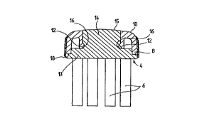
The toothbrush shown in figs. 1 to 3 comprises a broken away represented
elongated handle 1, a head 2 and a replaceable brush part 3, which has a
support 4 with the bristle facing 5 of individual bristle bundles 6. The
head Z of the toothbrush is constructed as a casing 7 in which is replaceably
inserted the brush part 3 with its support 4.
In all the embodiments the casing 7 has as a lateral boundary a circumfer-
ential side plate or cheek 8, which is closed by a wall 9 towards the handle
1 (figs. 2 and 4). With the wall 9 the circumferential cheek 8 forms a type
of dimensionally rigid frame, which together with the back 10 forms a down-
wardly open cavity for receiving the support 4.
In the embodiment according to figs. 1 to 4 the casing also has a through
opening 11, whose wall is at least partially formed by resilient detents 12
profecting into the cavity. The planar support 4 on the side of the bristle
facing S comprises a plate-like part 13, whose contour corresponds to the
contour formed on the inside of the cheek 8 and the wall 9, as well as a
pin 14, which passes through the through opening 11 and is additionally
guided therein. The pin 14 has an exposed front face projecting slightly
over the back 10 of the casing 7 and which forms a pressure surface 15. As
shown in fig. 1, this pressure surface can be optically differentiated,
optionally also surface-profiled.
With the resilient detents 12 in the area of the through opening 11 are
associated correspondingly shaped locking recesses 16 on the support 4,
which in the represented embodiment are located on the circumference of the
pin 14 in the area of the transition to the plate-like part 13 and inwardly
displaced with respect thereto.
From the use position shown in figs. 2 and 4 the brush part 3 can be easily
replaced by a new brush part, in that with the finger a pressure acting in
the direction of the bristle facing is exerted on the pressure surface 15
under which the resilient detents 12 retreat outwards, so that the brush part
CA 02258096 1998-12-08
- 12 -
3 drops downwards.
The bristles 6 of the brush part 3 can be fixed in numerous different ways
to the support 4, e.g. in preshaped holes, by anchoring means or adhesive,
but can also be welded to the support or, provided with thickened portions 17,
moulded into the same.
In the embodiment of figs. 5 and 6 the through opening 11 has an asymmetrical
oval shape and its wall in the cavity of the casing 7 is lengthened towards
the resilient detents 12, which form a circumferential ring. The embodiment
of figs. 7 and 8 differs from that of figs. 5 and 6 only in that the through
opening 11 and resilient detent 12 are circular.
In the embodiments according to figs. 9 to 14 the wall of the through opening
11 only partially projects into the cavity for forming the resilient detent
12. Thus, figs. 9 and 10 show a detent 12 having a U-shape, whereas in the
embodiment according to figs. 11 and 12 the through opening 11 on the facing
narrow sides forms two resilient detents 12 with an arcuate shape and in
figs. 13 and 14 the wall of the through opening on the longitudinal sides is
lengthened to the opposite detents 12.
Figs. 15 to 22 show different constructions of the casing, support and
locking means. In the embodiment of fig. 15 the support 4 once again has a
plate-like part 13 and a shoulder 14, as well as the head-forming casing,
much as in the embodiment of fig. 4. Differing from the latter embodiment,
the plate-like part 13 of the support 4 forms the lower termination of the
head and the cheek 8 with its front face 18 forms an abutment for the top of
the plate-like part 13 of the support 4. Otherwise the support 4 is termin-
ated in circumferentially flush manner with the outside of the cheek 8.
In the embodiment of fig. 16 the plate-like part 13 of the support 4 isinwardly offset in step-like manner on its top and engages with the step on
the front face 18 of the cheek 8. The plate-like part 13 is guided with the
drawn in part on the inside of the cheek 8. In this embodiment an elastomer
covering 28 is injected onto the outside of the cheek and protects the mucosa.
The covering 28 can project over the front face of the cheek 8 and sealingly
-
CA 022~8096 1998-12-08
- 13 -
engages on the circumference of the plate-like part 13.
Unlike in fig. 16, fig. 17 shows a support 4 with a plate-like part 13, which
is once again mounted and guided on a step 19 on the inside of the head cheek
8.
In the embodiment according to fig. 18 the support 14 has on its plate-like
part 13 an upwardly drawn border 20 in which engages on the inside with a
corresponding step the cheek 8. Another construction is shown in fig. 19,
where the cheek 8, without an external step, engages behind the raised edge
20 of the support 4.
In the embodiment according to fig. ZO the resilient detents 12 point
outwards and the support 4 is provided with upwardly projecting studs 21,
which form the locking recesses 16, over which externally engage the detents
12. The pin 14 passes through the through opening 11 with a greater spacing
from the wall in this embodiment. The through opening 11 is closed at the
top by a pressure plate 22 forming the pressure surface 14 and which at 23
is locked or moulded on the wall of the through opening 11. The pressure
plate 22 has a rubber-like construction. The underside of the pressure plate
22 engages on the front face of the pin 14. If pressure is exerted on the
pressure surface 22 the pin 14 is moved downwards. The rigid studs 21 on the
support move the resilient detents 12 inwards, which frees the support 4 with
the bristle bundles 6.
In the embodiment according to fig. 21 the support 4 once again has a plate-
like part 13 and a shorter pin 24 than in the preceding embodiments and which
on its circumference forms the locking recesses 16 for the resilient detents
12. In the centre the casing 7 has a pressure plate 25, which is connected
to the casing by means of thin-walled, resilient wall portions 26. Immedi-
ately following onto the wall portions 26 are shaped resilient detents, which
are once again connected by means of resilient wall portions 27 to the cheeks
8 of the casing 7. In the case of pressure on the pressure plate 25 the
detents 12 are expanded outwards (fig. 22) as a result of the elastic wall
portions 26 and 27, freeing the support 4 with the bristle bundles 6, so that
it drops downwards.
CA 022~8096 1998-12-08
t ~ .
As can be gathered from the drawings, in all the embodiments the engaging in-
side of the cheek 8 and the circumferential surface of the support 13 are
smooth and slightly inwardly conically tapered, whereas the locking means 12,
16 are inwardly displaced over the same.