Note: Descriptions are shown in the official language in which they were submitted.
CA 022~8296 l998-l2-l~
W098/OOOSl PCT~S97/07434
G~RMENT HANGER
The present invention relates generally to
molded plastic garment hangers as are widely used for
the purpose of shipping and displaying garments.
Garment hangers of that type may be simply constructed
as molded plastic structures incorporating a central
hook adapted to be suspended from a suitable support,
such as a garment display rack or the like. The
garment hanger body typically has arms extending in
opposite directions from the base of the central hook
so as to facilitate a garment to be suspended
therefrom. The opposite or distal ends of the arm
typically have garment clips formed thereon to enable
the attachment of various kinds of garments thereto,
such as underwear, slips, brassieres, swimwear,
multiple garments, and the like.
A wide variety of such garment hangers are
presently known. Typically, such garment hangers have
a hook portion elevated above a horizontally-extending
body portion, as shown in U.S. Patent No. Des.
246,817. In order to grasp a garment effectively,
clips, grips, slots or hooks (collectively referred to
herein as "clips") are placed at the ends of the body
portion of the hanger. Such prior art hangers are
exemplified by U.S. Patent Nos. 4,623,079; 4,629,102;
4,892,237; 5,065,916; and 5,129,557.
U.S. Patent Nos. 4,623,079 and 4,629,102
disclose a hanger having an elevated hook member, a
hanger body having horizontally extending arms and ,
respectively, resilient grips and clips of a U-shaped
3o
, . _
CA 022~8296 1998-12-l~
W098/0~51 PCT~S97/07434
configuration located at the end of each arm. The U-
1 shaped configuration includes first and second
members, which are also being connected to each other;
the second member also being connected to the hanger
body. The U-shaped garment engaging clip has a
double-flex mechanism to prevent breakage of the clip
when a garment is resiliently engaged.
U.S. Patent No. 4,892,237 discloses a
plastic garment hanger having a hook, a body bar
extending longitudinally from the hook, with the body
bar terminating at each end in a pair of arms, one
above and one below the body bar which form garment
receiving slots. A third arm creates a downwardly
opening slot at the end of the body. The shape of the
arms is such that the mouth or open end of the slot is
narrower than the upper or inner end of each clip.
Adjacent the blind end of the garment receiving slot,
the slot is deepened to form a pocket which is
recessed downwardly into the body. At the entrance of
the pocket a tongue from the upper flange of the body
bar is provided. The tongue divides the pocket.
Additionally, a finger which extends upwardly and
outwardly at an angle from the upper flange of the
body bar is provided. The finger is spaced inwardly a
short distance from the clip.
U.S. Patent No. 5,065,916 discloses a
plastic garment hanger having garment retaining clip
ends formed with downwardly and outwardly included
support elements from which upper and lower retaining
elements extend in a "T" and are provided directly
3~ with the formations engaging the garments in
CA 022~x296 l998-l2-l~
WO98/00051 PCT~S97/07434
respective channels. The channels are defined by a
1 surfaces having interdigitating arrays of teeth. The
clip configuration is intended to overcome the
deficiencies ordinary associated with clips having
flexible bent back finger.
U.S. Patent No. 5,129,557 discloses a
plastic garment hanger having a hook, a body bar
extending longitudinally from the hook and wing
portions terminating each end of the body bar. Each
wing portion defines a second channel in intersecting
relation with the first channel. The second channel
is inclined at an acute angle with respect to the
first channel. Positioned along the first channel are
a series of generally semi-circular projections which
function to impede the movement of the garment, i.e.
panty, intended to be suspended therefrom.
U.S. Patent No. 5,236,109 discloses a
plastic, multi-garment hanger which includes a slot
extending upwardly from the edge of the body member
between a vertically oriented clip and a horizontally
oriented clip. The slot provides for the displacement
of a portion of the vertically oriented clip and/or
the horizontally oriented clip thereby reducing the
level of stress concentrated at the upper, inward edge
of vertical oriented clips and the connecting portion
of the horizontally oriented clips of the typical
multi-clip hangers. However, while the slot is taught
to provide additional flexibility, applicant notes
that the portions of the vertically oriented and
horizontally oriented clips of U.S. Patent No.
3o
3~
.. ... .. . .. .. . . .. ... . .... . .
CA 022~8296 1998-12-1~
WO98/00051 PCT~S97/07434
5,236,109 are necessarily thinner in construction
l which weakens such clips and reduces their strength.
Each of the above-described prior art
hangers (with the exception of the hanger provided by
U.S. Patent No. 5,129,557) is provided with a clip
arrangement for the retention of light-weight, two-
piece garments, such as panties and brassieres. Each
type of clip arrangement is provided with some level
of flexibility necessary for the insertion of the
garment clip.
The clip arrangement of the hanger discloses
in U.S. Patent No. 4,623,079 and 4,629,102, described
above, has generally a U-shaped configuration, the
flexible free end of which can be deflected in two
directions.
The clip arrangements of the hanger
discloses in U.S. Patent No. 5,065,916, described
above, has a T-shaped clip configuration to firmly
engage garments. It will be appreciated that the
channel of the vertical clip extends at its upper end
into an inwardly extending lateral slot so that a bend
is applied to the waistband which can be somewhat
stretched to better secure the waistband.
The clip arrangement of the hanger discloses
in U.S. Patent No. 4,892,237, described above, is
designed so that the flexible arms forming the garment
receiving channels provide a clamping zone to prevent
the inadvertent release of the garment retained
therein.
A major problem in the prior art with many
molded plastic garment hangers is that of breakage of
CA 022~8296 1998-12-1~
WO 98/00051 PCT/US97/07434
the garment clips formed thereon as a garment is
1 inserted therein or removed therefrom. This problem
with breakage of the garment clips has been recognized
in the prior art, and the approach taken in the prior
art to avoiding or mi n; mi zing such breakage has been
to design the garment clips with additional strength
and stiffness to prevent such breakage. The
additional strength and stiffness has often been
achieved by designing the moveable arm or arms of the
garment clip with a stiffening rib extending
longitudinally along the outer length of the moveable
arm. Such a longitudinally extending stiffening rib
imparts additional strength and stiffness to the
moveable arm, but did not solve the problem with
breakage of such moveable clip arms as the stiffer,
more rigid arm would be forced open with more
difficulty by a user, but would still result in
breakage of a substantial number of such garment
cl ips .
Moreover with such molded plastic garment
hangers, garments are frequently inserted into the
garment clips manually by a person who inserts a great
number of garments into a corresponding number of
garment clips. With the stiffer, more rigid clips,
the persons inserting the garments into the garment
2~ clips frequently developed carpel tunnel syndrome
because of the constant strain associated with
inserting a large number of garments, particularly
thicker garments, into the garment clips.
Accordingly, the present invention is
3~ directed to garment hangers having improved
. , , . , .... ~ . . . ..... . . . .
CA 022~8296 1998-12-1~
WO981000~1 PCT~S97/07434
garment retaining clips at opposite ends thereof which
1 are designed to securely retain a garment to prevent
it from being accidentally dislodged therefrom.
Moreover, the improved garment retaining clips are
designed to avoid breakage of the clips, which is a
problem in many prior art garment retaining clips.
Moreover, the improved garment clips are
designed with a much greater flexibility, without a
stiffening rib extending longitudinally along the
outer length of the moveable clip arm. The more
flexible clip arm is much easier to open and use, and
moreover the greater flexibility also makes the
insertion of garments, particularly thicker garments,
into the clips much easier, and greatly alleviates
problems with carpel tunnel syndrome by persons who
are employed to insert a great number of garments into
a great number of such garment retaining clips.
The subject invention is further directed to
a garment hanger having an improved garment retaining
clip wherein as a garment is inserted into the garment
retaining clip, a compound movement and action of
first and second support members arranged in a double
return configuration result in the garment receiving
channel of the clip first opening to allow the garment
to enter, and then closing to securely retain the
garment therein and to prevent it from becoming
accidentally dislodged therefrom.
The garment hanger also has an improved
panty retaining clip having an inward slant defined by
a receiving channel of the panty retaining clip. As a
panty waist band is inserted into the panty retaining
CA 022~8296 1998-12-1~
WO98/0~51 PCT~S97/07434
clip and is inserted from an initial position at an
l opening thereof to a fully inserted position, the
panty waist band moves radially inwardly towards the
center of the garment hanger. Accordingly, after a
panty waist band is inserted fully into the panty
retaining clip, the panty waist band shrinks at each
end of the garment hanger. This also means that the
panty waist band must be expanded or stretched at each
end of the garment hanger to remove the panty from the
panty retaining clip, which makes accidental removal
or dislodgement of the garment from the garment clip a
virtual impossibility.
In accordance with the teachings herein, the
present invention provides a lightweight, molded
plastic garment hanger comprising a hook member and a
body member extending longitudinally from the hook
member. The body member defines first and second
opposite ends, and a garment retaining clip is
integrally molded with the body member at each of the
first and second ends. Each garment retaining clip is
positioned adjacent to the body member, and defines a
garment receiving channel therebetween. The garment
retaining clip defines a compound movement, double
return configuration formed by a first member mounted
to the end of the body member by a first cantilever
mount and having a spaced end, and a second member
integrally connected in a spaced relation to the first
member by a second cantilever mount and having a
spaced free end. As a garment enters the garment
receiving channel, an initial expansion at the mouth
3~ of the garment receiving channel causes a rotation of
.. .. . .
CA 022~8296 1998-12-1~
WO98/00051 PCT~S97/07434
--8--
the combination of the first and second members about
l the first cantilever mount. Subsequently as the
garment slides past the second cantilever mount, it
causes an upward flexure of the free end of the second
member about the second cantilever mount and a
downward deflection of the spaced end of the first
member causing a closing of the second member against
the body member. With this arrangement as a garment
is inserted into the garment retaining clip, the
compound movement and action of the first and second
members result in the garment receiving channel of the
clip first opening to allow the garment to enter, and
then closing to securely retain the garment therein
and to prevent it from being accidentally dislodged
therefrom.
In greater detail, each of the first and
second members defines a rounded rectangular or oval
shape having the same width W as the body member to
resist movement into and out of the plane defined by
the body member.
The present invention also provides a
lightweight, molded plastic garment hanger comprising
a hook member and a body member extending
longitudinally from the hook member. The body member
defines first and second opposite ends, and a garment
retaining clip is integrally molded with the body
member at each of the first and second ends. Each
garment retaining clip comprises first and second
opposed clip sides defining a garment receiving
channel therebetween. The first clip side comprises a
first downwardly extending member mounted to the end
CA 022~8296 1998-12-1~
WO98/00051 PCT~S97/07434
of the body member by a first cantilever mount and
l having a spaced end, and a second upwardly extending
member integrally connected in spaced relation to the
first member by a second cantilever mount and having a
spaced free end. The second clip side comprises a
downwardly extending member which is positioned
opposed to and spaced from the first clip side to
define the garment receiving channel therebetween.
Pursuant to the present invention, the garment
receiving channel defined by the first and second
opposed clip sides proceeds from a bottom opening of
the garment receiving channel, upwardly and inwardly
towards the hook member to a top garment retaining
position. The radial difference between the bottom
opening and the top garment retaining position is
approximately 0.125 inches, such that as a garment is
inserted fully into the garment retaining clip, the
length of the garment shrinks approximately l/8" at
each end of the garment hanger. This also means that
the length of the garment must be expanded or
stretched l/4", considering the expansion at both
ends, to remove the garment from the garment retaining
clip, which deters accidental dislodgement of the
garment therefrom.
In greater detail, the first downwardly
extending member of the first clip side includes a
center stiffening rib extending longitudinally along
the outer length of the first downwardly extending
member to provide a relatively stiff and inflexible
first downwardly extending member. Moreover, the
3~ first downwardly extending member of the first clip
~ . ... ... ..
CA 022~8296 1998-12-1~
WO98/00051 PCT~S97/07434
- 1 0--
side further includes a center stiffening rib
1 extending longitudinally along the inner length of the
first downwardly extending member to provide a
relatively stiff and inflexible first downwardly
extending member.
The present invention for a garment hanger
may be more readily understood by one skilled in the
art with reference being had to the following detailed
description of a preferred embodiment thereof, taken
in conjunction with the accompanying drawings wherein
like elements are designated by identical reference
numerals throughout the several views, and in which:
Figure 1 is a front elevational view of a
preferred embodiment of a lightweight, molded plastic
garment hanger pursuant to the teachings of the
present invention;
Figure 2 is a rear elevational view of the
lightweight, molded plastic garment hanger illustrated
in Figure 1;
Figure 3 is an enlarged view of one end of
the lightweight, molded plastic garment hanger of
Figures 1 and 2, illustrating further details of the
novel features and construction thereof;
Figure 4 is an enlarged sectional view,
taken along sectional arrows 4-4 in Figure 3, and
illustrates further details of construction of the
first and third garment clips of the garment hanger;
Figure 5 is an enlarged sectional view,
taken along sectional arrows 5-5 in Figure 3, and
illustrates further details of construction of the
second garment clip of the garment hanger;
CA 022~8296 1998-12-l~
WO98/00051 PCT~S97/07434
Figure 6 is a front elevational view of the
1 first garment clip with a garment strap being inserted
into the mouth of the clip, and illustrates how the
initial insertion causes the clip to deform to accept
the garment strap;
Figure 7 is a front elevational view of the
first garment clip with a garment strap fully inserted
therein, and illustrates how the full insertion causes
the free end of the first garment clip to close
against the garment therein, thereby securely
retaining the garment in the clip; and
Figure 8 is a front elevational view of the
first and third garment clips, and illustrates some of
the more significant dimensions of those clips.
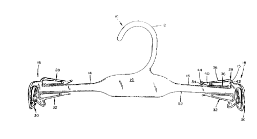
Referring now in detail to the drawings,
Figures 1 and 2 illustrate respectively front and rear
elevational views of a molded plastic garment hanger
10 having a central hook member 12 which is integrally
molded with an elongated hanger body 14, the latter of
which includes a pair of coplanar oppositely directed
ends 16 and 18, with each of the ends defining a
plurality of garment retaining clips for suspending
one or more garments. The particular illustrated
shapes of the central hook member 12 and elongated
hanger body 14 are exemplary only, and can have
various and different shapes and dimensions. The
shaded areas in Figure 3 are all formed with a reduced
width w, reduced from the full width W, as illustrated
in Figures 4 and 5.
As depicted best in Figures 1, 2 and 4, to
maximize strength while using the minimum amount of
CA 022~8296 l998-l2-l~
WO98/~051 PCT~S97/07434
-12-
material, the hanger body 14 and the central hook
l member 12 are constructed with a C-shaped cross-
section having a first horizontally extending flange
20 and a second horizontally extending flange 22
connected by a vertical wall 24. However, in
alternative embodiments the hanger body 14 may be
constructed with a curved M-shaped cross-section, an
E-shaped cross-section, an I-beam cross-section, or
any suitable cross-section which may improve the
strength to weight ratio for particular applications
to resist flexing due to the weight of the garment
hanging from the hanger of the present invention and
to assist in maintaining the hanger upright when in
use.
The plurality of garment retaining clips can
include one or more of a first garment retaining clip
28, a second garment retaining clip 30, and a third
garment retaining clip 32. The first garment
retaining clip 28 is generally horizontally disposed
above the body member 14. The second garment
retaining clip 30 is generally vertically disposed,
with an inward slant as described in greater detail
hereinbelow, and is disposed outwardly from the end 16
or 18. The third garment retaining clip 32 is
generally horizontally disposed below the hanger body
14. The horizontally disposed garment retaining clips
28 and 32 typically receive shoulder straps from a
brassiere, slip or like garment. The generally
vertically disposed second garment retaining clip 30
typically receives a waistband from panties, swimsuit
bottoms or like garments.
I
CA 022~8296 1998-12-1~
W098/00051 PCT~S97/07434
The hanger body 14 is constructed with a C-
l shaped cross-section having a generally flat central
section 24 and reinforcing flanges 20, 22 extending
around the edges of the central section which define
the width of the garment hanger. The primary support
members of the plurality of garment retaining clips
28, 30 and 32 are generally constructed of the same
width W as the reinforcing flanges 32, as described in
further detail hereinbelow. As illustrated in Figure
2, the top flange 20 extends upwardly at 33 and
continuously into the structure of the first garment
retaining clip 28 and one side of the second garment
retaining clip 30, which have the same width W as the
flange 33. The bottom flange 22 extends downwardly at
35 and continuously into the structure of the third
garment retaining clip 32 and the second side of the
second garment retaining clip 30, which also have the
same width W as the reinforcing flange.
As illustrated in Figures 1-3, the first
garment retaining clip 28, which is positioned above
and adjacent to the body member 14, defines a first
garment receiving channel or mouth 34 therebetween.
The first garment receiving clip 28 has a resilient
substantially V-shaped, double return configuration
comprising a first elongated member 36 and a second
elongated member 38 integrally connected in a spaced
V-shaped relationship by a connecting portion 40.
When a garment is inserted into the first garment
receiving channel 34, the second elongated member 38
deflects into a deflecting area 42 while it serves to
hold the garment in place. The deflecting area 42 is
... . .. ... . ... . . .
CA 022~8296 1998-12-l~
WO98/00051 PCT~S97/07434
-14-
defined by the first elongated member 36, the second
1 elongated member 38 and the connecting portion 40.
The first garment retaining clip 28 is designed and
configured such that the second member 38 is moveable
in a direction transverse to and from the body member
14 while resisting movement into and out of the plane
of the hanger body 14. To facilitate the insertion of
a garment to be suspended from the hanger, the
connecting portion 40 is formed with a rounded lip 44
which extends upwardly and inwardly toward the hook
member 12-
The first garment retaining clip 28, withthe V-shaped members 36, 38, provides a construction
having two primary resilient mounts, the first
resilient mount being the cantilever mounting at 46 of
the first member 36, and the second resilient mount
being the cantilever mounting at 40 of member 38
relative to member 36. The construction of the first
and second members 36, 38 is further illustrated in
Figure 4, which illustrates the rounded rectangular or
oval shape of each of the first and second members 36,
38.
The first and second members 36, 38 are both
constructed to have the same width W as the hanger
body 14, which resists movement of the members 36, 38
into and out of the plane of the hanger body. This is
in contrast to a prior art design in which a member
similar to member 38 was constructed with a reduced
width, which resulted in substantial movement of the
member into and out of the plane of the hanger body.
Figures 3 and 4 also illustrate a center stiffening
CA 022~8296 1998-12-l~
WO98/00051 PCT~S97/07434
rib 50 connecting the first and second members 36 and
1 38 near the cantilever mounting 40 which stiffens the
cantilever mounting, and also resists movement of
member 38 into and out of the plane of the hanger
body.
The construction and design is such that as
a garment or strap is initially inserted into the
mouth of the first garment receiving channel 34, as
illustrated in Figure 6, an initial expansion at the
mouth of the garment receiving channel caused by
insertion of the garment therein causes a rotation of
the combination of the first and second members 36, 38
about the first cantilever mount 46. As illustrated
in Figure 6, during the initial insertion the first
member 36 bends upwardly, with the upward bend most
pronounced nearer to the cantilever mounting at 46.
As the garment or strap slides past the second
cantilever mount 40 and towards the free end 48 of the
second member 38, as illustrated in Figure 7, it
causes an upward flexure of the free end 48 of the
second member 38, which also results in a downward
deflection of the free end of the first member 36 at
40 and a closing of the bottom of the second member 38
near the location at 40 relative to the hanger body 14
positioned therebeneath.
As illustrated in Figure 7, when the garment
clip is closed upon a garment, the top member 36
frequently assumes a complex curved shape, initially
bowing downwardly at 71, and then bowing up very
slightly at 73, then bowing continuously downwardly at
75 towards the connecting position 40.
CA 022~8296 1998-12-l~
WO98/00051 PCT~S97/07434
-16-
Accordingly, as a garment or strap is
1 inserted into the first garment retaining clip 28, the
compound mounting and action of the first and second
members 36, 38 result in the mouth of the clip first
opening to allow the garment to enter, and then
closing to securely retain the garment or strap
therein to prevent it from being accidentally
dislodged and falling from the first garment retaining
clip. This advantageous feature of automatic closing
of the mouth of the garment retaining clip against a
garment or strap after the garment or strap has been
inserted therein is novel relative to known prior art
garment retaining clips.
Moreover with such molded plastic garment
hangers, garments are frequently inserted into the
garment clips manually by a person who inserts a great
number of garments into a corresponding number of
garment clips. Prior art garment clips have been
designed with additional strength and stiffness to
prevent breakage of the garment clips as a garment is
inserted therein or removed therefrom. The additional
strength and stiffness has often been achieved by
designing the moveable arm or arms of the garment clip
with a stiffening, reinforcing outer rib extending
longitudinally along the outer length of the moveable
arm, similar to the reinforcing outer rib 58 of the
garment clip 30 illustrated in Figures 3 and 5. With
the stiffer, more rigid clips typical of the prior
art, the persons inserting the garments into the
garment clips frequently developed carpel tunnel
syndrome because of the constant strain associated
CA 022~8296 1998-12-1~
WO98/00051 PCT~S97/07434
with inserting a large number of garments,
l particularly thicker garments, into the garment clips.
The present invention takes an opposite
approach in which the garment clip is designed with
- greater flexibility, without a stiffening rib
extending longitudinally along the length of the
moveable clip arm. The more flexible clip arm is much
easier to open and use by a customer, and moreover the
greater flexibility results in almost no breakage of
the clip arms. The greater flexibility is achieved by
eliminating a stiffening rib, and also by designing
the garment clip with a double return configuration as
explained hereinabove.
The garment retaining clip of the present
invention is designed to be much more flexible and
easier to open and use than previous prior art
designs. The more flexible design is achieved by the
double return configuration and functioning of the
garment clip as described hereinabove, and by a
careful designing of, the garment dimensions, ratios
of the dimensions, and selection of an appropriate
material.
The inventive plastic hanger can be formed
of styrene which provides a clear, virtually
transparent polystyrene hanger for maximum display of
intimate apparel garments, such as bras and panties,
to be suspended therefrom. In the alternative, the
hanger can be molded from polypropylene; preferably
II.I, styrene polypropylene; polypropylene;
polyvinychloride; ABS or other suitable thermoplastics
3o
CA 022~8296 1998-12-1~
WO98/0~51 PCT~S97/07434
-18-
and mixtures thereof. For additional reinforcement, K
l resin can be added to the plastic material.
The preferred material polystyrene has a
Flexural Modulus, MPa, of 3,170, taken from CONCISE
ENCYCLOPEDIA OF POLYMER SCIENCE AND ENGINEERING, p.
1117-
In one preferred embodiment, the firstgarment clip 28 has the following dimensions shown in
the left column, which can vary in alternative
embodiments between the lower and upper limits shown
respectively in the middle and right columns,
W = 0.190" 0.14 0.24
T1 = T2 = 0.078" 0.06 0.10
Ll = 0.890" 0.67 1.11
L2 = 0.807" 0.60 1.01
A = 0.318"
B = 0.130"
C = 0.414"
The garment clip 28 has the following ratios
of dimensions shown in the left column, which can vary
in alternative embodiments between the lower and upper
limits shown respectively in the middle and right
columns.
W/T = 2.436 1.8 3.0
L1/T = 11.410 8.514.3
L2/T = 10.346 7.713.0
Ll/W = 4.684 3.5 5.9
L2/W = 4.247 3.2 5.3
The third garment retaining clip 32 is
constructed similar to the first garment retaining
clip 28, and accordingly functions in a manner similar
CA 022~8296 1998-12-1~
WO98/~51 PCT~S97/07434
--1 9--
to that explained above for the first garment
l retaining clip.
The third garment clip 32 has the following
dimensions, shown in the left column, which can vary
in alternative embodiments between the lower and upper
limits shown respectively in the middle and right
columns
W = 0.190" 0.140.24
T3 = T4 = 0.078" 0.06 0.10
L~ = 0.950" 0.71 1.19
~~ L4 = 0.876" 0.66 1.11
D = 0.321"
E = 0.130"
F = 0.363"
The third garment clip 32 has the following
ratios of dimensions shown in the left column, which
can vary in alternative embodiments between the lower
and upper limits shown respectively in the middle and
right columns
W/T = 2.436 1.8 3.0
L3/T = 12.179 9.1 15.2
L4/T = 11.231 8.4 14.0
L3/W = 5.000 3.8 6.2
L4/W = 4.611 3.5 5.8
The above dimensions and ratios have been
found to provide garment clips constructed of
polystyrene which are particularly efficacious and
useful. However, other suitable plastic materials
having a different Modulus of Elasticity (Young's
Modulus) than polystyrene may be utilized in
3o
.. . . . . .
CA 022~8296 1998-12-1~
W098/00051 PCT~S97tO7434
-20-
alternative embodiments with suitable modifications of
1 the garment clip ~imen.~ions and ratios of dimensions.
Referring to Figure 3, the second garment
retaining clip 30 is integrally molded with the hanger
body at each of the first and second ends. Each
second garment retaining clip comprises first and
second opposed clip sides defining a garment receiving
channel 52 therebetween. The second garment retaining
clip 30 is designed to mount panties, and includes
several novel features. The V at 53 defining the
mouth of the garment receiving channel 52 of the
second garment retaining clip defines a larger opening
than the mouths of known prior art garment retaining
clips, which makes it easier to mount panties on the
garment hanger. The first clip side comprises a first
downwardly extending support member 54 mounted to the
end of the body member by a first cantilever mount at
55 and having a spaced end. The construction of the
first support member 54 of the panty holder is also
novel, and provides a relatively inflexible mount for
the outer rib, which provides a relatively stiff and
inflexible support as a panty band is inserted into
the second garment retaining clip.
The first support member 54 has a rounded
rectangular shaped member 56, as illustrated in
section in Figure 5, having the same width W as the
hanger body 14. Additionally, a center stiffening rib
58 extends longitudinally along the outer length of
support member 54. The first support member 54
extends to a spaced end at 60 which forms a cantilever
support and mount for a second support member 62. The
CA 022~8296 l998-l2-l~
WO98/0~51 PCT~S97/07434
-21-
second member 62 also has a rounded rectangular shape,
l as illustrated in section in Figure 5, having the same
width W as the hanger body. A center rib 64 extends
longitudinally along the inner length of support
member 56, and extends into a center cantilever
5 support 66 for the second member 62. The second
member 62 defines a center toothed section 68.
The second clip side comprises a downwardly
extending member which is positioned opposed to and
spaced from the first clip side to define the garment
receiving channel 52 therebetween. The reinforcing
flange 22 of the hanger body 14 extends downwardly at
70 into a support member 72, having the same width W,
which extends downwardly to form the second opposed
side of the second garment retaining clip. The
support member 72 extends downwardly, and then
inwardly at 74 where it extends into and forms a part
of the third garment retaining clip 32. A support
member 76, having a width W, extends downwardly from
support member 72, and then curves around and extends
outwardly at 78. A center rib 80 defines a center
toothed section 82, spaced and opposed to the center
toothed section 68, to form the garment receiving
channel 52 therebetween to grasp and retain a garment
therein.
A further novel feature of the second
garment retaining clip is the inward slant defined by
the garment receiving channel 52 of the panty
retaining clip. As a panty waist band is inserted
into the second garment retaining clip and is inserted
from an initial position at location 86 to a fully
.
CA 022~8296 1998-12-1~
WO 98/00051 PCT/US97/074;54
inserted position at location 88, the panty waist band
1 moves radially inwardly towards the center of the
garment hanger a distance d, Figure 6, of
approximately 1/8 inch. This means that after a panty
waist band is inserted fully into the panty retaining
clip, the panty waist band shrinks approximately 1/8"
at each end of the garment hanger. This also means
that the panty waist band must be expanded or
stretched 1/4", 1/8" at each end of the garment
hanger, to remove the panty from the panty retaining
clip, which makes accidental removal or dislodgement
of the garment from the garment clip a virtual
impossibility.
A novel feature of the second garment
retaining clip 30 is the reinforcing outer rib 58
which extends along the length of and reinforces the
first support member 58 to make the first support
member more rigid and less resilient, and also the
inner reinforcing rib 64.
While several embodiments and variations of
the present invention for a garment hanger are
described in detail herein, it should be apparent that
the disclosure and teachings of the present invention
will suggest many alternative designs to those skilled
in the art.
3o
, _ 1