Note: Descriptions are shown in the official language in which they were submitted.
CA 02258603 1999-OS-14
WO 98/02727 PCT/US97111105
1
MET80D AND APPARATUS FOR
PERFORMING AUTOMATED ANALYSIS
These embodiments relate in general to particle
analysis. More particularly, they relate to methods and
devices for performing automated blood cell analysis by
integrating "impedance," "light scattering," and ,
"fluorescence" analysis and flow cytometric techniques.
These embodiments also relate to a multipurpose reagent
system and a method for rapid analysis of a whole blood
sample.
Peripheral blood of a human usually contains red blood
cells (RBC); platelets (PLT), and whine blood cells (wBC),
all of which are suspended in a conductive medium commonly
known as plasma. Plasma comprises proteins, anions and
cations. Plasma also contains components which assist in
forming blood clots.
CA 02258603 1998-12-16
WO 98/02727 PCT/US9?/11105
2
The blood in an adult usually contains about 4.5 to 5
million RBCs or erythrocytes per cubic millimeter. Mature
RBCs have no nuclei and are generally shaped as circular
biconcave disks with a diameter of about 7.5 to 8 microns
(E.t), and a thickness of about 1.5 to 1.8 microns. RBCs
contain hemoglobin which gives blood its red color.
Hemoglobin helps transport oxygen and carbon dioxide and
plays a role in maintaining pH in blood.
The blood in an adult usually contains about 200,000 to
20 400,000 platelets per cubic millimeter_ Platelets are small,
biconvex cellular particles whose mean volume is about 7~.~. to
8)..~.. Their general configuration includes a granular central
portion embedded in a homogeneous matrix.
Peripheral blood also contains red cells of earlier
- maturation levels which are important diagnostic indicators.
Two of these are reticulocytes and nucleated red blood cells.
At the earliest stage of development the red cell
consists mostly of nucleus, and is referred to as an
erythroblast. As the erythroblast matures, the nucleus
becomes smaller, anucleolate, and more nearly spherical.
Subsequent maturity involves a complete loss of nucleus. The
immature red cells that retain a nucleus are referred to as
nucleated red blood cells (NRBCs). The NRBC count has been
useful in patient monitoring under many disease states.
However, NRBCs in peripheral blood often contribute to
inaccurate enumeration of the white cell count, due in part
to the presence of a nucleus which makes them difficult to
distinguish from small white cells_
Reticulocytes are red cells at the maturation level just
between NRBCs and mature RBCs. Reticulocytes provide a means
of evaluating a patient's anemic state. Anemia usually
occurs as a result of an uncompensated increase in the rate
of removal of erythrocytes from blood, or a decrease in the
rate at which they are formed and released into blood. An
increased reticulocyte patient count in an anemic patient
CA 02258603 1998-12-16
WO 98/02727 PCT/US97/11105
3
indicates rapid erythroid turnover which suggests acute blood
loss or hemolysis.
In normal human blood, the concentration of white cells,
referred to as WBCs or leukocytes, is much lower than the
concentration of red cells. The normal concentration of WBCs
is approximately 7000 per microliter. They vary in size,
most of them from about 7,5 to 12.5 microns in diameter.
They are more nearly spherical in shape than RBCs and usually
somewhat larger in volume. WBCs may be classified generally
as either granular or non-granular. The granular WBCs
include neutrophils, eosinophils and basophils. The non-
granular WBCs include monocytes and lymphocytes. These
categories of WBCs are often referred to collectively as a
"five-part differential," and, generally, the most
significant of these categories are neutrophils-and
lymphocytes.
Neutrophils usually comprise from about 50 to 600 of all
WBCs. Their cytoplasm contains numerousminute granules
which can be stained. Under certain conditions neutrophils
may leave the blood vessels and disintegrate, thereby
releasing granules into the connective tissues. These
granules are rich in certain enzymes which become active and
take part .in the body's defense mechanism.
Lymphocytes comprise about 30oof the WBCs in humans.
The nucleus of a normal lymphocyte occupies nearly the entire
cell volume, and thus the cytoplasm surrounding the nucleus
is a rather thin shell. Lymphocyte cytoplasm may stain with
dyes due to the cytoplasm's content of ribonucleic acid.
Lymphocytes may leave the blo-od vessels and enter the
connective tissue where they also constitute a part of the
body's defense mechanism, playing a major role in the body's
immunological responses.
There are three major "subsets" of lymphocytes that are
currently clinically significant: T lymphocytes, B
lymphocytes, and Natural Killer cells, also known as "large
CA 02258603 1998-12-16
W~ 98/02727 PCT/US97/I1105
4
granular lymphocytes" or NK cells. Each of these subsets can
be distinguished based on the existence of distinctive cell ,
surface markers or antigens. Also, B lymphocytes have a high
density of immunoglobulin of their surfaces, whereas T
lymphocytes have little or none. T lymphocytes are
characterized by various surface markers against which
antibodies can be produced.
Categories of T lymphocytes have been identified
according to their surface markers and overall function. The
"helper" T cells help B cells produce certain classes of
antibody molecules, and help other T cells in their immune
responses. The "suppressor° T cells are regulatory cells
that can suppress the responsiveness of other T or s cells.
The suppressor T cells include several subsets which are also
recognized by distinct surface markers.
The ability to count, size and classify blood cells is
useful when evaluating the health of an individual. For
example, the level of circulating CD4 lymphocytes (helper-T
cells having a CD4 antigen expressed on the surface of the
cell) is currently regarded as the best single predictor of
progression of HIV infections. The CD4 level may be used for
classifying individuals for enrollment in experimental
treatment regimes, determining when anti viral therapy should
be initiated, and monitoring treatment responses in clinical
trials. Because CD4 lymphocyte levels may be important to
some HIV-infected individuals, it is desirable to measure
this parameter accurately.
In the current state of_ the art-. of r_ell analysis, there
are two technologies used for counting and classifying cells.
These are generally known as "flow cytometry" and "image
cytometry." The flow cytometry technology, which essentially
consists of passing cells one at a time through a sensing
zone of a flow cell, is preferred in clinical applications
where patient test load is an important metric. This is
mainly because it has at least an order of magnitude
CA 02258603 1998-12-16
WO 98/02727 PCT/U897/11105
advantage in the number of cells that can be analyzed per
second.
Instrumentation incorporating flow cytometry can be
further subdivided into two methods which can be generally
5 classified as "conventional hematology" and "fluorescence
cytometry."
A primary distinction between the two methods is that
conventional hematology generally distinguish cells by means
of size and shape alone using primarily impedance and light
scatter technologies, whereas fluorescence cytometry uses
cell nucleic acid content and/or surface antigens in addition
to size and shape in distinguishing cells. Therefore the
fluorescence method may be used to subdivide the cell types
into finer classifications.
A second distinction between the two methods is that
conventional hematology gives results in absolute terms,
whereas fluorescence cytometry results are i~ relative terms.
Hematology analyzers deliver precise volumes and dilutions,
and are thus able to measure absolute cell concentrations, or
absolute counts of cell types per microliter of human blood.
The fluorescence cytometry method gives only relative
concentrations, or percentages of the various cell types.
A third distinction is that the hematology method is
generally automated, whereas the fluorescence cytometric
method as generally practiced today, is at best semi-
automated, both in sample preparation, and in sample
analysis. The fluorescence cytometry method is therefore
significantly more labor intensive than the hematology
method.
Both methods use cell by cell analysis. Therefore, due
to the high concentration of cells in whole blood, it is
necessary to dilute the blood samples prior to analysis so
that individual cells can be isolated for sensing within a
flowcell.
CA 02258603 1998-12-16
WO 98/02727 PCT/US97/i1105
An example of an instrument for performing automated
hematology measurements is the Cell-Dyn~ 3000 instrument,
which has been sold for several years by Sequoia-Turner, a
predecessor in interest of Abbott Laboratories. The Cell-
s Dyn~ 3000 instrument uses "impedance" measurements to count
and size RBCs and PLTs, "absorption" measurements to
determine the concentration of hemoglobin in RBCs tMCH), and
"optical scatter" measurements to count and classify wBCs and
the five part differential.
The Cell-Dyn~ 3000 instrument automatically prepares
blood samples, measures cell parameters and generates test
results. The complete automation of sample preparation is
such that no substantive operator intervention is required
once the patient sample of whole blood has been presented to
the analyzer. As mentioned previously, in order to assure
accurate "patient counts" for the vax ic~L~:; cell classes, t~he~
Cell-Dyn~ 3000 instrument provides precise sample volumes,
reagent volumes and dilution volumes. Patient counts are
generally defined as the number of "events" per microliter of
blood. The events may be RBCs, PLTs, wBCs, and classes or
subclasses thereof_
Other commercially available devices for performing
hematology measurements include the Coulter~ STKR, the
Sysmex~ NE8000, and the Technicon~ H-1. Each of these uses
combinations of scatter, impedance, and absorption to
distinguish and quantify cells, and can thus be classified as
a conventional hematology instrument.
In contrast, the fluorescence flow cytometer
incorporates the principles of fluorescence cell analysis
with light scatter_ In general this requires that the cell
be stained with an appropriate color dye, or that a
fluorochrome label be attached to an antigen or antibody on
the cell's surface thus indicating the occurrence of a
specific antigen-antibody reaction.
CA 02258603 1998-12-16
WO 98/02727 PCT/US97/11105
7
In fluorescence flow cytometry, a suspension of
previously stained or fluorescently labelled particles,
typically cells in a blood or other biological fluid sample,
is transported through a flowcell where the individual
particles in the sample are illuminated with one or more
focused light beams. One or more detectors detect the
interaction between the light beams) and the labeled
particles flowing throughthe flowcell. Commonly, some of
the detectors are designed to measure fluorescent emissions,
20 while other detectors measure scatter intensity or pulse
duration. Thus, each particle that passes through the
flowcell can be mapped into a feature space whose axes are
the emission colors, light intensities, or other properties,
i.e. scatter, measured by the detectors. Preferably,the
different particles in the sample can be mapped into distinct
and non-overlapping regions of the feature space, allowing
each particle to be analyzed based on its mapping in the
feature space. In this respect, flow cytometry differs from
the conventional hematology instruments in that some of the
feature space axis includes fluorescence emissions.
As noted above, lymphocyte subclasses are health
determinants. Thus, it is desirable that these and other
parameters be measured accurately. Although known hematology
and fluorescent flow cytometry instruments have made
significant advances in the ability to characterize blood
cells, a problem still faced in this area is the difficulty
in obtaining accurate patient count values for certain
classes of cells.
An example of thisproblem is the CD4 cell patient
count. Current analysis methods calculate the CD4 cell
patient count from cell parameters measured on a hematology
instrument and a separate fluorescence flova cytometry
. instrument. This calculation can provide up to 100%
variability in absolute CD4 patient counts done on a single
individual one week apart_ See, e.g.. Update, Testing In The
CA 02258603 1999-OS-14
WO 98/02727 PCT/US97/1I105
8
Blood Bank, Volume 5. No. 2, pages 1 to 6, published 1991 by
Ortho Diagnostics Systems, Inc.
The following articles discuss additional difficulties
with developing CD4 patient counts using current methods and
devices;
The Lancet, Volume 340, August 22, 1992, page 485
describes variation in CD4 count results when
different analyzers are used. The variation '
appears to stem from different lymphocyte count
results.
Journal of Infectious Diseases, 1990, Volume 161,
pages 356 to 357 describes variations in CD4 count
_ due to variability in the reported lymphocyte
concentration. The resulting variation in CD4
results has a deleterious effect on the patients'
morale:
Journal of Acquired Immune Deficiency Syndromes,
1990, Volume 3. No. 2, pages 144 to 181 reports
large variations in CD4 counts for both HIV
positive and control subjects. The fraction of
lymphocytes that are CD4 positive is relatively
constant, while the wBC count and the fraction of
WBCs that are lymphocytes vary greatly. This
variability points to the need for standardized
analysis procedures. ,
Laboratory Medicine, August 1983, Volume 14, No. 8,
' pages 509 to 514 discusses numerous spurious
results and their causes in automated hematology
analyzers.
One reason for variability in CD4 patient counts is
manual sample preparation that cannot be controlled precisely
and depends on operator proficiency. For example, a
conventional procedure for determining a CD4 patient count
CA 02258603 1998-12-16
WO 98/02727 PCT/US97/11105
9
starts with drawing two tubes of blood from ,a patient. One
tube is analyzed on a hematology instrument which generates
several measured and/or calculated parameters for the blood
sample, including a total lymphocyte patient count, a
S lymphocyte percentage and a total WBC patient count. The
second tube of blood is analyzed on a fluorescence flow
cytometry instrument. The sample preparation steps for the
flow cytometry tests are labor intensive and operator
dependent. These steps do not readily lend themselves to
automation and precision.
To prepare the sample for the flow cytometry instrument,
the operator manually pipettes a volume of blood from the
sample tube into an analysis tube. A volume of the desired
fluorochrome labeled monoclonal antibody is added. The
sample/antibody mixture is then incubated for a predetermined
time at a predetermined temperature to allow antibody/antigen
bindings to take place- After incubation, the operator adds
a volume of RBC lyre to destroy the RBCs in the sample.
Timing is important during the lysing stage. If the operator
does not allow the lyse reaction to continue long enough,
RBCs may remain in the sample and distort the measurements.
If the operator allows the lyse reaction to continue for too
long, the lyse may attack the WBCs.
After determining that the lyse reaction is complete,
the operator centrifuges and washes the sample to remove any
debris left over from lysed RBCs. The centrifuge/wash step
may be performed several times until the operator is
satisfied that the sample is sufficiently clean. Debris, red
cell "stroma" can interfere with the detection processes of
the typical flow cytometer. The sample now contains WBCs
> with antibodies bound to cells bearing the complementary
surface antigens. The operator re-suspends the sample in a
volume of fixative, and then passes the sample through the
fluorescence flow cytometry instrument.
CA 02258603 1998-12-16
WO 98/02727 PCT/1TS97/11105
The fluorescence flow cytometry instrument generates
only percentage values for lymphocyte subsets. This is at
least partially due to the fact that the numerous manual
dilutions and volume reductions performed during the sample
5 - preparation steps do not allow the isolation of a precise
measurement volume. Thus, the fluorescence flow cytometry
instrument identifies the CD4 positive helper-T cells as the
percentage of lymphocytes which are both positive for CD3 (T
cell marker), and positive for CD4thelper-T marker).
10 The CD4 patient count is then calcula-ted using the
following equations:
(glymph/100)X(WBC count) - lymph count
(helper-T in lymph/100) x lymph count = CD4 count
The lymph count and the WBC patient count are taken from the
hematology instrument, while the "~ helper-T cells in lymph"
value is taken from the fluorescence instrument after a
correction factor is applied based on the flow cytometer
mapping of scatter and fluorescence.
There are several problems with the current methods of
calculating patient count values for lymphocyte subsets.
First of all, the calculation is based on values obtained
from separate instruments that each have their own
calibration and overall separate functions. Additionally,
different testing methods may be used on the different
instruments.
Not only are hematology instrument measurements
different from fluorescence instrument measurements, but also
there may be variations in results obtained from different
hematology instruments. t
Previous attempts to automate sample preparation in
fluorescence cytometry testing have only been partially
successful. Such systems still require the operator to
_ perform sample preparation steps such as separating
CA 02258603 1998-12-16
WO 98/02727 PCTlUS97l11I05
11
lymphocytes from other peripheral blood cells by density
gradient centrifugation, and/or lysing red cells, removing
red cell ghosts and cell debris by centrifugation, or
preserving the morphology of the remaining white cells by
suspending the white cells in an isotonic saline solution
containing appropriate fixatives. These operations generally
require the operator to manually alter the volume of the
sample, thus compromising sample volume precision which can
be achieved with automated mechanical volume dispensers.
Another problem with the present technique of doing the
measurements on separate instzwmPnt-., it that a relatively
large volume of patient blood is needed to fill two tubes.
This is a problem because of the increased likelihood that
the blood will become hemolyzed (red cells destroyed) as
larger amounts of blood are drawn. Additionally, it may not
be advisable or possible to draw a sufficient amount of blood
from certain patients.
In leukocyte analyses, it is desirable that all of the
RBCs be lysed. Because RBCs outnumber WBCs by about 700 to
1, a small number of unlysed red cells may significantly -
distort white cell patient counts. Some reagents used to
lyse red cells require too lengthy an incubation period to be
practical in an automated clinical analyzer. For example,
the Tris buffered ammonium chloride solution recommended by
K.A. Murihead in Clinical Cytometry, Ann.N.Y. Acd. Sci., vol.
468, pp. 113-227 (1986) takes about 5 to 10minutes to lyse
red cells, which may be impractical for automation.
Furthermore, incomplete hemolysis with certain lytic
reagents may result in red cell stroma that retain sufficient
hemoglobin or particulate matter to generate high background
patient counts in automated clinical electro-optical systems.
When this occurs, it is usually necessary to remove the WBCs
' to be analyzed from the red cell stroma by centrifugation, a
procedure that is a limiting factor when adapting a reagent
system for automation.
CA 02258603 1998-12-16
WO 98/02727 PCT/US97/11105
12
Some currently used reagent systems require cytochemical
staining of fixed WBCs before differential analysis. These
systems require timed addition of multiple reagents and
incubation periods and may not be generally adaptable for
- quantifying nucleated red cells or lymphocyte subsets.
Furthermore, each step of reagent addition or other
manipulation of a blood sample may decrease the precision of
the final patient count obtained.
The earliest stage of RBC, the nucleated red cell, NRBC,
when found in the peripheral blood on conventional hematology
analyzers can be confused for a small lymphocyte, since the
lysis will not destroy the nucleus of the NRBC. Because of
the ratio of RBCs to WBCs, even a relatively small percentage
of NRBCs can lead to substantial error in the WBC and
lymphocyte count. This may be troublesome in neonate or
pediatric samples, in which the presence of NRBCs in
peripheral blood is a normal condition. For this reason, the
laboratory may do manual slide inspections on some of these
samples. Conventional hematology analyzers are only able to
flag these samples by noting the spreading out of the usual
lymphocyte scatter cluster. The manual inspection results in
a count of the number of NRBCs per 100 nucleated cells. This
percentage is then used to correct the analyzer WBC count as
follows:
Corrected WBC count = Analyzer count(1-manual NRBC
percentage/100)
Clearly the need exists for an accurate automated count
of NRBCs.
Another important class of immature red blood cells are
"reticulocytes" which typically contain detectable amounts of
RNA. A manual method of identifying and counting _
reticulocytes involves precipitating the RNA with a stain. A
smear is pulled from the stained blood and manually examined
CA 02258603 1998-12-16
WO 98/02727 PCT/US97/11105
I3
under a microscope. The precipitated RNA appears as
intracellular dots or filaments. Reticulocyte ~ is
determined by manually counting 1,000 RBCs under a microscope
and dividing those qualifying as reticulocytes by 10. The
' 5 reticulocyte patient count is derived from the RBC patient
count according to the following equation:
Reticulocyte count = (RBC count)x(percent reticulocytes)/100
Both the precision and the accuracy of this manual
method are less than desirable. There may be considerable
variation in identification of reticulocytes as well as
variation in counting techniques. Accordingly, there is a
need for a cell analysis system that addresses the
deficiencies described above.
Platelet counts are also a health determinant. Some
hematology analyzers, such as the CELL-DYN~ 3000 and others
mentioned earlier, count platelets by an impedance method.
This method has limitations when the platelet count is
reduced, such as about less than or equal to about 50,000 per
~t.l. These limitations may include lack of precision due to
the relatively few platelets counted, inaccurate results due
to the only one dimensional measurement provided by the
impedance transducer, etc. Further, because of the one
dimensional measurement, the analysis may confuse other cell
fragments with platelets as they pass through the impedance
sensing chamber. Thus, improvements in platelet analysis are
also desired.
CA 02258603 1998-12-16
WO 98/02727 PCT/iJS97/11105
14
Provided are automated methods for_distinguishing and
differentiating cells in a whole blood sample. In one of the
methods, a whole blood sample is provided. One or more tests ''
to be performed on the whole blood sample is selected. The
tests to be performed on the who7_e blood sample are
correlated. A volume of the whole blood sample is aspirated
into an automated instrument system which automatically
performs conventional hematology analysis and fluorescent
cytometry analysis on the whole blood sample. A first
aliquot of the whole blood sample .is dispensed into at least
one sample receiving vessel. The first aliquot of the whole
blood sample is mixed with a fluorescent reagent_ The first
aliquot of the whole blood sample mixed with fluorescent
reagent is diluted and transported through a flow transducer
system. The flow transducer system detects multi-angle light
scatter and fluorescence from the first aliquot of the whole
blood sample mixed with fluorescent reagent and counts and
differentiates platelets or platelet clumps or both in the
sample. Detecting and differentiation data for the one or
more tests performed on the whole blood sample are stored.
Results of the one or more tests performed-on-the whole blood
sample are reported in a quantitative manner if so requested.
The instrument system automatically performs-all method steps
without physically separating cells from the whole blood
sample or an aliquot of the sample and results of a
conventional hematology analysis may be utilized in at least
reporting of results of the fluorescent cytometry testing.
In another method, a whole blood sample is provided. A
series of two or more tests to be performed on the whole
blood sample is selected. The tests to be performed on the
whole blood sample are correlated. A first volume of the
whole blood sample is aspirated into an automated instrument
system which performs conventional hematology analysis and
CA 02258603 1998-12-16
WO 98/02727 PCT/US97I11105
fluorescent cytometry analysis on the whole blood sample.
Aliquots of the whole blood sample are dispensed into at
least three sample receiving vessels. A first aliquot of the
whole blood sample is diluted with a diluent reagent. A
5 second aliquot of the whole blood sample is lysed with a
lysing reagent. A third aliquot of the whole blood sample is
mixed with a fluorescent reagent. The first aliquot of
diluted whole blood sample is transported through a flow
transducer. The instrument flow transducer detects and
10 counts red blood cells and platelets in the first aliquot of
diluted whole blood sample. The second aliquot of lysed
whole blood sample is transported through a flow transducer
system. The flow transducer system detects mufti-angle light
scatter from the second aliquot of iysed whole blood sample
15 and counts and differentiates white blood cells in the second
aliquot of whole blood sample. The flow transducer system
detects mufti-angle light scatter and fluorescence from the
' second aliquot of lysed whole blood sample or the first
aliquot of diluted whole blood sample and counts and
differentiates nucleated red blood cells or reticulocytes or
both therein. The third aliquot of the whole blood sample is
transported through a flow transducer system. The flow
transducer system detects mufti-angle light scatter and
fluorescence from the third aliquot of whole blood sample and
counts and differentiates platelets or platelet clumps or
both therein. The instrument stores detecting and
differentiating data for multiple tests performed on the
whole blood sample. The instrument reports results of each
of the multiple tests performed on the whole blood sample in
a quantitative manner if so requested. The instrument system
automatically performs all method steps without physically
separating cells from the whole blood sample or an aliquot
thereof and results of the conventional hematology analysis
may be utilized in at least reporting of results of
fluorescent cytometry testing
CA 02258603 1998-12-16
WO 98102727 PCTlUS97/11105
16
~RTFF DESCRIPTION OF THE DRAVJTNGS
Figure 1 is a block diagram of a cell analysis system
constructed according to teachings of the present invention;
Figure 2 is a block diagram of an embodiment of a
software subsystem used with the cell analysis system shown
in Figure 1;
Figure 3 illustrates one embodiment of a sample
processing area of the cell analysis system shown in Figure
1;
Figure 4 is a more detailed diagram of the sample
processing area shown in Figure 3;
Figure 4A is front elevational view of a vent/aspirate
assembly of the system shown in Figure 4;
Figure 4B is a perspective view of an incubation probe
assembly used in the system of Figure 4;
Figure 5 is illustrates one embodiment of a fluid
distribution system of the cell analysis system shown in
Figure 1;
Figures 6a, 6b, and 6c illustrate the incubation probe
of the cell analysis system during deposition, cleaning and
aspiration;
Figure 7 is a diagram illustrating one embodiment of an
aspiration and deposition system of the cell analysis system
shown in Figure 1;
Figure 8 is a diagram illustrating one embodiment of an
incubation transfer system of the cell analysis system shown
in Figure 1;
Figure 9 is a diagram illustrating one embodiment of a ,
reticulocyte stain delivery system of the cell analysis
system shown in Figure 1;
Figure 10a is a diagram illustrating one embodiment of
an impedance sample delivery system of the cell analysis
CA 02258603 1998-12-16
WO 98/02727 PCT/LTS97/11105
17
system shown in Figure 1. In this view, the valves are open,
and the sample is being transferred in bulk to the impedance
transducer proximity via the pump 220;
Figure 10b is a diagram of the impedance sample delivery
h
system shown in Figure 10a. In this view, the valves are
closed, and a volume of the sample is being metered to the
impedance transducer;
Figure 11a is a diagram illustrating one embodiment of
an optical sample delivery system of the cell analysis system
shown in Figure 1. In this view, the valves are-open, and
the sample is being transferred in bulk to the flow cell
proximity via the pump 232;
Figure 11b is a diagram of the optical sample delivery
system shown in Figure 11a. In this view, the valves are
closed, and a volume of the sample is being metered to the
optical flowcell transducer;
Figure 12 is a diagram illustrating one embodiment of a
HGB sample delivery system of the cell analysis system shown
in Figure 1;
Figure 13 is a timing diagram illustrating one
embodiment of an integrated, automated, hematology/immunology
sample processing method of the cell analysis system shown in
Figure 1;
Figures 14A and 14B are illustrative displays isolating
reticulocytes as described in section 4., below;
Figure 15 is a diagram illustrating one embodiment of an
optical flowcell transducer of the cell analysis system shown
in Figure 1;
Figure 16 is a sectional view of the optical flowcell
shown in Figure 15;
Figure 17 is a diagram illustrating one embodiment of an
impedance transducer of the cell analysis system of Figure 1;
- Figure 18 is a diagram illustrating one embodiment of an
HGB transducer of the cell analysis system shown in Figure 1;
CA 02258603 1998-12-16
WO 98/02727 PCT/US97/11105
18
Figure 19 is a diagram illustrating one embodiment of an
optics bench of the cell analysis system shown in Figure 1;
Figure 20 is a diagram illustrating the forward path '
collection system of the optics bench shown in Figure 19;
Figure 21 is a diagram illustrating the side-scatter ''
collection system of the optics bench shown in Figure 19;
Figure 22 is a diagram of the condenser of the optics
bench shown in Figure 19;
Figure 23 is a diagram of the ray fan from the flowcell
to the cathode of the optics bench shown in Figure 19;
Figure 24 is a diagram of the PMT lens set of the optics
bench shown in Figure 19;
Figure 25 is a block diagram illustrating one embodiment
of the analyzer module of the cell analysis system shown in
Figure 2;
Figure 26 is a block diagram illustrating one embodiment
of the data acquisition module shown in Figure 25;
Figure 27 is a block diagram illustrating further
details of the analyzer module shown in Figure 25;
Figure 28 is a diagram illustrating the data
repositories of the cell analysis system shown in Figure 1;
Figures 29 and 30 are state diagrams illustrating one
embodiment of the software architecture shown in Figure 28;
Figure 31 is a generic elevational view of an apparatus
containing a nozzle for introducing a fluid;
Figure 32 is a perspective view of the nozzle of Figure
31;
Figure 33 is a sectional view of a portion of the nozzle
of Figure 32 with conduits shown in Figure 32 being arranged
mutually parallelly for clarity;
Figure 34 is a sectional view of a portion of the nozzle a
of Figure 32 illustrating fluid introduction;
Figure 35 is a sectional view substantially similar to
that of Figure 34 illustrating fluid introduction;
CA 02258603 1998-12-16
WO 98/02727 PCT/US97/11I05
19
Figure 36 is a sectional view substantially similar to
that of Figure 35 illustrating fluid introduction;
Figure 37 is a schematic diagram of a sample preparation
apparatus described herein;
Figure 38 is a partially sectioned view of a portion of
the apparatus of Figure 37;
Figure 39 is a partially sectioned view of another
portion of the apparatus of Figure 37;
Figures 40A-C illustrate displayed data for NRBC
obtained by an embodiment of the cell analysis system;
Figure 41 A and 41B illustrate displayed data for NRBC
obtained by an embodiment of the cell analysis system;
Figure 42 is a block schematic diagram of the triple
trigger circuit described in section 2., below;
Figures 43A and 43B are illustrations of the laser beam
and flow stream configurations and interactions;
Figure 44 is a side elevational view of a portion of one
embodiment of the cell analysis system of Figure 1;
Figures 45A-F illustrate displayed data obtained by an
embodiment of the cell analysis system;
Figure 46 shows an RBC volume histogram obtained with an
embodiment of the cell analysis system;
Figures 47 and 48 are illustrations of platelet
scattergrams obtained with an embodiment of the cell analysis
system;
Figures 49A and 49B illustrate event divisions detected
by an embodiment of the cell analysis system;
Figures 50A and 50B show ALL values of high FL3 cells
detected by an embodiment of the cell analysis system;
Figures 51A and 51B are examples of a dividing line
drawn with an embodiment of the cell analysis system between
granulocytes and mononuclear cells;
_ Figures 52A and 52B show examples of a histogram and
angular dividing line formed by an embodiment of the cell
analysis system;
CA 02258603 1998-12-16
WO 98/02727 PCT/US97/1I105
Figure 53 illustrates an example of an ALL histogram and
dividing lines obtained with an embodiment of the cell
analysis system;
Figure 54 illustrates a division drawn at a value equal
5 to the mean of IAS values plus 2.5 times a standard deviation '
of the IAS values by an embodiment of the cell analysis
system;
Figure 55 shows a division drawn between 1/4 and 3/4 of
the distance from lymphocyte-stroma and lymphocyte-monocyte
10 separation lines formed by an embodiment of the cell analysis
system;
Figure 56 displays a histogram and a dividing line
generated by an embodiment of the cell analysis system;
Figure 57 displays another histogram and a dividing line
15 generated by an embodiment of the cell analysis system;
Figure 58 illustrates an example of a reticulocyte
scattergram drawn by an embodiment of the cell analysis
system;
Figure 59 shows an example of reticulocyte histogram
20 drawn by an embodiment of the cell analysis system;
Figures 60A-F illustrate an example ofdata processing
as described in Example 6;
Figures 61A-G depict illustrations of data accumulated
by an embodiment of the cell analysis system;
-- Figures 62A-D illustrate a correlation between fractions
of lymphocytes that are positive for both CD3 and CD4,
positive for both CD3 and CD8, positive for CD19, and
positive for CD3 alone;
Figures 63A-B are tables depicting valves and valve
functions as described in section 13. F; and
Figures 64A-D are plots of immunoplatelet data.
CA 02258603 1998-12-16
WO 98102727 PCT/US97/11105
21
DETAINED DESCRIPTION OF THE PREFERRED EMBODIMENTS
Embodiments of the present invention comprise an
analytical instrument system and a method for analyzing fluid
samples. Generally, one such automated instrument system
includes a conventional hematology analyzer fully integrated
with a controller and a fluorescent cytometer. The
instrument system is able to distinguish and classify cells,
whereby the data collected by the hematology analyzer is
automatedly utilized by the fluorescent cytometer to process
samples, analyze sample and classify cells within the sample
and report quantitative as well as qualitative results.
The automated instrument system herein disclosed
combines or integrates conventional hematology with
fluorescent cytometry on a single analyzer platform.
Heretofore, this approach has not been possible. Both
methods benefit by this unique combination. Fluorescence
information is improved by total automation and absolute
concentrations. The hematology information is enhanced by
adding fluorescence cytometry to the technology of
colorimetry, impedance, and mufti-angle light scatter,
thereby enabling superior hematology and total automation of
tests which currently are done either manually, or on
separate and distinct analyzers.
For the sake of this disclosure, automation is
distinguished in that an operator does not need to intervene
in the sample preparation process or analysis of the sample,
once the sample, i.e., whole blood, urine, saliva etc., is
presented to the instrument. Additionally, all sample
handling, processing and analyzing steps and functions are
carried out automatedly by the instrument based upon the
tests selected by the operator. All data and other
information pertaining to each initial test sample is
monitored, collected, and processed by the instrument
controller.
CA 02258603 1998-12-16
WO 98!02727 PCT/LTS97/11105
22
The embodiments of the invention generally comprise an
automated hematology analyzer and a flow cytometry analyzer
integrated with a controller which monitors and controls the
analyzers, collects data from the analyzers and reports a
result. Illustrating by example, integration of the
analyzers with a controller allows an operator to input data
about a whole blood sample into the controller. The operator
selects a series of tests to be performed on the sample,
generally whole blood, with the aid of the controller. The
operator presents the whole blood sample to the integrated
analyzers at a centralized sample handling, or processing
area. The controller activates the analyzers, allowing the
analyzers to automatedly perform analyses on the whole blood
sample under the direction of the controller. The controller
utilizes data obtained from the analyzers to formulate a
result. The controller reports the result to the operator.
It is to be noted that no operator action is needed after the
whole blood sample is presented to the integrated analyzers.
Because the whole blood sample preparation is entirely
automated, in a preferred embodiment, conventional hematology
tests are done first with the incubated sample tests to
follow. Because the analyzers are integrated with the
controller, the controller obtains data from both the
hematology analyzer and the flow cytometry-analyzer. Thus,
the controller is able to report a combined patient blood
analysis to the operator. In addition absolute
concentrations are reportable because of the precision and
repeatability of automated dilution, cell preparation and
analysis. Human error has all be been eliminated because the
instrument system is the only thing to touch the sample once
the operator has programmed the instrument and placed the
sample on-board.
While specific embodiments of the invention will be
discussed in detail to clarify understanding, it is to be
remembered that other embodiments are also possible. Any
CA 02258603 2003-02-05
23
desirable combination of elements of the described embodiments is also
possible. For
instance, steps of one method may be combined with steps of another method,
described
herein or in any of the related patent applications, to arrive at yet further
methods.
1. Sam Overview
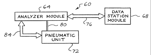
Figure 1 is a block diagram of a cell analysis system 60. The system 60
includes an analyzer module 64, a data statiommodule 68, and a pneumatic unit
72. The
analyzer module 64 is operatively connected to the data station module 68 by a
serial data
link 76 implementing a HDLC (high level data link) protocol. The pneumatic
unit 72 is
operatively connected to the analyzer module 64 by a serial data link 84 and a
network of
tubing 80.
The analyzer module 64 aspirates samples, diluent and reagents, dilutes
samples, measures and collects data, transmits measured data to the data
station module
68, manages reagents, and disposes of waste. An exemplary analyzer module 64
includes
its own power supply, impedance transducer, HGB transducer, optical
flowcell/transducer (light scattering and fluorescence), optical detectors,
electronics,
reagent reservoirs, fluidics system, integrated and fully automated sample
processor for
both hematology and fluorescent cytometry tests, and any necessary incubation
and/or
cooling systems. An exemplary analyzer module includes a Motorola 68302TM-type
microcomputer that controls mechanical components of the analyzer 64 and
executes the
analyzer's flow sequences.
The pneumatic unit 72 houses pneumatic sources for moving fluids through
the analyzer module 64. The pneumatic unit 72 receives instructions from the
analyzer
module 64 via that serial data link 84.
CA 02258603 2003-02-05
24
The data station module 68 provides general controls to the analyzer module
64, converts measured data into meaningful test results, stores measured data
and test
results, prints reports, and provides bi-directional communication with an off
line host
computer (not shown). An exemplary data station module 68 includes an 80386 or
80486-type microcomputer, color display, 3 1/2 inch disk drive, at least 540
megabyte
hard disk, PC-style keyboard, a pointing device, and LAN connections. The data
station
68 includes memory, such as a RAM, a.ROM, an EPROM, a SRAM and the, like,
having sufficient software algorithms to manipulate measured data, calculate
parameters, and display results in a variety of formats, including histograms,
scattergrams, and other multidimensional plots.
2. Fast Lvse Multipurpose Reagent System
The cell analysis system 60 utilizes a multipurpose reagent system suitable
for the rapid analysis of nucleated peripheral blood cells, including white
blood cells
("WBC") and nucleated red blood cells ("NRBC"). The multipurpose reagent
system
can substantially completely and rapidly lyse red blood cells, while
concurrently
substantially preserving white cell morphology and the antigenicity of
lymphocyte
surface antigens.
The multipurpose reagent system is fully described in U.S. patent 5,516,695
entitled "Multipurpose Reagent System For Rapid Lysis of Whole Blood Samples",
filed August 29; 1994.
One embodiment of the multipurpose reagent system comprises from about
3 to about 7 grams per liter of a non-quaternary ammonium salt, from about
0.04 to
about 0.1 % by weight volume (i.e., grams per 100 ml) of an aliphatic
CA 02258603 1998-12-16
WO 98/02727 PCT/LTS97/11105
aldehyde with one to four carbons, from about 10 to about 20
mM of a non-phosphate buffer which is substantially inert to
the aliphatic aldehyde, and water. The pH of the reagent
system is within a pH range of about 5.5 to about 7.5 and the
5 osmolality of the reagent system is between about 160 to 310
(mOsm/L). The refractive index of the reagent system can be
similar to that of saline and should preferably be within the
range of about 1.333 to about 1.336. The non-phosphate
buffer is inert to the aliphatic aldehyde in that the non-
10 phosphate buffer will not react with the aliphatic aldehyde.
Thus, generally, the non-phosphate buffer should not contain
a primary amino group.
Another embodiment of the multipurpose reagent system
comprises about 135 mm ammonium chloride, about 0.075 by
15 volume of formaldehyde, about 20 mM acetate buffer, about 10
mM potassium bicarbonate, and about 0.01 by weight volume
(i.e., grams per 100 ml) of saponin and the like. The pH of
the reagent system is adjusted to about pH 6.2 and the
osmolality of the reagent system is from about 267 to 270
20 mOsm/L.
The multipurpose reagent system is utilized in the
automated determination of differential white cell patient
counts, nucleated red blood cells, and lymphocyte
immunophenotyping. A method for the rapid analysis of
25 nucleated peripheral whole blood cells includes the following
steps: mixing the described multipurpose reagent system with
an anticoagulated whole blood sample (whereby the blood is
diluted 10 to 100 fold), mixing the diluent-blood mixture at
temperatures from about 25°C to 46°C for at least about 10
seconds, and analyzing the nucleated peripheral blood cells
with the automated cell analysis system ofthe present
invention.
A method of using the multipurpose reagent system in the
differential analysis of peripheral white blood cells is a
rapid, one-reagent method of concurrently lysing red blood
CA 02258603 1998-12-16
WO 98/02727 PCT/LTS97/11105
26
cells and fixing white blood cells, wherein the white cells
maintain their light scattering characteristics. In general,
the cells flow through an optical view chamber where a
photoelectric measuring process records the light absorbed or
type of light scattered by each cell at selected angles.
A first ingredient of the multipurpose reagent system is
a non-quaternary ammonium salt. Preferably, neither di- nor
tri-ammonium salts should be used. A variety of mono-
ammonium salts, particularly the halogenated salts, can be
20 used from about three to about seven grams per liter, and
preferably at about 5 grams per liter_ Examples of such non-
quaternary ammonium salts include NHQX, where X is a halogen.
Such a non-quaternary ammonium salt is NH4C1.
A second ingredient of the multipurpose reagent system
- is a short-chain aliphatic aldehyde. Preferably, such
aliphatic aldehydes have from one to four carbons. Exemplary
aldehydes include formaldehyde and the polymer
paraformaldehyde. In proper ratios and concentrations, the
aldehyde, in conjunction with the non-quaternary mono-
ammonium salt, and the buffer, will rapidly and substantially
completely lyse red blood cells. Ln addition, the aldehyde
will fix white blood cells and substantially preserve their
membrane integrity. Formaldehyde, or comparable aldehyde, is
present in amounts from about 0.045 to about 0.100 by volume,
= and preferably from about 0.08 to about 0.1~ by volume.
A third ingredient of the multipurpose reagent system is
a non-phosphate buffer that is substantially inert to the
aldehyde component of the reagent system. Thus, the buffer
must not contain a primary amino group_ The buffer should
also have an effective buffering capacity between pH of about
6.0 to about 7.5, and an Osmolarity of about 230 to about 310
mOsm/L. Examples of effective organic buffers are acetate
buffer, succinate buffer, maleate buffer, and citrate buffer.
Examples of effective biologic buffers are 2-(N-morpholine)
CA 02258603 1998-12-16
WO 98/02727 PCT/US97/11105
27
ethane sulfonic acid (MES) buffer, 3-(N-marpholine) propane
sulfonic acid (MOPS) buffer, and N-(2-hydroxyethyl)
piperazine-N'-(2-ethane sulfonic acid) HEPES buffer. An
acetate, or other suitable buffer, will be present in amounts
from about 10 mM to about 20 mM concentrations, and
preferably at about 20 mM concentration,
An optional component of the multipurpose blood diluent
is a surface active reagent. The preferred surface active
agent is saponin, a plant extract that is available in a
commercial grade powder isolated from quillaja tree bark as
well as other sources. Although the chemical purity of
commercial saponin varies from lot to lot, it is more
selective towards red cells than are the quaternary ammonium
salts. Saponin, or other surface active reagent, is present
in amounts from about 10 to about 200 mg/L, and preferably at
about 100 mg/L. Saponin, in concert with the other
ingredients of the multipurpose reagent system, substantially
completely lyses the red blood cells present in whole blood.
The erythrocyte fraction (i.e. red blood cells) of
normal blood samples will normally be lysed within about 20
seconds at ambient temperatures. However, hard-to-lyse blood
samples (such as blood samples from babies, kidney dialysis
patients, multiple myloma patients, diabetics, or patients
with uremia, for example) require incubating the blood with
the reagent system at temperatures of about 38°C to about
40°C for up to about 20 seconds for complete erythrocyte
lysis. Incubation of blood samples with the multipurpose
reagent system, even at these slightly elevated temperatures,
effectively preserves white cell membrane integrity and
retains the antigenicity of lymphocyte surface antigens. In
contrast, if saponin is used by itself to lyre the red cells,
it should be used at a concentration about 10 to 20 times
- higher than those discussed above. . Such concentrations may
compromise the integrity of the white cells and require a
rapid quenching of the iytic activity of the reagent to
CA 02258603 1998-12-16
WO 98/02727 PCT/US97/I1105
28
preserve white cell morphology. An advantage of the
embodiments of this reagent system is that the combined
constituents of the multipurpose reagent system serve to "
gently fix the white cells at the same time that the red
cells are being lysed. Therefore, white cell integrity is
substantially preserved even at relatively long incubation
periods_ In fact, even fragile white cells, such as those
seen in chronic lymphocytic leukemia patients, are stabilized
in the multipurpose reagent system for incubation periods of
up to about 20 minutes.
An additional, optional ingredient of the multipurpose
reagent system is an alkali salt, preferably a monovalent
alkali salt of bicarbonate. Although a monovalent alkali
salt of bicarbonate is not an essential component of the
- diluent, it may be added to the diluent to raise its
osmolality without reducing the red cell lysability of the
reagent system. Many other compounds, such as sodium
chloride, potassium chloride or phosphate buffer, diminish
the lysability of the reagent system when used to increase
the osmolality of the reagent system. Exemplary monovalent
alkali salts of bicarbonate are potassium bicarbonate, sodium
bicarbonate, lithium bicarbonate and the like. Potassium
bicarbonate, or other alkali bicarbonate salt, can be present
in amounts from about 0.0050 to about 0.015 by weight
volume, and preferably at about 0.01% by weight volume.
Yet another optional ingredient of the multipurpose
reagent system is a platelet anti-clumping agent. For
example, an ethylenediaminetetraacetate (EDTA) salt can be
added to the reagent system to reduce platelet aggregation in
- the sample/reagent mixture. Tetrasodium EDTA, or other EDTA
salt, is present in amounts from about 20 to about 200 mgs
per liter and preferably at about 100 mgs per liter.
A further embodiment of the multipurpose reagent system
allows for the quantitative analysis of lymphocyte
subpopulations. Lymphocyte subclassification is achieved by
CA 02258603 2003-02-05
29
mixing fluorochrome-conjugated monoclonal antibodies (directed to specific
lymphocyte
surface antigens) with whole blood samples before adding the multipurpose
reagent
system, or blood diluent. The concentration of labeled antibody fractions
added to a
blood sample depends upon the individual antibody preparation, but is commonly
about
one-half to onetenth of the volume of the blood for commercial antibody
preparations.
After the reagent system is added and the red cells are lysed, the lymphocyte-
antibody
reaction products can be analyzed on an automated flow cytometric system.
There is no
need to "separate" the lymphocytes from the lysed cells by centrifugation and
washing as
is common in the art.
The disclosed reagent system does not "quench" fluorescent markers, such as
fluorescein isothiocyanate (FITC) or phycoerythrin (PE), which are used to
fluorochromelabel antibodies. Lymphocyte subclassification is a diagnostic
tool in the
fight against many diseases, such as AIDS. The ability to identify surface
markers on
blood cell populations may be important when coupled with knowledge of surface
components and characteristics of subpopulations of lymphocytes and other
white cell
fractions such as monocytes and neutrophils.
3. Nucleated Red Blood Cell Differentiation and Reagent
The cell analysis system 60 utilizes an automated method for simultaneous
analysis of WBC/Diff and NRBC in a whole blood sample using a unique triple
triggering method with lyse reagent, such as the rapid lyse reagent system
described
above. This method, claimed in U.S. Patent 5,559,037, entitled "Method For
Rapid And
Simultaneous Analysis Of Nucleated Red Blood Cells", enables the accurate NRBC
counts and WBC/Diff data, simultaneously from a whole blood sample
CA 02258603 2003-02-05
containing NRBC.
An important aspect of the NRBC method is that the signals from debris
(both fluorescent and non-fluorescent) are blocked by the triple triggering
method and
the signals which fall below the ALL trigger but above the FL3 trigger can be
identified
and counted as NRBC. Therefore, accurate NRBC counts, which are essentially
free of
contamination from fluorescent nuclear debris, are obtained. Fragile blast
cells and
dead cells (non-viable) may also be detected utilizing the methods of this
invention.
In the triple trigger method, it is possible to simultaneously count WBC/Diff
and NRBC accurately by mixing the blood sample with a blood diluent which
rapidly
lyses RBC and preserves WBC, and to which has been added a suitable nuclear
stain
which will stain naked nuclei of the NRBC. Such a diluent is disclosed above.
The
diluent/sample mixture is then passed, essentially a cell at a time through an
illuminated
optical flow cell. This causes the cells to scatter the illuminating light and
any stained
nuclei present to fluoresce. The scattered and fluorescent light signals are
detected by
known means and, by using the triple triggering method in conjunction with the
processing of the detected signals it is possible to identify and quantify
WBC,
WBC/Diff and NRBC.
The triple trigger method is unique in that the simultaneous analysis of
WBC/Diff/NRBC can be carried out automatically, accurately, and rapidly
without
interference from other cellular debris such as RNA from lysed reticulocytes,
Howell
Jolly Bodies, reticulated platelets, giant platelets, DNA from WBC and
Megakaryocytic
fragments, parasites, and RBC fragments.
The triple trigger method also permits accurate WBC/Diff analysis in a
blood sample that contains NRBC by subtracting signals identified as NRBC from
she
total WBC signals before
CA 02258603 1998-12-16
WO 98102727 PCT/US97/11105
31
WBC/Diff analysis is performed. only one dye is needed for
NRBC staining and the WBC/Diff analysis can be performed by
the difference of light scattering characteristics of the WBC
subclasses.
The NRBC method achieves all of the objectives described
above by a unique triple triggering method in the three
dimensional space of Axial Light Loss (ALL), Intermediate
Angle Scatter (IAS) and Red Fluorescence (FL3)._ _
To accomplish this, one or more detectors 380 (Figures
19, 20 and 21) are preferably placed in the forward light
path for measuring forward intermediate angle scattering
(IAS) 384 and either small angle forward scattering (SAS) or
axial light loss (ALL, also known as forward extinction) 382.
ALL is generally the decrease in light energy due to a
cell passing in front of a laser beam and being detected by a
photodiode. The light loss is generally due to scattering
and defined as the decrease in light energy reaching a
detector in the path of a laser beam due to the passage of a
cell through that beam (generally ALL is detected at an angle
of from about 0~ to about 1«.) Small angle forward scatter
(SAS), in contrast, is light energy that reachesa detector
outside (but within a narrow angle of about 1o to 3~) the
incident laser beam due to scattering from a cell passing
through the beam. A beam stop is generally provided to keep
the laser beam from getting into the detector. ALL measuring
systems collect light within the incident cone of laser
illumination, while small angle scatter systems collect light
outside this cone. In ALL measuring systems, the signal of
interest is a negative signal subtracted from the steady
state laser signal, whereas in small angle forward scatter
measurement the signal is a small positive signal imposed on
a very low background light level. Intermediate angle
forward scattering (IAS) is similar to small angle forward
scattering, except the light is scattered at a larger angle
from the incident laser beam. More specifically, IAS relates
CA 02258603 1998-12-16
WO 98/02727 PCT/US97/11105
32
to light scattered in a ring between about 3~ and 10~ away
from the incident or center line of a laser beam. In a
preferred embodiment, ALL is collected in the angles less
than about 0.3~ horizontally and less than about 1.2~
vertically from the laser axis, and IAS is collected at
angles between about 3« and 10n from the laser axis.
Another technical advantage of the disclosed system is
that it requires much lower concentration of the dye to
effectively and rapidly stain NRBC for accurate detection and
counting because of complete lysis of the cytoplasm of NRBC
making their nuclei more accessible to the stain. This
condition permits high signal to noise (S/N) ratio, greater
than 100, in NRBC detection. The concentration of a vital
dye required this system to rapidly perform the-simultaneous
analysis of WBC/Diff/NRBC is only 1 to 2 ~.~.g/ml which is at
least 50 fold less than that in the previous art.
Vital stains (nuclear stains which stain only dead or
damaged cells) that can be used in the present invention can
be any vital stain with relatively high extinction
coefficient and low fluorescence intensity when they are not
bound to nucleic acid. The spectral characteristics, i.e.
Extinction (EX) max. (nm) /Emission (EM) max. (nm) , of the
vital dyes must be compatible with the laser light source
used in the system.
The following characteristics are desired for the vital
stains for the disclosed system:
High extinction coefficient
High quantum yield
High binding affinity to nucleic acid
- Low fluorescence when it is not bound to nucleic
ac id ~ '
Light source compatibility of Spectral Characteristics.
(e.g. EX max.--488 nm and EM max. -- 630 nm with an Argon .
laser light source.)
CA 02258603 2003-02-05
33
There are a number of nuclear dyes qualified for use in the disclosed
system with appropriate light source. some of the commercially available dyes
that can
be used in the disclosed system are YOYO-1, YOYO-3, TOTO-l, TOTO-3, BO-PRO-
1, YO-PRO-1, TO-PRO-1 (all trade-marks), and many more. It is known to those
who
are familiar in the art that the dyes with different EX max. can be excited
with
appropriate light source such as He-Ne, Xenon or Mercury lamps.
Qualified dyes which can be used with an Argon laser which are also
commercially available are Propidium iodide (PI), ethidium bromide (EBr),
ethidium
homodimer-1 (EthD-1), ethidium homodimer-2 (EthD-2) or diethylene triamine
(DTA).
In one application of the NRBC method, the vital stain used is PI.
A portion of a whole blood sample, about 25 microliters, is deposited by
means of a sample aspiration probe into the WBC cup 138 (Fig. 5) which
contains
about 850 microliters of an isotonic lysing reagent. A lysing reagent
described above
is used to lyse the erythrocyte fraction of the blood sample and to lyse the
cytoplasm
of NRBC to expose the nuclei of any NRBC present. This reagent system is
characterized in that it embodies a one reagent/one step process that achieves
multipurpose goals. This reagent is gentle enough to preserve the morphology
of all
fragile white cells, and at the same time efficiently lyse all of the red
cells. Both of
these goals are accomplished even in hemaglobinophathic samples, which may
require
that the lysing time be extended.
No matter what the formulation of the lyse utilized with the triple trigger
method, the reagent will additionally contain, or be combined with, a small
concentration of a vital nuclear stain which effectively labels any NRBC which
might
be present in the peripheral blood. Preferably, for use with the herein
referenced
analyzer, the lysis chemistry will be configured such that the refractive
index matches
that of a sheath solution to substantially less than 0.1 %.
CA 02258603 2003-02-05
34
The mixture of lyse reagent and sample will normally remain in the WBC
cup 138 (Fig. 5) only for about 11 seconds. There it is lysed and mixed at
42°C t 3°C.
At this point, the contents of the WBC cup are piped directly to an optical
flowcell 170
(Fig. 5) for detection.
The measurement process begins as the cells stream passes through the
flowcell 170, having been diluted with the addition of lyse so that the cells
pass
through the laser illuminated volume single file, in a laminar flowing sample
stream
surrounded by diluent/sheath solution.
At this point the presence of a cell is detected by 'a compound photodiode
380 detecting axial light loss (ALL) and intermediate angle scatter (IAS),
photomultiplier tube which detects red fluorescence, and a unique triple
trigger circuit,
shown in Figure 2, in the three dimensional feature space of ALL, IAS, and FL3
(red
fluorescence). The triple trigger circuit qualifies signals for digitization
using
AND/OR logic. A qualified signal must be greater than the IAS trigger, while
at the
same time it must be greater than either the ALL trigger or the FL3 trigger.
The
combination of this unique triggering circuit, and the lysing properties which
include a
balanced fixative, allow the exposed NRBC nuclei to be rapidly stained, and
clearly
and non ambiguously counted and excluded from the WBC differential cell count
without the usual interference from background, both fluorescent and non-
fluorescent,
such as DNA fragments, RBC' stroma, and platelets.
When cells, thus triggered, pass through the aforementioned illuminated
volume, pulses are generated at detectors 380, 400, 401 and 404 (Figs. 19 and
20). The
amplitudes of these pulses are then filtered, amplified, digitized, and stored
in list
mode in the corresponding five dimensional feature space of ALL, IAS, FL3, PSS
(polarized side scatter), and DSS (depolarized side scatter). The normal
counting time
through flowcell 170 (Fig. 5) is 10 seconds. At the flow rate and dilution
CA 02258603 1998-12-16
WO 98/02727 PCT/US97/11105
ratio described above,
with a normal patient
WBC count of
7000 cells per microliter of blood volume, the resulting
event count rate would 5000. In low count samples, this
be
counting time can be auto matically extended in order to
5 improve the statistics the measurement. At the conclusion
of
of the measurement time, the sample stream is piped to waste,
and probe is cleaned and driedand prepared to process a
subsequent sample.
Algorithms are then applied to the list mode data of
the
10 aforementioned feature
space of ALL, IAS, FL3,
PSS, and DSS,
and the following cell
types are enumerated and/or
flagged
within less than 30 seconds
of processing time:
CRT_,L TYPES ENUMERATED PERCENTAGES FLAGGED OR
15 ENUMERATED
White Cell concentration (WBC)
Neutrophil concentration aN of WBC
Lymphocyte concentration oLYMPH of WBC
Monocyte concentration oMONO of WBC
20 Eosinophil concentration o EOS of WBC
Basophil concentration ~BASO of WBC
NRBC oNRBC of WBC
Band concentration (BAND)
Blast concentration (BLST)
25 Immature Bran. conc. (IG)
Variant-lymph cone. (VARL)
ALL and IAS signals are detected and collected for the
WBC/Diff analysis and FL3 signals from stained NRBC nuclei
30 are collected for NRBC analysis, as will be described below.
The triple trigger circuit, shown in Figure 42, qualifies
these signals for digitization using AND/OR logic. To be
qualified a signal must be greater than the IAS trigger,
while at the same time it must be greater than either the ALL
35 trigger or the FL3 trigger.
CA 02258603 1998-12-16
WO 98/02727 3'CT/LTS97/I1105
36
The various components and generated or utilized
signals identified in Figure 42 correspond to the following
labels:
900 - ALL Voltage Comparator
902 - ALL Signal
904 - ALL Threshold Voltage (Vth1)
906 - ALL Voltage Comparator Output
910 - FL3 Signal
912 - FL3 Threshold voltage (Vth2)
914 - FL3 Voltage Comparator
916 - Voltage Comparator Output
FL3
918 - Signal
IAS
920 - Threshold Voltage (Vth3)
IAS
922 - Voltage Comparator
IAS
924 - Voltage Comparatar Output
IAS
926 - Gate
OR
928 - Gate Output
OR
930 - Gate
AND
932 - id Trigger Output
Val
Real time signals from their respective channels are
present at the inputs of the voltage comparators. Voltage
comparators.900, 914 and 922 function by comparing the "+
inputs" (902, 910 and 918) to the "- inputs" (904, 912 and
920) to resultant outputs (906, 916, 924). If the "+ input"
is of a higher voltage than the "- input" the output will be
high. If the "+ input" is of a lower voltage than the "-
input" the output will be low.
The threshold voltages are independent voltages which
are determined by system parameters.
The outputs of comparators 900 and 914 are inputs to OR
gate 926 to give resultant OR gate output 928. The OR gate
functions by comparing its inputs. The output will be high
if either, or both, inputs are high.
CA 02258603 1998-12-16
WO 98/02727 PCT/US97/11105
37
The output of the OR gate 928 and the output of
comparators 922 and 924 are inputs to AND gate 930_ The AND
gate functions by comparing its inputs to derive its output
_ 932 which is also the valid trigger output. The output will
be high only if both inputs are high.
The valid trigger output 932 will only be high if the
IAS signal 918 is greater than its threshold voltage 920, and
either or both, the ALL signal 902 is greater than its
threshold voltage 904 or the FL3 signal 910 is greater,than
its threshold voltage 912_
Using the above triggering circuit, the NRBC's form a
unique cluster in the aforementioned three dimensional space,
see Figures 40A-C and 41A-B, which can be easily counted
during the Optical WBC Differential analysis, and exclude
non-ambiguously from the WBC count. Thus, a count of NRBC
per 100 WBC, and an absolute NRBC per ~1 of patient blood is
reported. Consequently, NRBC are subtracted from total WBC
counts permitting accurate total wBC and Differential
analysis in the presence of NRBC in a blood sample.
Background noise, both fluorescent and non-fluorescent, from
DNA fragments, RBC stroma, platelets, f~owell-~7olly Bodies,
Basophilic Stippling, RNA from lysed reticulocytes and DNA
from WBC and Megakaryocytic fragments are substantially
eliminated. Stained NRBC nuclei are separated from the
various background noise signals via the disclosed triple-
triggering process (on ALL, IAS and FL3) and only the FL3+
signals from NRBC nuclei above the FL3 trigger_on the ALL vs.
FL3 dot plot are counted as NRBC (Figures 40A-C and 41A-B).
~ RPr; n"1 nc-vt-e Method and Reaaent
f
In one aspect of the cell analysis system 60 a stable,
aqueous reagent composition is utilized for the detection and
enumeration of reticulocytes. This reagent comprises: an
unsymmetrical cyanine dye capable of staining reticulocytes,
CA 02258603 1999-OS-14
WO 98/02727 PCT/LTS97/11105
38
from about 20 mM to about 50 mM of a buffer selected from the
group consisting of Imidazole buffer,
4-(2-Hydroxyethyl)-1-peperazineethane-sulfonic acid ("Hepes")
buffer, Bis (2-Hydroxyethyl)-1-piperazineethane-sulfonic acid
("Bis-Tris") buffer and Tris Hydroxymethyl Aminomethane
("Tris") buffer; a pH from about 6.0 to about 8.0; an
osmolarity adjusted to about 230 to about 340 mOsm/L with a
mono, or di, valent alkali salt;-and a non-ionic surfactant
(from about 5 mg/dl to about 1.0 g/dl depending on the
surfactant) which facilitates the membrane permeation and
stabilizes the cyanine dyes in an aqueous isotonic solution.
Preferably the dyes are cyclic subsr_itiited and exhibit
enhanced fluorescence upon binding with DNA or RNA. Even
more preferably, the reagent comprises from about 0.1 ~tg/ml
to about 0.3 ~tg/ml of a cyclic substituted, unsymmetrical
cyanine dye.
The methods for the rapid and continuous detection and
enumeration of reticulocytes and CBC differentials,~utilizing
the present inventive reagent system. Such methods are
distinct due to the particular absence of the need to provide
for a separate incubation step. The minimal, 10 to 60 second
incubation period is all that is necessary.
The disclosed method and reagent are the subject
of Canadian Patent Application Serial Number 2,218,728,
entitled "Composition and Method for the Rapid Analysis
of Reticulocytes", filed on April 19, 1996, Abbott
Laboratories.
The method allows the enumeration of reticulocytes from
a whole blood sample while simultaneously differentiating a
separate aliquot of the sample to obtain a complete blood
cell !"CBC") analysis. This method comprises, directing one
or more aliquots of the sample to vario,is positions within an
automated analyzer for analysis and differentiation, while a
i
CA 02258603 2003-02-05
39
reticulocyte aliquot of the sample is combined with a staining reagent.
The combined reagent/reticulocyte aliquot is then directed to an optical flow
cell
170 (Fig. 5) of the automated analyzer 60 (Fig. 1 ). Thereafter the
reagent/reticulocyte
aliquot is passed through an illuminated sensing zone 300 essentially one cell
at a time to
cause fluorescence and scattered light events. These events are detected and
the number
of reticulocytes present in said sample are determined therefrom.
The unsymmetrical dyes usable with the reagent system generally have the
following characteristics:
1. Absorption Maxima : 488 +20 nm
2. High nucleic acid binding affinity
3. High quantum yield : >_0.1
4. Molar Extinction Coefficient: >_10,000
5. Fluorescence Enhancement upon binding to RNA or DNA: >_20
6. Membrane Permeation Rate: <2 minutes
Typically, the dyes utilized in the disclosed aqueous reagent and reticulocyte
enumerating methods are highly unstable in aqueous environments. However the
disclosed reagent formulation provides extended stability and shelflife to the
finished
reagent.
A preferred embodiment of the reagent system comprises from about 0.05
~.ilml to about 0.5 l.~lml of Sybr 1 l, a proprietary dye sold by molecular
Probes, Inc.
(Eugene, OR), from about 20 mm to about 50 mM Imidazole buffer, and from about
5
mg/dl to about 20 mg/dl of N,N-bis(3-D-Glucon-amidopropyl]cholamide
("BIGCHAP"),
from about 0.02 % to about 0.05 5 % Proclin~ 300 (5-chloro-2-methyl-4-
isothiazoline-3-
one + 2-methyl-4-isothiazoline-3-one). The pH is adjusted to from
CA 02258603 2003-02-05
about 6.8 to about 7.2 with 1N HC1 and the Osmolarity adjusted with NaCI from
about
270 to about 310 mosm/L.
A main ingredient of the reagent system is the dye. One such class of dyes
are unsymmetrical cyanine dyes such as those disclosed in W094/24213, "CYCLIC-
SUBSTITUTED UNSYMMETRIC DYES". Additionally, the dyes utilized in this
invention exhibit enhanced fluorescence upon binding with DNA or RNA. Such
useful
dyes must also have high binding affinity to RNA and DNA and a high quantum
yield.
It is anticipated that a variety of unsymmetrical cyanine dyes which exhibit
the characteristics described and claimed herein can be used. Some of the
examples of
such dyes include, but are not limited to Sybr 11, Sybr 14, Sybr 16 (all
trademarks),
obtained from Molecular Probes, Inc. (Eugene, OR) ("MPI"). Other unsymmetrical
cyanine dyes such as Syto 12, also sourced from MPI, are also useful in
practicing the
present invention. Syto 12 is believed to be a neutral, unsymmetrical cyanine
dye
comprising a substituted benzazolium ring system linked to a methine bridge to
a
pyridinic or quinoline ~ing system.
A further ingredient of the reagent system is a buffer whose pKa is from
about 6.0 to about 8.0 and is capable of maintaining the required (for
staining RNA or
DNA) concentration of the cyanine dye in an aqueous solution in an extended
period of
time. Such buffers should not react with the cyanine dyes or the non-ionic
surfactants
used in the practice of this invention to stabilize the dye. Exemplary buffers
include
Imidazole, Hepes, Bis-iris, and Tris.
Another ingredient of the reagent system is a non-ionic surfactant. Depending
upon the surfactant, or combination of non-ionic surfactants, that are use,
the
concentration should be fi~om about 5 mg/dl to about 1 g/dl. The surfactants)
appear to
enhance the rate of the cyanine dye permeation through the cell membrane
(within 30
seconds). In addition, the solubility and the stability of the cyanine dyes in
an
CA 02258603 1998-12-16
WO 98/02727 PCT/LTS97J11105
41
isotonic aqueous solution are enhanced by the surfactant.
Such surfactants) should not, however, precipitate or react
with the cyanine dyes or lyse RBCs, even at the low
concentrations. Examples of such surfactants are, but are
not limited to, BIGCHAP, n-Dodecyl-D-Maltoside, .
Polyoxypropylene-polyoxyethylene block copolymer ("Pluronic~
F127°), n-Tetradecyl-D-Maltoside,
Decanoyl-N-methyl-glucamide, n-Dodecyl-D-glucopyranoside and
n-Decyl-D-glucopyranoside.
Yet another ingredient of the reagent system is a mono-,
or di-, valent alkali salt to adjust the osmolarity of the
reagent from about 230 mOsm/L to about 340 mosm/L to prevent
the lysis of red cells, including the reticulocytes, or the
white cells. Such salts should not react with the either the
cyanine dyes or precipitate in solution. Examples of such
salts include NaCl, KC1, LiCl, CaClz, MgCl~, ZnCl~ and others.
An optional ingredient, is a preservative to prevent
microbial growth in the reagent. Such a preservative should
not change the light scattering or fluorescent emission
properties of the cells, or stained cells. Examples of such
preservatives include Proclin~ 300, Proclin~ 150, sodium
azide and others.
Generally, however, a method for practicing the present
invention comprises the mixing of a whole blood sample with a
reagent to stain the RNA of any reticulocytes present,
flowing the mixture, essentially one cell at a time, through
an illuminated optical flow cell, detecting the light
scattered and fluorescence emitted therefrom and determining
the amount of reticulocytes present in the sample without
subjecting the sampie/reagent mixture to a separate
incubation step or period.
In order to analyze a whole blood sample for the
- percentage as well as the absolute counts of reticulocytes on
the mufti-parameter hematology analyzer described above,
CA 02258603 2003-02-05
42
about 18.75 gl of a whole blood sample is deposited by means of a sample
aspiration
probe into the RBC cup 134 (Fig. 5) which contains about 7856 pl of a
diluent/sheath
solution (an isotonic saline) and the fluids are mixed. The diluted sample is
then
transported to a sheathed impedance aperture 174 to electronically determine
the absolute
RBC counts of the sample. In the meantime, about 200 p,l of the diluted sample
is
transferred into Retic cup 136 (Fig. 5) which contains 600 ~l of the disclosed
reagent,
where it is mixed. The prepared (mixed) sample is then transported to the
sheathed
optical flow cell 170 (Fig. 5) for detection. The measurement process begins
as the cell
stream passes through the flow cell essentially one cell at a time, in a
laminar flowing
sample stream surrounded by a diluent-sheath solution, disclosed hereinafter.
At this point, and as shown in the two dimensional feature space of IAS and
FLl of the cytogram of Figures 14A and B, the presence of a cell is detected
by an
intermediate angle scatter photo-diode 380 which detects light in a 3~ to
10° cone, and a
photomultiplier tube ("PMT") 400 which detects green fluorescence, FL1. when
cells
pass through the aforementioned illuminated volume, pulses are generated and
measured
by these detectors. 'The amplitudes of these pulses are then filtered,
amplified, digitized,
and stored in list mode in the corresponding two dimensional feature space of
IAS and
FL1. The cells are counted for 8 seconds. At the flow rate and the dilution
ratio described
above, with a normal subject RBC counts of 5 millions per microliter of blood
volume,
the resulting event count rate would be 5950 per second. Algorithms are then
applied to
the list mode data of the aforementioned feature space of IAS and FL 1 and the
following
parameters are measured within 20 seconds of computational time:
CA 02258603 1998-12-16
WO 98/02727 PCT/US97111105
43
1. RBC gate: WBCs and platelets are excluded by gating
the RBC population, inc hiding reticulocytes, but excluding
WBCs and platelets.
2. The percent of reticulocytes: The gated RBC
population is reanalyzed according to the size of their FL1
signals. A log fit is applied to the FLl histogram to define
the region which belongs to mature RBCs, and the cells whose
FL1 signals fall above the region are labeled as
reticulocytes. Reticuiocyte ~ is computed by dividing the
counts of reticulocytes by the total RBC counts.
3. The absolute reticulocyte counts: Obtained by
multiplying the percent of reticulocytes by absolute RBC
counts of the sample from the CBC mode.
4. Reticulocyte Maturity Index ("RMI"?: RMI is
expressed as the percent of reticulocytes whose FL1 signals
are more than one (1) standard deviation ("S.D.") above the
mean fluorescence of a normal reticulocyte population.
Such a description is rnerely for convenience and by no
means is the expression of RMI of the present invention
limited to only the algorithms discussed herein.
A~rArnarA ReticulQCVte Stain & Analysis
The disclosed alternate class of reticulocyte stains is
stable to light at ambient temperature, possesses improved
fluorescence enhancement of the bound stain over the unbound
stain, exhibits RNA selectivity over DNA, enables improved
gating of the reticulocyte cells, provides more rapid
permeation of cell membranes, and possesses an optical
absorption maximum closely aligned with the emission maximum
' of an argon laser (about 488nm).
CA 02258603 1998-12-16
WO 98/02727 PCT/US97/11105
44
13 preferred stain belongs to a class of molecules having
the general structural formula:
R2
R3 ~ I x~-(CH=CH}~ CH
R
4
R1
wherein:
x = O, S, Se, or C(CH-~)z2
R1 = alkyl having from 1-6 carbons
Rz = alkyl having from 1-6 carbons
R3 = fused benzene, alkyl (having 1-6 carbons) methoxy or
hydrogen
Rq = alkyl having 1-6 carbons, methoxy or hydrogen
n = zero or an integer from 1-6
This class of stains will be referred to herein as
_ "2,2'-dyes."
The preferred embodiment of the reticulocyte stain shown
above is where:
Preferably, x is sulphur (S)
Preferably, R~ and R4 are both hydrogen
Preferably, n = O and
Preferably, R1 and R~ are both ethyl.
This dye is listed in the Koch-light Biochemical
Catalogue 1985, and 1988/89 at page 53 in the form of an
iodide salt, and named 1,3'-diethyl-2,2'-quinolylthiacyanine
iodide. It is also listed in the Nippon Kankoh-Shikiso
Kenkyusho catalogue at page 7. For convenience hereinafter,
we shall refer to this specific dye, the particularly
CA 02258603 1998-12-16
WO 98102727 PCT/US97/11105
preferred embodiment, as "DE22QTC", and to the general r_lass
of dyes, as defined above, as "2,2'-dyes".
Generally, these dyes are used in the form of their
salts, iodides being particularly convenient. As used in
- 5 this specification, all references to these dyes should be
understood as including such. dyes in salt form.
In one embodiment a reagent useful for staining RNA-
containing material which is comprised of.a 2,2'-dye which is
capable of staining RNA-containing material.
10 Another embodiment a method for staining RNA-containing
material wherein an aqueous staining solution of a 2,2'-dye
which is capable of staining RNA-containing material is
placed in contact with an RNA-containing material for a
period of time adequate to enable the staining solution dye
15 to penetrate the RNA-containing material.
Another embodiment provides a method for enumeration of
reticulocytes in a whole blood sample using flow cytometry
wherein an aqueous staining solution of a 2,2'-dye which is
capable of staining RNA-containing material is placed in
20 contact with an RNA-containing material for a period of time
adequate to enable the staining solution dye equilibrate with
the RNA-containing material. The stained sample is then
directed through the optical sensing zone of a flow cytometry
instrument and illuminated once within the optical sensing
25 zone with an incident light beam. The fluorescence of the
reticulocytes in sample solution are then measured as they
pass through the optical sensing zone.
An important advantage of the 2,2'-dyes is that they
appear to be more stable in aqueous solution than thiazole
30 orange. This has been examined using samples of DE22QTC,
thiazole orange (both at 0.1~.t.g/ml in isotonic diluent) and
"Retie-COUNT" stored both at 4°C in the dark and in room
light at ambient temperature (about 25°C) over a period of 5
days .
CA 02258603 1998-12-16
WO 98/02727 1'CT/gJS97/11105
46
The 2,2'-dyes exhibit a significantly greater
fluorescence when RNA rather than DNA is the binding
substance, on a weight-for-weight basis DE22QTC allows easy
gating of_red blood cells away from platelets and white cells
using a strategy not previously adopted for reticulocyte
analysis. The dye, by its significant staining of platelets
over the 30 minute period of a typical test and its expected
staining of white cells in the same period, provides
significant differentiation of both groups of cells from all
the red cells in a plot of fluorescence versus forward
scatter. The rapid staining is a property not shown by many
other dyes; e.g. thiazole orange does not stain platelets
significantly over the 30 minute time period although after
several hours, staining does occur.
DE22QTC, when bound to RNA or DN1.~, has an absorption
maximum of almost precisely 488nm, and a Stokes shift of
about 33nm. This dye therefore can be used with maximum
advantage with the standard argon ion laser.- Moreover, the
readily-available optical filters used for fluorescein-based
assays can be used and the instrument need not be modified.
The 2,2'-dyes can be used in any conventional assay
technique which requires the staining of reticulocytes with a
fluorescent marker. In particular, these dyes can be used in
any assay for which thiazole orange is currently recommended,
_ such as reticulocyte detection and enumeration in an argon
ion laser flow cytometer_
when these class of dyes are utilized to detect and
differentiate reticulocytes an incubation site and associated
temperature controls and sample handlers must be provided for
within the instrument and operatively connected to the
analyzer to maintain the automation of the inventive >
instrument system disclosed herein.
HGB Reagent
CA 02258603 1999-OS-14
WO 98/02727 PCT/US97/11105
47
The hemoglobin 9"HGB") reagent discussed herein is
disclosed in Canadian Patent Application, Serial Number
2,183,550, "Cyanide-Free Reagent and Method for the
Determination of Hemoglobin", filed on March 6, 1995,
Abbott Laboratories.
A cyanide-free reagent must be able to quickly lyse the
erythrocytes and rapidly complex with the hemoglobin so that
a detectable chromogenic.structure is formed for detection
and measurement. The disclosed reagent is stable for many
weeks and is particularly advantageous because the resulting
chromogen appears to be free of interference from other blood
components and can be measured at wavelengths in the spectral
range of automated hematology instruments already in the
field. For comparison purposes, the .cyan met hemoglobin
method typically measures absorbance at 540 nm. A reddish
brown chromogen can be formed according to the present
invention which has an absorption maximum at about 544 nm.
A HGB reagent found to be usefu~ in the present
invention is an aqueous solution of a ligand-forming compound
such as imidazole and imidazole derivatives. The
ligand-forming compound is present a~ concentrations of O.1M
to 2.OM Imidazole, from the present reagent, ligates with the
hemoglobin which is released from the erythrocytes in the
sample. Other ligand-forming compounds useful in the present
invention include N-hydro3cyacetamide, N-hydroxyl amine,
pyridine, oxazole, thiazole, pyrazole, pyrimidine, purine,
quinoline, and isoquinoline. Anions which can bind the
oxidized iron home include cyanate, fluoride, azide, nitrite,
hydroxide, acetate, and formate; acceptab_e salts of these
anions include sodium, potassium, am~~noniu.;" and the like.
The reagent further contains a surfactant with a strong
erythrolytic capability. Lauryl dimethyiamine oxide (Am~nonix
L.O.) (Stepan Chemical Company, Northfieid, Illinois], and
CA 02258603 1998-12-16
WO 98/02727 PCT/LTS97/11105
48
octylphenoxy polyethoxyethanol (Triton X 100) or other strong
detergents may be used as the surfactant component of the
lysing reagent. The surfactant should be present at '
concentrations from about 0.1~ to about 1.00 (w/v). The pH
of the reagent should be adjusted to between 11 and 14, '
preferably 12.5. Monovalent bases such as sodium hydroxide
and potassium hydroxide may be utilized for pH adjustment.
According to the method for determining HGB (described
in more detail later in section 8 E_ and Example 2 herein),
the lysing reagent is mixed with a whole blood sample in the
ratio of approximately 50 - 1000:1 reagent to blood. The
sample and reagent can be rapidly mixed to achieve
erythrolysis and conversion of hemoglobin to the chromogen.
The sample and reagent mixture may then be presented to an
absorbance spectrophotometer where the optical density of the
chromogen formed is measured_ When the ligand is imidazole
the measurement can be made between 540 nm and 550 nm. The
total hemoglobin concentration in the sample is related to
the optical density of the converted chromogen.
Isotonic Diluent-Sheath Reagent
The cell analysis system 60 of the present invention
utilizes a buffered isotonic solution with nonionic
surfactant suitable for minimizing surface tension of the
sheath stream and for the rapid analysis of red blood cells
and platelets. The reagent system can substantially
completely reduce bubble formation and enhance a smooth flow
of the sheath stream for both impedance and optical flow
cells. The diluent-sheath reagent disclosed below also
improves the separation of microcytic red blood cells from ,
platelets, while concurrently substantially preserving the
morphology of both red blood cell and platelet populations
for accurate and precise measurement of counts and volume.
CA 02258603 1998-12-16
WO 98/02727 PCT/C1S97/11105
49
In one embodiment from about 10 mM to about 50 mM of
a buffered isotonic salt solution whose pKa is from about 6.0
to about 8.0 , is capable of maintaining the pH of the
reagent within a pH range of from about 7.0 to about 7.6, a
monovalent salt of EDTA from about 0.1 gram per liter to
about 0.4 gram per liter, to prevent platelet clumps is
present, a monovalent salt sufficient to adjust Osmolarity of
the reagent from about 270 mOsm/L to about 320 mOsm/L is also
utilized, as is a nonionic surfactant which reduces surface
tension, prevent bubble formation and enhance the separation
of microcytic red blood cells from platelets, selected from
the group n-Dodecyl -D-Maltoside, n-Tetradecyl -D-Maltoside,
Decanoyl-N-methyl-glucamide, n-Dodecyl -D-glucopyranoside and
n-Decyl -D-glucopyranoside, and finally a preservative is
present to prevent microbial growth and deionized water.
In a preferred embodiment, the reagent comprises from
about 2.45 grams per liter sodium phosphate, dibasic, about
0.40 grams per liter potassium phosphate, monobasic, about
0.20 grams of disodium EDTA per liter, about 8.05 grams of
sodium chloride per liter, about 0.40 grams of potassium
chloride per liter, about 0.012 grams per liter of n-Dodecyl
-D-Maltoside and about 0.03 grams per liter of proclin 300,
pH adjusted to 7.4 and osmolarity adjusted to 315 mOsmlL.
In the most preferred embodiment, 17.5 microliter of a
blood sample is rapidly mixed with 7400 microliter of the
diluent sheath reagent (1:420 dilution), and 0.5 microliters
of the diluted sample is passed through a hydrodynamically
focused (sheathed) impedance transducer for 12 seconds for
red blood cell counts and volume measurement as well as
platelet counts and 2.5 microliters of the diluted sample is
passed through a sheathed optical flow cell for .6 seconds for
accurate and precise platelet count determination. Noise
signals from fragments of fragile abnormal cells are excluded
from the optical platelet counts by bracketing the platelet
population accurately by the platelet algorithm of the cell
CA 02258603 1998-12-16
WO 98/02727 PCT/US97I11105
analysis system 60, Typical examples of red blood cell and
platelet distribution of normal and abnormal blood samples of
the cell analysis system 60 are presented in Figures 45A-F
and 46-47.
5
$,_., Analyzer Module
Automated Samt~le Tran~gort
10 The analyzer 64 may be provided with an autoloader (not
shown) for automatically transporting sample tubes to the
analyzer 64 for processing. Such an autoloader may include a
holder which retains up to about 100 sample tubes of various
sizes. A presenter which sequentially presents the sample
15 _ tubes to the analyzer 64 for aspiration is operatively
connected with the autoloader. A mixer which mixes the
sample just before sample aspiration may also operatively
associated with the autoloader. A bar code reader for
reading the bar code label on each tube can also operatively
20 be associated with the autoloader and operatively connected
to the system controller to input sample information into the
system controller_
,~ Automated Sample Processing and Measurement
Figure 3 illustrates a top view of one embodiment of an
automated sample processing area 110 for use in the cell
analysis system 60 shown in Figure 1. The processing area
110 is part of the analyzer 64 portion of the cell analysis
-- system 60. The processing area 110 includes a sample cup
area 114 and an incubation area 118.
As shown in Figure 3, the incubation area 118 includes a
thermostated block 120 for housing reagent modules 122 and
subset/phenotyping incubation trays 124. The thermostated
block 120 includes a temperature controller (not shown) for
CA 02258603 1998-12-16
WO 98/02727 PCT/iJS97/I1105
51
heating and/or cooling the incubation trays 124 and reagent
modules 122 disposed on the thermostated black 120.
The reagent modules 122 include wells 128 for holding a
volume of antibody reagent. In the illustrated embodiment,
each reagent module 122 has a housing with a reagent well
128, preferably six in number, packaged with a particular
panel of reagents. The reagents in each panel are selected
so that, for the tests associated with each panel, an
approximately equal amount of reagent is used from each well
128. If less than six reagents are required for the test
associated with the panel, the excess wells 128 are covered
by a plug (not shown). Each reagent module 122 is also
fitted with a memory, such as a non-volatile RAM and the
like, to store module ID and usage information. The reagent
modules 122 are preferably keyed so that they may be seated
in an opening (not ShOWIl), located in the thermostated block
120, in a predefined orientation. This allows the central
processing unit (CPU) of the analyzer 64 to store the
location and, from the usage information, the volume of the
contents of each well 128 in each reagent module 122.
The subset/phenotyping incubation trays 124 are, in the
illustrated embodiment, substantially rectangular in shape,
and have several rows of incubation sites 132 formed thereon.
Each incubation site 132 is capable of holding a blood sample
5 and antibody mixture that is incubated in preparation for
immuno/phenotype testing. The subset/phenotyping trays 124
are removably seated in openings (not shown) in the
thermostated block 120 such that their temperatures are
controlled by the temperature controller of the thermostated
10 block 120.
The sample cup area 114 includes a row of sample cups.
In a preferred embodiment, these cups include an "RBC" cup
134, a "RETIC" cup 136, a "WBC" cup 138,--a "transfer" cup
140, an "HGB" cup 142, and "wash" cup 144. Each sample cup
15 is open at the top for accepting a fluid. The bottoms of the
CA 02258603 1999-07-23
WO 98102727 PCT/LTS97111105
52
RBC cup 134, RETIC cup 136, wBC cup 138, and HGB cup 142 are
connected to a tubing network 182 (shown in Figure 5) for
transporting samples to the measurement
flowcells/transducers. It is also possible to deposit
fluids, such as diluent, reagent, lyse, and the like, into
the cups via the tubing network 182. This may be
accomplished by connecting the tubing network 182 to ports
Inot shown) formed in the walls of the~varioiis cups. The
positioning of these ports and their respective inside
diameters allows mixing to take place as a result of the
fluid motion caused by the delivery mechanism, which is
preferably a dilution syringe coupled to the tubing network
182.
RBCs are lysed in the wBC cup 138 using, for example,
the fast lyse, multipurpose reagent system discussed
previously. Accordingly; the wBC cup 138 includes a
temperature controller or heater for warming the fast lyse
and sample mixture, preferably to about 40°C. Additionally,
the wBC cup 138 includes a vortexer 610 (Figure 37) for
providing motor-driven vortex mixing of the lyre and whole
blood combination.
For the sake of clarity, an exemplary embodiment of the
sample preparation is discussed with reference to Figures 37
through 39.
One embodiment illustrated in Figure 37 provides an
apparatus 610. The apparatus 10 generally includes a mixing
apparatus 6I2, a fluid dispenser 614 and a mix controller
616.
The mixing apparatus 612 is operatively associated with
the fluid dispenser 614 such that the fluid dispenser 614
introduces a first fluid, such as a whole blood sample, a
cell suspension and the like, to the mixing apparatus 612.
CA 02258603 1998-12-16
WO 98/02727 PCT/US97/11105
53
The fluid dispenser 624 is electrically connected with the
mix controller 616 by conductor 618 so that the mix
controller 616 monitors and coordinates operation of the
fluid dispenser 614. The mix controller 616 is electrically
connected with a source 620 of electrical energy by conduit
622 for supplying the mix controller 616 with electrical
energy. In an exemplary embodiment, the fluid dispenser 614
is a pipettor operatively associated with a suitable source
of fluid to be prepared by the apparatus 610. The mix
controller 616 may be a computer having memory containing and
running appropriate routines to control operation of the
apparatus 610.
The illustrated embodiment of the mixing apparatus 612
comprises a first or inner housing 624, a second or outer
housing 626 and a joining member 627.- The inner housing 624
and the outer housing 626 are substantiallycylindrical and
include open ends to facilitate introduction of fluid from
the fluid dispenser 614 into an interior 628 of the inner
housing 624. The inner housing 624 and r_he outer housing 626
are disposed substantially coaxially with the inner housing
624 being disposed substantially within the outer housing
626.
The joining member 627, illustrated in Figures 37 and
39, substantially surrounds and operatively connects the open
ends of the inner member 624 and the outer member 626. The
joining member 627 includes a first substantially annular
projection 630 which mates with a substantially annular notch
632 on the inner member 624 adjacent its open end and a
second substantially annular projection 634 which mates with
a substantially annular notch 636 on the outer member 626
'' adjacent its open end. To facilitate retention of the
projection 630 within the notch 632, an O-ring 638 is
Y provided that substantially surrounds an outer diameter
surface of the substantially annular projection 630. The O-
ring 638 performs essentially as a spring clamp for
CA 02258603 1998-12-16
WO 98/02727 PCT/1JS97/11105
54
substantially securing the projection 630 within the notch y
632. The O-ring 38 maintains the open end of the inner
housing 624 substantially stationary with respect to the open
end of the outer housing 626 during operation of the
apparatus 610.
The inner housing 624 includes structures for
introducing fluid into and removing fluid from the interior
628 of the inner housing 624. Specifically, the inner
housing 624 includes a fluid inlet 642 and a fluid outlet
644. Tn one embodiment, the fluid inlet 642 and the fluid
outlet 644 may be made from stainless steel tubing. zn
another embodiment, the fluid inlet 642 may comprise a
conduit, such as a coil and the like, disposed adjacent the
inner housing 624 such that thermal energy can be transferred
from the inner housing 624 to the conduit thereby applying
thermal energy to the fluid prior to introduction to the
interior 628 of the inner housing 624. The fluid inlet 642,
in an exemplary embodiment, is offset axially about 1.43
inches from a distal end of the inner housing 624. The fluid
outlet 644 is disposed substantially centrally on a proximal
end 646 of the inner housing 624. To facilitate movement of
fluid from the interior 628 of the inner housing 624 into the
fluid outlet 644, the proximal end 64G is inclined or sloped
from an axial wall of the inner housing toward the fluid
outlet 644.
The fluid inlet 642 is fluidly connected by a suitable
conduit 648 to a source 650 of second fluffd, such as a lysing
solution, diluent or the like, to be.introduced into the
interior 628 of the inner housing 624_ The source 650 may
include a mechanism, such as a syringe pump and the like, to
positively move fluid from the source 650 through the conduit
648 to the fluid inlet 642 and the interior 628 of the inner
housing 624. The fluid outlet 644.is fluidly connected by a
suitable conduit 652 to a tank 654. The tank 654 may be
another portion of an analytical instrument with which the
CA 02258603 1998-12-16
WO 98/02727 PCT/US97/11105
Y apparatus 610 is operatively associated. In other
embodiments, the tank 654 may retain fluid from the interior
628 of the inner housing 624 until needed for further
processing.
5 In some embodiments, it may be desirable to maintain
fluid within the interior 628 of the inner housing 624 at a
desired temperature. This fluid may be from the fluid
dispenser 614, from the source 650 or a combination of fluids
from the fluid dispenser 614 and the source 650. To do this,
10 a heating element 656 is operatively associated with the
inner housing 624. In the illustra~ec~ embodiment, the
heating element 656 is an electrical heating element- The
heating element 656, in the illustrated embodiment,
substantially surrounds and contacts a portion of an outer
15 diameter surface of the inner housing 624. In this way,
thermal energy generated by the heating element 656 is
transferred to the inner housing 624 and from there to the
contents, i.e. fluid, disposed in the interior 628 of the
inner housing 624.
20 The heating element 656 is electrically connected by
conductor 658 to a heater controller 660. The heater
controller 660 applies appropriate electrical energy to the
heating element 656 such that the desired amount of thermal
energy is generated by the heating element 656 and applied to
25 the inner housing 624.
To monitor temperature associated with the heating
element 656 and the inner housing 624, a sensor 664 is
provided operatively thermally connected with the heating
element 656 and the inner housing 624. In an exemplary
30 embodiment, a recess is formed on the inner housing 624 to
accept the sensor 664 such that an outer profile of the inner
housing 624 is substantially constant and smooth. In one
embodiment, the sensor 664 is a resistance temperature
detector
CA 02258603 1998-12-16
WO 98/02727 PCT/LTS97/1lI05
56
The heater controller 660 generally operates by comparing
an electrical signal indicative of temperature associated
with the inner f~ousing 624 with a reference signal and using
a result of the comparison to drive the heating element 656.
The inner housing 624 not only can maintain a fluid in
the interior 628 at a desired thermal energy level, but also
can combine or mix fluids, such as a first fluid from the
fluid dispenser 614 and a second fluid from the source 650,
if desired. To facilitate fluid combination, a proximal end
of the inner housing 624 is operatively connected with a
prime mover 686 such that the inner housing 624 moves
responsive to action of the prime mover 686_ A proximal end
of the outer housing 626 is fixed to the prime mover 686 by
fasteners 687. In an exemplary embodiment, the prime mover
686 is a direct current electric motor, such as model no.
LC22-107 availab.Le from SKC Shinano Kenshi Corp. oL Culver
City, California. This embodiment of the prime mover 686
operates at about 3,000 rpm.
A linkage assembly 688 operatively or drivingly connects
- the prime mover 686 with the inner housing 624. The linkage
assembly 688 comprises a drive member 690 (Figure 38) and a
bearing 692. A shaft 696 on the drive member 690 is coupled
with the bearing 692 by appropriate means, such as a lock
washer retained about a groove in the shaft 69.6. The bearing
692 is coupled with the proximal end of the inner housing 624
by an O-ring 694 which provides a relatively soft,
elastomeric cushioned mechanical coupling of bearing 692 to
the inner housing 624. The O-ring 694 also elastomerically
compensates for angular centerline displacement caused by
__ movement (e.g. eccentric) only at the proximal end of the r
inner housing 624. As shown in Figure 38, the shaft 696 is
offset from a midline of the drive member 690.
The drive member 690 includes a bore 698 for accepting a
drive shaft, which is rotatable, associated with the prime
_ mover 686 such that movement of the drive shaft of the prime
CA 02258603 1998-12-16
WO 98/0Z7Z7 PCT/US97/11105
57
mover 686 causes complementary movement of the drive member
690. Another bore 700, disposed substantially orthogonally
to the bore 698, is provided in the drive member 690 for
accepting a fastener which can bear against the drive shaft
of the prime mover 686 such that the drive member 690 moves
conjointly with the prime mover 686 drive shaft.
The inner housing 624 moves responsive to operation of
the prime mover 686. The movement of the inner housing 624
is not identical to the rotary motion of the drive shaft of
the prime mover 686. The motion of the inner housing 624 is
defined, in part, by the offset disposition of the shaft 696
and the juncture between the open end of the inner housing
624 and the open end of the outer housing 626 provided by the
joining member 627. Accordingly, the open ends of the inner
housing 624 and the outer housing 626 remain substantially
stationary with relative movement corresponding to
flexibility provided by the elastomeric nature of the joining
member 627. However, the proximal end of the inner housing
624 is free to move conjointly with the shaft 696 on the
drive member, which moves responsive to movement of the drive
shaft of the prime mover 686. Because the shaft 696 is
disposed offset on the drive member 690, movement of the
shaft 696 generally follows a substantially eccentric path.
Thus, the inner housing 624 generally "vibrates" responsive
to operation of the prime mover 686. It is to be noted that
the inner housing 624 does not rotate freely with respect to
the outer housing 626 responsive to the prime mover 686.
To control operation of the prime mover 686, and thereby
to control motion of the inner housing 624, a controller 702
is provided. Specifically, the controller 702 is
electrically connected with the prime mover 686 by conductor
704. A sensor 706 is operatively associated with the inner
housing 624 and electrically connected with the controller
702 by conductor 708 to provide the controller 702with
feedback indicative of movement of the inner housing 624.
CA 02258603 1998-12-16
WO 98/02727 PC~'/LTS97/11105
58
The controller 702 is electrically connected with the mix
controller 616 by conductor 701 and with source 620 by
conductor 703. Thus, the controller 702 and the mix
controller 616 are able to positively regulate operation of
the prime mover 686 to cause intended movement of the inner
housing 624.
To provide a magnetic field for interaction with the
sensor 706 in this embodiment, a magnet 710 (Figure 38) is
provided with the drive member 690. In one embodiment, the
magnet 710 is retained within a recess 712 in the drive
member 690 by suitable means, such as an adhesive like an
epoxy cement. The magnet 710 is oriented within the recess
712 such that a south pole of-the magnet 710 faces the sensor
706. Thus, as the drive member 690 moves responsive to the
operation of the prime mover 686, the magnet 710 generates a
periodic electrical signal in the sensor 706. The electrical
signal is substantially periodic with a frequency which is
substantially equal to a rotational frequency of the drive
shaft of the prime mover 686.
An example of operation of the apparatus 610 will now be
given. It is to be noted that the following discussion is
for illustrative purposes only.
It is assumed, for the sake of clarity, that the
apparatus 610 is at rest (i.e. nothing is energized). An
operator accesses the mix controller 616 to begin operation
of the apparatus 610. A suitable first fluid, such as whole
blood, a biological sample and the like, is made available to
the fluid dispenser 614. A suitable second fluid, such as a
blood diluent, a lyse and the like, is made available at the
source 650.
The mix controller 616 issues an electrical signal to
the heater controller 660 via conductor 662 such that the
heater controller 660 electrically connects the source 620 of
electrical energy to the heating element 656_ The electrical
- energy from the source 620 passes along conductors__668 and
CA 02258603 1998-12-16
WO 98/02727 PCTILTS97/11105
59
658 to the heating element 656. The electrical energy is
converted into thermal energy by the heating element 656.
The thermal energy in the heating element 656 is transferred
to the inner housing 624. In one embodiment, the heating
element 656 is supplied with electrical energy until the
sensor 664 detects that the temperature associated with the
inner housing 624 is about 43 degrees Celsius (t 1.5 degrees
Celsius). By using a temperature level of less than about 45
degrees Celsius, in the case where the first fluid is whole
blood, some blood cell surface antigens do not substantially
denature and some blood proteins do not substantially
coagulate. If sufficient blood cell surface antigens were to
denature or if sufficient blood proteins were to co-agulate,
then those substances could coat portions of the apparatus
610 and the associated instrument. The coatings could
dislodge variably and compromise operation of the apparatus
610 and the associated instrument.
The heater controller 660 maintains the desired
temperature associated with the inner housing 624 by
regulating electrical energy flowfrom the source 620 of
electrical energy to the heating element-656. Accordingly,
the heater controller 660, and thus the heating element 656,
may operate substantially continuously during operation of
the apparatus 610 or the instrument with which the apparatus
610 is associated.
Once the inner housing 624 has the desired temperature
associated with it, the mix controller 616 sends an
electrical signal to the controller 702 along conductor 701.
Responsive to this electrical signal, the controller 702
electrically connects the prime mover 686 with the source 620
of electrical energy thereby energizing the prime--mover 686.
The prime mover 686 moves or vibrates the inner housing 624.
A predetermined volume of the second fluid, such as
about 1275 microliter ("E.~.1") of lyse, is moved from the
source 650 into the conduit 648 by a suitable mechanism, such
CA 02258603 1998-12-16
WO 98/02727 PCT/iJS97/11105
as a syringe pump and the like_ The second fluid flows
through the fluid inlet 642 in the inner housing 624 toward
the interior 628 of the inner housing 624. It is to be noted
that, if desired, the prime mover 686 may be energized either
5 before or after the predetermined volume of the second fluid
is disposed within the interior 628 of the inner housing 624.
The predetermined volume of second fluid moves conjointly
with the inner housing 624 responsive to action of the prime
mover 686 for a first predetermined time period, which may be
10 on the order of about 5 seconds. After the first
predetermined time period, the second fluid has substantially
the same thermal energy as the inner housing 624.
The mix controller 616 sends an electrical signal to the
fluid dispenser 614 along conductor 618. The fluid dispenser
15 _- 614 acts to introduce a predetermined volume of first fluid,
such as about 37.5 ~tl of whole blood, into the interior 628
of the inner housing 624. In one embodiment, the fluid
dispenser 614 may be a pipettor having a discharge nozzle
which may be moved toward the opening 640 in the joining
20 member 627. Once the discharge nozzle is in appropriate
position with respect to the opening, the predetermined
volume of first fluid is moved into the interior 628 of the
inner housing 624.
Once the predetermined amount of first fluid is
25 - introduced into the interior 628 of the inner housing 624,
the first fluid and the second fluid are moved within the
inner housing 624 responsive to action of the prime mover 686
for a second predetermined time period which may be about 11
seconds. The prime mover 686 operates preferably at a
30 frequency which is not equal to a resonant frequency
associated with the apparatus 610_ '
In an exemplary embodiment, where the first fluid is
whole blood and the second fluid is lyse, as described above, ..
the first fluid and the second fluid substantially completely
35 mix due to fluid movement within the inner housing 624
CA 02258603 1998-12-16
WO 98/02727 PCT/US97/11105
61
responsive to the prime mover 686_ The ratio of first fluid
to second fluid is about 1 to about 35. The red cells in the
whole blood are relatively rapidly lysed and the white cells
are relatively rapidly fixed, i.e. substantially preserving
white cell morphology. Because the second fluid and the
inner housing 624 are at substantially the same thermal
energy level, the first fluid also reaches substantially the
same thermal energy level after the second predetermined time
period.
After the first and second fluids have been moved in the
interior 628 of the inner housing 624 for the desired time
period, operation of the prime mover 586 ceases. The mixture
of the first fluid and the second fluid are moved through the
fluid outlet 644 and conduit 652 toward the tank 654. The
mixture is moved by an appropriate mechanism, such as a
syringe pump, operatively associated with the fluid outlet
644. The mixture can be further processes or retained in the
tank 654 until needed. The apparatus 610 is ready for
further operation.
Figure 4 is a more detailed illustration of the sample
processing area 110 shown in Figure 3_ As shown in -Figure 4,
the sample processing area 110 includes a vent/aspirate probe
assembly 148 and an incubation probe assembly 152. The
vent/aspirate probe assembly 148 tshown in Figure 4A)
includes a vent needle 154, an aspiration probe 156, a drive
assembly 158 for moving the aspiration probe assembly 148
along a slide assembly 260, a drive assembly 159 for moving
the vent needle 154 along the same slide assembly 160, and a
vertical drive assembly 161. The slide assembly 160 is
' 30 positioned above the sample cups so that the vent needle 154
and aspiration probe 156 can be positioned directly over the
sample tube and sample cups.
,. The aspiration probe drive assembly 158 moves the
aspiration probe 156 over the sample cups or sample tube so
that the probe 156 can enter the sample tube or sample cups
CA 02258603 1998-12-16
WO 98/02727 PCT/IJS97/11105
62
to aspirate or deposit fluid. When the aspiration probe 156
is making its approach to a pre-evacuated container or other
sealed sample tube tnot shown), the vent drive assembly 159
first moves the vent needle 154 over the sample tube. A
piston assembly (not shown) moves the vent/aspirate probe '
assembly 148 downward so the vent needle 154 pierces the cap
of the sample tube. While the vent needle 154 remains
inserted in the cap, the vertical drive assembly 161 causes
the aspiration probe 156 to slide through the vent needle 154
into the sample tube to aspirate the sample.
Preferably, the cell analysis system 60 has the
flexibility to aspirate fluid from a variety of sample tube
sizes and to adapt to varying tube closures. Accordingly,
the vertical drive assembly 161 is provided with a switch
that senses when the aspiration probe 156 reaches the bottom
of the tube and stops further downward motior~.of the
aspiration probe 156. The vertical drive assembly 161 then
raises the aspiration probe 156 and begins blood aspiration.
The incubation probe assembly 152 tshown in figure 4B)
can include an incubation probe 160, a first incubation probe
drive assembly 164 for moving a second drive assembly 168
along a first slide assembly 166, and a second incubation
probe drive assembly 168 for moving a vertical drive assembly
169 and the incubation probe 160 along a second slide
assembly 170. This allows the incubation probe 160 to be
moved in a diagonal direction and positioned directly above
the required sample processing cups in the sample processing
area 110. The incubation probe 160 can also be positioned
above~any of the incubation sites 132 on the
subset/phenotyping trays 124, any of the six reagent wells "
128 in each of the reagent modules 122, or the incubation
wash cup 144.
The vertical drive assembly 169 moves the incubation
probe 160 vertically so that the incubation probe 160 can
CA 02258603 1998-12-16
WO 98/02727 PCT/LTS97/11105
63
enter the sample cups, the incubation sites 132, or the
reagent wells 128 to aspirate or deliver fluids.
Figure 5 further illustrates the analyzer's sample
processing. As shown in Figure 5, several of the sample
processing cups 132, 134, 136, 138. 140 and 142 are connected
to the flowcells/transducers 170, 174, 178 via a network of
transport tubing 182. The RBC cup 134, RETIC cup 136, and
WBC cup 138 are each in fluid communication with the
impedance transducer 174 and the optical flowcell 170. The
HGB cup 142 is in fluid communication with the HGB transducer
178.
Figures 6a, 6b, and 6c illustrate the incubation probe
160 during deposition, cleaning, and aspiration respectively.
The probe 160 is constructed of a central tube 184 and an
outer tube 186. The incubation probe 160 aspirates and
deposits fluids through the central tube184. The incubation
probe 160 may be used to clean the sample cups and/or
incubation sites by spraying cleaning fluid through an
annular region formed between the central tube 184 and the
outer tube 186 while aspirating through the central tube 184.
In the disclosed embodiment, the analyzer module 64 is
supplied with diluent, monoclonal antibody (MAb) reagents if
necessary, several lysing reagents, and reticulocyte stain.
The diluent, lysing reagents, and reticulocyte stain are
supplied through reservoirs 192 and 196 (shown in Figures 7,
8 and 9) coupled to the analyzer 64. The reservoirs 192 for
diluent and lysing reagents are also coupled to bulk storage
containers 193. When the flow script request the filling of
a reservoir, the level sensing switch (not shown) in the
reservoirs 192 checks for a full condition in the reservoir,
and if the instrument controller determiries that the
reservoir can tolerate the filling sequence at this time, a
pneumatic control line 189 switches from applying a positive
pressure to applying a vacuum of about 15 inches of mercury.
This vacuum causes fluid to flow from the bulk storage
CA 02258603 1998-12-16
WO 98/02727 PCTlUS97/11105
64
container 193 into the reservoir 192 until the level sensing
switch senses that the reservoir 192 is full, at which time
the pneumatic control line 189 returns to a positive pressure
and fluid flow from the bulk storage container 193 to the
reservoir 192 ceases. The Mab reagents can be supplied by '
disposable, pre-packaged reagent modules 122 (shown in
Figures 3 and 4).
The analyzer 64 is provided with fluid sensors (not
shown) for determining when one of the bulk containers is
empty. These sensors detect air bubbles drawn into the
tubing between the bulk storage containers 193 and the
reservoirs 192. The analyzer 64 informs the data station
module 68 which, in turn, signals the operator about the
empty container. The operator can then replace the empty
container with a full one and indicate via the user interface
to the data station 68 that the container has been replaced.
Until the container is replaced, the analyzer 64 will not
aspirate additional samples from the sample tubes, although
processing of samples already begun will continue with the
sufficient reagent remaining in the reservoirs.
The aspiration and dispensation by the aspiration probe
156 and the incubation probe 160 are effected by a series of
piston pumps 190. Figures 7 and 8 illustrate how the
aspiration probe 156 and incubation probe 160 are connected
= to piston pumps 190 and the reagent reservoirs 192. The
volume and flow rate of these fluid transfers are controlled
by the analyzer 64 and the data station 198.
As shown in Figure 7, the aspiration probe 156 is
coupled to a diluent reservoir 192 via a valve 194 and piston
_ pump 190. Figure 8 illustrates the incubation probe 160 '
coupled to a diluent reservoir 192 via a valve 200 and a -
piston pump 190.
Preferably, the piston pumps 190 are rotatable, _
reversible pumps capable of aspirating a predetermined volume
of fluid for each piston rotation. Each piston pump 190
CA 02258603 1999-OS-14
WO 98/02727 PCT/G'S97/11105
aspirates fluid as its piston is rotated in one direction,
and deposits fluid when its piston is rotated in another
direction. Suitable piston pumps are disclosed in U.S.
Patents 4,941,809; 5,015,157; 5,020,980; and 5,044,889.
5 Figure 9 illustrates how the reticulocyte stain
reservoir 196 is connected to the reticulocyte cup 136 via .
valves 202 and 203 and a reticulocyte stain syringe 191.
Diluent may also be measured and delivered to the sample
cups via diluent syringes (not Sh<)WI1) znci the tubing network
10 182. The diluent syringes and the reticulocyte stain syringe
191 are substantially similar to the delivery syringes 204,
206, 208, shown in Figures 10a, lOb, lla, 11b, and 12. The ,
diluent syringes may be connected to the tubing network 182.
Figures 10a, lOb, lla, llb, and 12 illustrate how
15 samples that are ready for measurement are delivered from the
sample cups to the flowcells/transducers 170, 174, 178.
Figure l0a illustrates bulk transfer of sample from a
sample cup 216 to the proximity of impedance transducer 174
via pump 220. Figure lOb illustrates metered delivery of the
20 sample by the RBC delivery syringe 204 to the impedance
transducer 174. The sample cup 216 is connected to the RBC
syringe 204, the impedance transducer 174 and a peristaltic
pump 220 by tubing 182. A first valve 210 is placed in the ,
tubing I82 downstream of the sample cup 216., and a second
25 valve 212 is placed in the tubing 182 upstream of the
peristaltic pump 220. The flow rate and general operation of
the RBC syringe 204 are controlled automatically by the
analyzer's electronics and software.
Bulk.transfer of sample from the sample cup 216 to the
30 proximity of the impedance transducer 174 occurs when the
first and second valves 210, 212 are open, as shown in Figure
10a, and the peristaltic pump 220 is driven. Metered
delivery of the sample from the RBC syringe 204 to the
CA 02258603 1998-12-16
WO 98/02727 PCT/US97/111.05
66
impedance transducer 174 occurs when the first and second _
valves 210, 212 are closed, as shown in Figure 10b, and the
plunger 224 of the RBC syringe 204 is moved a predetermined
distance at a specified rate.
Figure 11a illustrates the bulk transfer of sample from
a sample cup 230 to the proximity of the optical flowcell 170
via pump 232. Pump 232 may be substantially similar to pump
220. Figure 11b illustrates the metered delivery of the
sample by the WBC delivery syringe 206 to the optical
flowcell 170. The sample cup 230 is connected to the WBC
syringe 206, the optical flowcell 170 and a peristaltic pump
232 by tubing 182. A first valve 236 is placed in the tubing
282 dpwnstream of the sample cup 230, and a second valve 238
is placed in the tubing 182 upstream of the peristaltic pump
232.
As shown in Figure 11a, bulls transfer of sample trom the
sample cup 230 tothe proximity of the optical transducer 170
occurs when the first and second valves 236, 238 are open and
pump 232 is driven, thereby displacing a volume of sample to
the proximity of the optical flowcell 170. Metered delivery
of the sample by the wBC syringe 206 to the optical flowcell
170 occurs when the first and second valves 236, 238 are
closed, as shown in Figure 11b, and the plunger 240 of the
wBC syringe 206 is moved a predetermined distance at a
specified rate.
Figure 12 illustrates the bulk transfer of a sample from
a HGB sample cup 142 to the HGB transducer 178. The HGB
sample cup 142 is connected tothe HGB transducer 178 and a
pump 246 by tubing 182. The pump 246 may be substantially
similar to the pump 220. A valve 248 is placed in the tubing '
182 downstream of the HGB sample cup 142. Bulk transfer of -
sample -from the HGB sample cup 142 to the HGB transducer 178
occurs when the valve 248 is opened and the peristaltic pump _
246 is activated.
CA 02258603 1998-12-16
WO 98/02727 PCT/LTS97/11105
67
~ Q~tical ~'lowcell/Transducer
r
Within the optical flowcell 170,individual cells are
isolated within a flowing stream of fluid so that the optical
properties of each cell may be detected and converted into
meaningful information. Figures 15 and 16 illustrate a
flowcell 170 for use with the cell analysis system 60.
In one embodiment (as illustrated in Figures 43A and
43B), the optical flowcell 170 is a clear quartz block with a
thin elongated, rectangular inner flow chamber 300 (Figure
16) of cross sectional dimensions of about 160 ~, by 400 ~1.. A
substantially conical channel at an angle of about 30 degrees
converges into the flow chamber 300 at one end thereof. A
diluted sample stream is injected from nozzle 270 positioned
at the center of a moving sheath stream 304 into the flow
chamber 300 in such a way that the sample portion of the
stream is focused to a very small cross sectional dimension,
approximately 5~.~, x 80~t., normal to the stream flow axis and
confined to the center of flow chamber 300_ This process is
known as hydro-dynamic, or fluid focusing. At a
predetermined position along the focused stream axis, a laser
beam is directed into flow chamber 300 from a direction
orthoganal to the flowing sample stream. In the region where
the laser beam intersects the focused sample stream, the
laser beam is also focused optically, as described below in
section 8. F., to an approximately 17~ dimension in a
direction parallel to the stream flow axis. Thus, a sample
illuminated volume is created in the center of the flow
chamber 300 in the region where both the stream and the laser
beam are focused, bounded in two dimensions by the stream
extent, and on a third dimension by the laser beam extent.
This illuminated vo-lume, with the dimensions of approximately
S~, x 80~, x 17~..t, is the sensing region of the flow cell 170.
Each cell is detected as it passes through this region and
CA 02258603 1998-12-16
WO 98/02727 PCT/US97/11105
68
the data collected and processed by the controller and the ,
results are reported. See Figures 43A and B.
Exemplary details of the nozzle 270 are discussed below
with reference to Figures 31 through 36.
As shown in Figure 32, embodiments disclosed herein
relate to a fluid nozzle 270 and a method for introducing a
fluid 812, the fluid 812 involved is the fluid used in the
analytical instrument.
In one employment, illustrated in Figure 31, the fluid
nozzle 270 is operatively associated with a conduit or a
fluid 812 flow guide 814 and a flow cell 170 that detects an
item of interest, such as a cell, a particle and the like,
present in the fluid 812. In the illustrated embodiment, the
flow guide 814 comprises a conduit formed from a suitable
material, such as a polymer like acrylic, including a bore
818 for accepting the fluid nozzle 270. The fluid nozzle 270
is substantially centered with respect to the flow guide 814
to facilitate direction of fluid 812 from the fluid nozzle
270 to the bore 828. A conduit 820 is fluidly connected with
2U the bore 818 such that a desired fluid 844 from a suitable
source may be deposited in the bore 818 through the conduit
820. The flow cell 170, as described above may be an optical
flow cell that measures the item of interest in the fluid 812
as the fluid 812 flows from the fluid nozzle 270 through the
flow cell 170. The flow cell 170 may be used, in some
embodiments, to perform a white blood cell differential
analysis, platelet analysis and/or reticulocyte analysis. In
these embodiments, preparatory steps .for each analysis may be
performed in processing paths, which may be separate, and the
analysis may be performed in a single flow cell 170.
The construction of the fluid nozzle 270 is illustrated
more clearly in Figures 32 and 33. The fluid nozzle 270
generally comprises a manifold 822 and a plurality of _
conduits fluidly connected with the manifold 822. The exact
-- number of conduits may be chosen to facilitate a particular
CA 02258603 1998-12-16
WO 98!02727 PCTNS97l11105
69
employment of the fluid nozzle 270. Specifically, in an
exemplary embodiment, a first conduit 262, a second conduit
264 and a third conduit 266 are fluidly connected with one
portion of the manifold 822. The conduits 262, 264 and 266
" 5 may be used as fluid 812 inputs. Thus, the conduits 262, 264
and 266 may be fluidly connected with suitable sources of
desired fluid 812.
In a particular embodiment, the manifold 822 is made
from a suitable polymer, such as acrylic and the like, and
has an axial length of about 0.7 inches. The conduits 262,
264 and 266 are made from a suitable metal, such as 316
stainless steel and the like. The conduit 262 may have an
axial length of about 1.14 inches, an inner diameter of about
0.023 inches and an outer diameter of about 0.0625 inches.
The conduits 264 and 266 may have an axial length of about
0.5 inches, an inner diameter of about 0.019 inches and an
outer diameter of about 0.0625 inches. The outer diameter
surfaces of the conduits 262, 264 and 266 may be coated with
an adhesive, such as an epoxy and the like, and inserted into
complementary bores 830, 832 and 834, respectively, formed in
the manifold 822. In the illustrated embodiment, the
conduits 262, 264 and 266 are offset axially and
circumferentially on the manifold 822. The conduit 266 is
offset axially about 0.07 inches from an end 831 of the
manifold 822. The conduit 264 is offset about 0.26 inches
from the end 831 and the conduit 266 is offset about 0.45
inches axially from the end 831. Circumferentially, the
conduit 262 is offset about 60 degrees from the conduit 264
and the conduit 266 is offset about 60 degrees from the
' 30 conduit 264. Thus, the conduit 262 is offset about 120
- degrees from the conduit 266.
The manifold 822 fluidly conr~ects the conduits 262, 264
and 266 with conduits 272, 274 and 276, respectively, which
are also operatively associated with the manifold 822. The
manifold 822 can allow one of the conduits 272, 274 and 276
CA 02258603 1998-12-16
WO 98102727 PCT/US97/1I105
to be dedicated to a particular fluid or test run by the
instrument with which the nozzle 270 is associated.
The conduits 272 ,274 and 276 are disposed substantially
coaxially and substantially centrally with respect to the
5 flow guide 814. The disposition of the conduits 272, 274 and
276 with respect to the fluid guide 814 and the flow cell 170
may be chosen to provide intended positional accuracy of the
flow of fluid 812 from the nozzle 270 to the f low cell 170.
The manifold 822 includes a bore 42 for -accepting the
10 substantially coaxial disposition of the conduits 272, 274
and 276. The manifold 822 allows fluid 812 in conduits 262,
264 and 266 to flow through the manifold 822 and into
conduits 272, 274 and 276, respectively. The conduits 272,
274 and 276 are substantially linear over their entire
15 length. However, in some embodiments, to preserve the
coaxial disposition of the conduits 272, 274 and 276, a
spacer, not shown, may be provided radially between conduits
272 and 274 and between conduits 274 and 276. The spacer is
configured, such as by providing outer diameter surface
20 reliefs, channels and the like, so as not to interfere with
fluid 812 movement in the conduits 272, 274 and 276. While
the illustrated embodiment shows distal ends of the conduits
272, 274 and 276 being mutually axially offset, this is not
necessary.
25 In an exemplary embodiment, the conduit 272 is made from
a suitable metal, such as 304 stainless steel, #3 (full hard)
temper hypodermic needle tubing and the like. The conduit
272 has an axial length of about 2.55 inches, an inner
diameter of about 0.013 inches and an outer diameter of about
30 0.025 inches. The conduit 274 is also made from a suitable
metal, such as 304 stainless steel, #3 (full hard) temper -
hypodermic needle tubing and the like. The conduit 274 has
an inner diameter of about 0.038 inches, an outer diameter of
about 0.050 inches and an axial length of about 2.26 inches.
35 The conduit 276 is made from a suitable metal, such as 304
CA 02258603 1998-12-16
WO 98/02727 PCT/US97l1I105
71
. stainless steel hypodermic needle tubing and the like. The
conduit 276 has an inner diameter of about 0.062 inches, an
rt
outer diameter of about 0.078 inches and an axial length of
about 1.97 inches.
In one embodiment, the flow guide 814 includes a
substantially tapered portion having an inner diameter of
about 0.25 inches, at point "A", and an inner diameter of
about 0.118 inches, at point "B". Both points A and B are
labeled in Figure 31. A relation between relevant conduit
272, 274 and 276 dimensions and corresponding dimensions of
the flow guide 814 may be predetermined r_o provide desired
fluid focusing of fluid 812, to reduce a probability of
contact between the flow guide 814 and the fluid 812, to
optimize flow cell 170, e.g. optics, operation, etc. In some
embodiments, the dimensional relation may be related to the
flow rate differential. Specifically, in an exemplary
embodiment, a latitudinal cross section of relevant portions
of the flow guide 814 is proportional to a related flow rate
differential.
In an exemplary embodiment, the tapered portion defines
a slope of about 60 degrees_ A fluid-conveying portion of
the flow cell 170 adjacent a distal end of the fluid nozzle
270 defines a slope of about 30 degrees with an inner
diameter of about 0.218 inches. The dimensions may be chosen
to produce intended positional accuracy of the flow of fluid
812 with respect to the flow cell 170.
With the construction of the fluid nozzle 270 being
thusly disclosed in detail, a method of .introducing fluid
with the fluid nozzle 270 will now be discussed in detail.
A source of fluid 812, such as blood, a blood component
' and the like, to be processed by the flow cell 170 is fluidly
' connected with one of the conduits 262, 264 or 266 such that
- fluid 812 flows from the source to the selected conduit 262,
264 or 266. The other conduits 262, 264 or 266 which are not
fluidly connected with source of fluid 812 are not supplied
CA 02258603 1998-12-16
WO 98/02727 PCT/US971I1105
72
with fluid 812. The fluid 812 contains an item of interest,
such as a particle, a cell and the like, detectable by the
,
flow cell 170.
A source of another fluid 844, such as water, buffer
solution, diluent or other fluid that does not adversely
react with the fluid 812, and the like, is fluidly connected
with the conduit 820 such that the another fluid 844 flows
from the source to the conduit 820 and the flow guide 814.
The fluid 844 flowing from the conduit 820 into the flow
guide 814 surrounds a portion of the conduits 272, 274 and
276, as shown in Figures 34 through 36. The offset
dispositions of the conduits 272, 274 and 276 permits
reduction of fluid 844 flow discontinuities. A gradual
reduction in latitudinal cross section o,f the fluid flow path
through the flow guide 814 permits a reduction of the
likelihood of fluid diffusion within the flow guide 814. If
desired, as fluid 812 flows from one of the conduits 272, 274
or 276, the other two conduits 272, 274 or 276 may be cleaned
or "back-flushed" with fluid 844 by applying an appropriate
relatively reduced pressure source, for example, to the
conduits 272, 274 or 276 being cleaned. Alternatively, after
fluid 812 has been sequentially introduced through each of
the conduits 272, 274 and 276, all of the conduits 272, 274
and 276 can be simultaneously cleaned by passing an
appropriate fluid through the conduits. Thus, because all of
the conduits 272, 274 and 276 can be cleaned substantially
simultaneously, through put of the flow cell-170 can be
increased by reducing down time needed to clean the nozzle
270 while also providing for rapid introduction of fluid 812.
This also correspondingly can increase the through put of the
analytical instrument with which the flow cell 170 is
associated.
In an exemplary embodiment, the flow rate of fluid 844 _
is larger than the flow rate of fluid 812. _~'or instance, in
_one embodiment, the flow rate. of fluid 812 is about 2_5 ~.~.1
CA 02258603 1998-12-16
WO 98/02727 PCT/US97/11105
73
per second and the flow rate of the fluid 844 is about 300 EL1
per second. This flow rate differential fluidly directs or
focuses the flow of fluid 812 toward the flow cell 170. In
general, the flow rate differential can be predetermined such
that detection of the item of interest in the fluid 812 by
the flow cell 170 is facilitated.
The fluid focusing provided by the flow rate
differential is substantially similar irrespective of the
conduit 272, 274 or 276 chosen to introduce the fluid 812 as
fluid 812 introduced from either conduit 272, 274 or 276 is
fluidly focused toward substantially the same position with
respect to the flow cell 170. This allows fluids 822 from
each of the conduits 272, 274 and 276, and tests performed by
the instrument with which the fluid nozzle 270 is associated,
to share the same flow cell 170. Accordingly, each of the
conduits 272, 274 and 276 may be fluidly connected with a
separate source of fluid 812 such that the likelihood that
fluid 812 from one source might encounter fluid 812 from
another source is reduced. Thus, the probability of fluid
812 cross over and/or fluid 812 contamination can be reduced.
The fluids 812 from each of the conduits 272, 274 and 276 can
be processed by the flow cell 170 in substantially parallel
fashion, thereby improving throughput of the fluid nozzle 270
and the instrument with which the nozzle 270 is associated.
This ability of the fluid nozzle 270 has been verified
empirically. In one experiment, illustrated in Figures 34
through 272, an exemplary embodiment of the fluid nozzle 270
was analyzed by a finite element method to reveal the fluid
properties associated with the nozzle 270. In this
embodiment, the conduit 272 has an inner diameter of about
~ 0.013 inches. The c:list~~l end «f c.W -a w~r~cli-rit 274 is of~~;el:
proximally about 0.29 inches from the distal end of the
conduit 272. The conduits 272 and 274 define a substantially
annular fluid flow path having an inner diameter of-about
0.025 inches and an outer diameter of about 0.037 inches.
CA 02258603 1998-12-16
WO 98!02727 PCT/US97/11105
74
The distal end of the conduit 276 is offset proximally about
0.29 inches from a distal end of the conduit 274. The
conduits 274 and 276 define a substantially annular fluid
flow path having an inner diameter of about 0.049 inches and
an outer diameter of about 0_062 inches.
The finite element analysis was performed using a FIDAP
computer program, version 6.01, available from Fluid Dynamics
International of Evanston, Illinois. Steady-state
axisymmetric models of fluid flow through the conduits 272,
274 and 276 and steady-state three dimensional models of
fluid flow through the flow cell 170 were analyzed to show
that the position of the fluidly focused fluid 812 with
respect to the flow cell 170 is independent of the conduit
272, 274 or-276 used to introduce fluid 812. In all cases,
the fluid flow rate of the fluid 844 is about 300 E.i.l per
second and the fluid flow rate of the fluid 812 through the
chosen conduit 272, 274 or 276 is substantially within the
range of about 2.5 ~.1 per second to about 2.0 ~a.1 per second.
The analyses assumed Newtonian fluid properties with no slip
- boundary conditions on the solid surfaces.
In one example, to simulate white blood cell
differential analysis, platelet analysis, and reticulocyte
analysis, three separate fluid analyses were performed. The
white blood differential analysis fluid 812 is introduced
through the conduit 272, as shown in Figure 34, at a fluid
flow rate of about 2.5 E.tl per second. As shown in Figure 35,
the platelet analysis fluid 812 is introduced through the
conduit 274 also at a fluid flow rate of about 2.5 ~.1 per
second. The reticulocyte analysis fluid 812 is directed
through the conduit 276, as shown in Figure 36, at a rate of
about 2.0 ~.1 per second. Upon comparison of Figures 34
through 272, the fluid flow pathlines from the respective
conduits 272, 274 and 276 resulting from the fluid analyses ..
demonstrate that no contamination of a flow-of fluid 812 by a
prior flow of fluid 812 occurs and that the position of the
CA 02258603 1998-12-16
WO 98/02727 PCT/US97/I1105
fluidly focused fluid 812 with respect to the flow ce7.l 170
is independent of which conduit 272, 274 or 276 is selected.
The independence of the position of the fluidly focused
fluid 812 with respect to the flow cell 170 with respect to
5 the selection of the conduit 272, 274 or 276 is also verified
experimentally by optically measuring flow of fluid 812
containing 7 ~,m diameter beads.sequentially through each of
the conduits 272, 274 and 276. The fluid 812 containing the
beads is introduced at a fluid flow rate of about 2 ~.1 per
10 second.
C V INDEX MATCHED
ALL ,BAS DSS
15 Conduit 272 4.7 3.2 2.6
4.3 3.1 2.2
Conduit 274 5.0 3.6 2.0
4.6 4.2 2.6
Conduit 276 4.3 3.1 2.4
5.1 2.8 2.7
As is evident from the above coefficients of variation,
the coefficient of variation (CV) for three measured optical
properties (ALL: axial light loss; IAS: intermediate angle
scatter; and DSS: depolarized s-ide scatter) are substantially
similar for all of the conduits 272, 274 and 276. This
similarity in optical response verifies that the fluid nozzle
270 can be used for multiple fluid 812 item of interest
- measurements prior to any cleaning step, thereby increasing
the through put or analytical capacity of the flow cell 170
_ and any instrument associated with the flow cell 170. The
number of fluid 812 measurements or fluid 812 introductions
that may occur prior to cleaning corresponds to the number of
CA 02258603 1998-12-16
WO 98/02727 PCT/CTS97/I1105
76
conduits provided with the fluid nozzle 270. Irrespective of
the number of conduits involved, the embodiments described
herein allow for substantially simultaneous cleaning of
substantially all of the conduits.
If the fluid 812 were to have sufficient propensity to '
interact with or stick to a portion of the conduits 272, 274
and 276, then remnants of a first fluid in the conduit 272,
274 or 276 may encounter ti. e. carry over) a second fluid
passed through the same conduit 272, 274 or 276. Similar
20 concerns are present with the conduits 262, 264 and 28.
These concerns may compromise accuracy of the flow cell 170.
To address these concerns, it is possible to dedicate a
specific conduit 272, 274 or 276 to a specific fluid 812 or
test performed by the flow cell 170. The number of conduits
-_272, 274 and 276 so dedicated may be dependent upon the
properties of the fluids 812 being intrc~c~uced by the fluid
nozzle 270. By substantially isolating at least one of the
conduits 272, 274 and 276, carry over of one fluid 812 to
another fluid 812 can be reduced. For instance, one conduit
272, 274 or 276 could be dedicated to a test that uses a
fluid 812 containing a re-la Lively bright fluorescent marker,
such as auromine O and the like, and another conduit 272, 274
or 276 could be dedicated to a test that uses a fluid
containing a relatively dim fluorescent marker. Once the
fluids exit the conduits 272, 274 or 276, the volume and flow
of fluid 844 through the fluid guide 814 is sufficient to
reduce the probability of fluid 812 diffusion while fluidly
focusing the fluid 812 toward a common flow cell 170. Thus,
the two tests can be performed substantially sequentially by
the same flow cell 170 without substantially compromising
accuracy or sensitivity of the flow cell 170.
Upon moving upward into the rectangular cross-section of
flow cell 170, the velocity rapidly increases, which
hydrodynamically focuses the sample stream to a central core
..measuring approximately 5u, x 80~t in cross-section. The small
CA 02258603 1998-12-16
WO 98/02727 PCT/US97/11105
77
5~.t, dimension, which is in the direction of focus of the wide-
angle condenser lens illustrated in Figure 22, assures
minimum defocusing and therefore equal brightness of
fluorescent cells located at different positions within the
stream. In addition, because the width of the flow chamber
300 is much larger than the sample stream, the.flow chamber
300 should not clog readily, yet it still gives resolution
comparable to that provided by a smaller sensing region.
A focusing lens (shown in Figure 19) focuses a laser
beam on the flow chamber 300, and detectors (shown in Figures
and 21) detect the light scattering and/or fluorescence
properties of cells that pass through the flow chamber 300.
These features are described in further detail in section
S.F. of this disclosure_
Tmn~dance Transducer
The cell analysis system 60 may use an impedance
transducer 174 to count red blood cells and platelets.
Figure 17 illustrates a preferredembodiment_of an impedance
transducer 174 that performs impedance-based cell counting
and sizing, and makes use of hydrodynamic focusing. The
impedance cell counting is based on the detection of changes
in electrical resistance produced by a particle as it passes
through a small orifice 314. Conduction is provided by an
electrolyte fluid (such as buffered-saline and the like) in
two chambers 310, 312 of the impedance transducer 174.
A sample introduction nozzle 316 and hydrodynamicfocusing
direct cells to the orifice 314 of theimpedance transducer
'' 30 174, As each cell passes through the orifice 314, the
electrical resistance of the path through the chambers 310,
312 and the orifice 314 increases. A current source 317
connected to two electrodes described below disposed in the
chambers 310, 312 on either side of the orifice 314 causes
this increase in resistance to be manifested as a electrical
CA 02258603 1998-12-16
WO 98/02727 PCT/iTS97/11105
78
voltage pulse. The sample introduction nozzle 316 doubles as
the upstream side electrode. The secondary electrode 318, is
located downstream of the orifice 314. The number of pulses
is indicative of cell count, while the amplitude of each
pulse is related to cell volume. Volume histograms are
created by plotting frequency distributions of pulse
amplitudes. These histograms are used to obtain RBC and PLT
parameters such as MCV (mean cell volume) and RDw (red cell
distribution width).
The impedance transducer 174 is preferably made from a
material that is non-conductive and transparent, such as
acrylic, a similar polymer or. the like_ The secondary
electrode 318 in the transducer 174 is preferably platinum
because electrolysis at this polarity creates corrosive
gasses which may dissolve some other electrode materials.
Other materials having similar corrosion resistance may be
used for the electrode 318. The volume of the chamber 310 on
the upstream side of the transducer 174 may be reduced
without affecting the operation of the transducer 174 for the
disclosed applications. The sample introduction nozzle 315
is preferably placed within about 1_5 mm from the orifice
314. The distance between the nozzle 316 and the orifice 314
should be maintained during operation, as well as a
relatively high sheath velocity (about 10 m/sec through the
orifice).
About 300 of the cells that flow through a non-
hydrodynamically focused impedance transducer pass close to
the edges of the flowcell's orifice rather than going through
its center. This can clog the orifice and cause distorted
measurements. Hydrodynamic focusing may be utilized in the
impedance transducer 174 of the cell analysis system 60 to
reduce clogging and improve measurement accuracy.
Hydrodynamic focusing is accomplished in the impedance
transducer 174 by the following procedure. The RBC delivery
syringe 204 (shown in Figures 10a and 10b) delivers the
CA 02258603 1998-12-16
WO 98/02727 JPCT/US97/I1I05
79
sample to the nozzle 316 of the impedance transducer 174 at a
rate of about 0.333 ~.~.1/sec. As the flowing sample exits the
impedance transducer nozzle 316, it is accelerated to a
velocity of about 10 m/sec by an RBC sheath flaw 315. Since
the sample volumetric flow rate, which is preferably
substantially constant at about 0.333 ).zl/sec, is the product
of the velocity and the cross-sectional area, this area
decreases as the sample accelerates. In a preferred
embodiment, the acceleration to 10 m/sec causes thediameter
of the sample stream to decrease to about 6.5 E.~.m.
The impedance transducer 174 i:~~rc~v.i.c3ecl with a waste ti.We
314a located immediately downstream of the orifice 314 to
"catch" red cells as they leave the orifice. If the red
cells are not disposed of after exiting the orifice 314, they
may return to the vicinity of the orifice, and thereby
generate signals which distort the plateler_ measurements and
to a lesser degree distort the red cell measurement. To
assist in capturing measured cells, a secondary flow (via
port E) is provided solely to propel cells down the waste
tube 314a.
The impedance transducer 174 is also provided with several
ports (A, B, C, D and E). Port A provides a vent for venting
air (or other gases) from the upstream side of the orifice
314. Port B provides an inlet for injecting air into the
25. chamber 310 in order to drain the upstream side of the
transducer 174. Port D provides the drain for the upstream
side of the transducer, along with a sheath inlet port. Port
C provides an inlet for injecting air into the chamber 312 in
order to drain the downstream side of the transducer 174.
Port C also provides a vent for venting gas from the
- downstream side of the transducer 174. Port E provides a
drain and an inlet for the secondary flow. Port G provides
an outlet for waste. Port H, although not used in the
present embodiment, may be used to provide a tangential entry
CA 02258603 1998-12-16
WO 98/02727 PCT/LTS97/11105
point for flowing additional fluids into the upstream side of
the transducer 174.
HGB Transducer
5 '
The HGB transducer 178 measures the optical absorption of
cells in a blood sample to determine the levels of HGB in the
blood sample. A HGB transducer 178 is shown in Figure 18,
along with a block diagram of circuitry for detecting and
10 == analyzing signals from the HGB transducer 178. In one
embodiment, HGB concentration is measured in_grams per
deciliter, and is proportional to the amount of light
absorbed by a sample in the green wavelength region
(approximately 540 nm?.
15 The HGB transducer 178 generates an electrical signal that
is related to the liglut absorption ~L t1e liquid in the IIC;L
transducer chamber 338. Light absorption is measured in the
HGB transducer 178 for a prepared sample containing
hemoglobin and for a clear reference solution. The
20 difference in electrical signal generated by the transducer
during these two measurements is approximately proportional
to the hemoglobin content of the prepared sample.
The HGB transducer chamber 338, which may be transparent,
is positioned between a light source 322, such as a light
25 emitting diode and the like, and a detector 326, such as a
photo diode, a phototransistor and the like (Figure 18). An
interference filter 326, preferably rated at about 540 nm, is
placed between the HGB transducer chamber 338. and the
detector 324. The detector 324 output current, which is
30 approximately proportional to the light energy received, is
amplified by a current-to-voltage amplifier 332. The analog
signal processing of the HGB signals is discussed in section
8.F. of this disclosure in connection with the electronic
systems.
CA 02258603 1998-12-16
WO 98/02727 PCT/LTS97/I1105
81
Whole blood is mixed in the HGB cup 142 by the velocity of
the incoming HGB lysing reagent to a dilution ratio of
preferably about 190:1. A pump 246, which may be
peristaltic, is used to draw a sample from the HGB cup 142,
through a tubing network 182 connected to-the HGB cup 142,
and into the HGB transducer chamber 338. The HGB cup 142 is
rinsed by flushing HGB lysing reagent to reduce any carryover
of a sample with subsequent samples. HGB reagent is placed
directly into the HGB transducer to provide the HGB reference
reading
Antics Bench
A plan view of the optics bench 350 is shown in Figure 19.
The optics bench 350 is mounted on the analyzer module 64 and
includes a laser light source 352, mirrors 354, 356, lenses -
358, 360, a flowcell 170 (fused-silica in an exemplary
embodiment), and several detectors 400, 402, 404. The laser
beam 368 is directed by a rear mirror 354, a front mirror
356, a beam adjuster 370, shaped and focussed by a pair of
cylindrical lenses 358 and a laser focusing lens 360.
The laser 352 is preferably a vertically polarized 488 nm
air-cooled argon laser (Uniphase 2114B-125LAB, or equivalent)
operating in the TEMQQ (transverseelectromagnetic) mode with
light feedback. In this mode, the light intensity has a
gaussian distribution and is in phase. The laser beam 368 is
held at about 10 mW by the light feedback system within the
laser circuitry.
The optical elements between the laser 352 and the optical
' 30 flowcell 170 are constructed so that the gaussian focal beam
waist at the flow chamber 300 of the optical flowcell 170 is
substantially elliptical and measures about 17~.~, high by about
64~. wide.The beam waist is defined as the position along the
laser beam axis where the cross-sectional beam dimension, in
CA 02258603 1998-12-16
WO 98/02727 PCT/US97/11I05
82
a given direction normal to the axis, is minimum. In the
preferred embodiment shown in Figure 19, the optical system
is characterized by two orthogonal planes of symmetry, a
vertical plane and a horizontal plane, each of these planes
containing the laser beam optical axis. Therefore, at any '
position along the beam axis, the beam extent is defined by
two orthogonal dimensions, a vertical dimension, and a
horizontal dimension. The vertical dimension is defined as
the linear distance, in the vertical plane measured normal to
the optical axis, between the points where the intensity is
1/e~ times the maximum intensity which occurs at the center
of the beam. The corresponding horizontal dimension is
defined identically except that it lies in the horizontal
plane. This beam configuration is accomplished by a pair of
cylindrical lenses 358 which act as a vertical beam expander.
Preferably the upstream lens has a focal length of
approximately -18.8 mm, and the downstream lens has a focal
length of about +75.4 mm. The lenses 35-8 are positioned
slightly off the confocal condition so that a coincident
vertical and horizontal waist occurs at the flow chamber 300.
Preferably, the focusing lens 360 is spherical with a focal
length of about 79.5 mm_
A beam fine-adjust mechanism 370 is positioned between
laser focusing lens 360 and flowcell 170. This mechanism
consists of a pair of small 10° wedges with an adjustable air
space which is used to produce a fine lateral displacement of
the laser beam relative to the sample stream. These wedges
are oriented with the entrance and exit surfaces normal to
the laser beam axis. The air space can beadjusted by means
of a 32 pitch screw in a direction parallel to the laser
axis. The air space to lateral beam displacement ratio is -
10.5/1 when using BK7 glass as the wedge material. One
complete turn of the 32 pitch screw thus moves the incident .
laser beam laterally ~75[1 relative to the sample stream,
without producing any change in the incidence angle of
CA 02258603 1998-12-16
WO 98/02727 PCT/US97/11105
83
illumination. The lateral beam displacement resolution is
something less than ~1(1. This system, in conjunction with
T
the design of the forward and side angle collection optics,
allows easy control for optimally aligning the laser beam to
the sample stream without affecting the alignment of the
subsequent optics.
The flow chamber 300 of the flowcell 170 preferably has an
aspect ratio of about 2.5x. Hydrodynamic focusing within the
optical flowcell 170 creates a substantially elliptical
sample core stream with an approximately 15x aspect ratio.
When the sample flow rate is about 2.0 ~.1/sec, the resultant
sample stream is a substantially elliptical cylinder. The
length and width dimensions of the sample stream are
approximately 80~ x 5.0~.. The approximately SEa, stream width
corresponds to the approximately 80~a horizontal focal waist.
This results in a maximum intensity variation within the
stream of about 1~.
The vertical focal waist of about 17~ results in a pulse
width of approximately 2.0 to 3_5 ~..~.sec, depending on cell
size, whenever a cell passes through the laser beam 368 at
the nominal stream velocity of about 8 meters/sec.
The detectors 380, 400, 402, and 404 measure the effects
of cells passing through the flowcell 170. Preferably, the
detectors 380, 400, 402, and 404 are capable of measuring at
least seven optical parameters.One or more detectors are
preferably placed in the forward light path for measuring
forward intermediate angle scattering and either small angle
forward scattering or axial light loss (ALL, also known as
forward extinction). ALL is generally the decrease in light
energy due to a cell passing in front of a laser beam and
~ being detected by a photodiode. The light loss is generally
due to scattering. Preferably, one parameter measured is
ALL, defined as the decrease in light energy reaching a
detector in the path of a laser beam due to the passage of a
cell through that beam. Small angle forward scatter, in
CA 02258603 1998-12-16
WO 98/02727 PC~'1US97/11105
84
contrast, is light energy that reaches a ~letector,outside
(but within a narrow angle of 1~ to 3~~) the incident laser
T
beam due to scattering from a cell passing through the beam.
A beam stop is generally provided to keep the laser beam from
getting into the detector. ALL measuring systems collect
light within the incident cone of laser illumination, while
small angle scatter systems collect light outside this cone.
In ALL measuring systems, the signal of interest is a
negative signal subtracted from the steady state laser
signal, whereas in small angle forward scatter measurement
the signal is a small positive signal imposed on a very low
background light level_ Intermediate angle forward
scattering (IAS) is similar to small angle forward
scattering, except the light is scattered at a larger angle
from the incident laser beam. More specifically, IAS relates
to light scattered in a ring between about 3 and 20 degrees
away from the incident or center line of a laser. beam. In a
preferred embodiment, ALL is collected in the angles less
than about 0.3 degrees horizontally and less than about 1.2
degrees vertically from the laser axis, and IAS is collected
at angles between about 3 degrees and 10 degrees from the
laser axis.
The preferred forward path optical system shown in Figures
19 and 20 includes a spherical piano-convex lens 376 and a
-two-element photodiode 380 located in the back focal plane of
the lens. In this preferred configuration, each point within
the two-element photodiode 380 maps to a specific collection
angle of light from cells moving through the flow chamber
300, independent of the position of the cells. Thus, the
inner element 382 is preferably substantially rectangular,
which accordingly maps to the asymmetry of the laser beam '
divergence, and measures ALL. The outer element 384 is "
preferably a substantially circular ring and accordingly maps
to the range of collection angles of forward scatter desired
_._for measurement of IAS.
CA 02258603 1998-12-16
WO 98/02727 PCT/LTS97/11105
$5
This alignment of the forward path is independent of the
optical flowcell 170 and laser beam fine-alignment. To
provide the desired collection geometry, the two-element
detector's lateral position is aligned with respect to the
collecting lens 376. Changing the optical flowcell 170, or
readjusting the incident laser beam 368 by means of element
370, which only repositions the beam without effecting any
angular redistribution, has no effect on the angular
acceptance of the detector 380, and therefore does not
require any corresponding readjustment of the forward path
optics.
Alternatively, the two-element, single unit detector 380
could be replaced with two separate detectors. In this case,
a mirror with a center hole of proper diameter would be
placed in the back plane of the lens 376. The mirror would
reflect IAS to one of the detectors. - A slit, coincident with-
the center hole of the mirror and shaped to pass only the
laser beam, would transmit light for ALL measurement to the
second detector located behind the mirror.
Either of the above-described schemes is a variation on
small-angle collection systems. The described schemes do not
require an obscuration bar and its related adjustments. In
the preferred first case, both detectors can be incorporated
onto one chip. No mirror is required. Incorporation of a
neutral density filter 386, as shown in figure 20, is
desirable in order to keep the All signal from saturating the
inner ALL element 382. Preferably, the filter 386 is
provided by coating the inner ALL element 382 with a Neutral
Density 2.0 coating (a coating that transmits about 10 of the
incident light). An anti-reflection coating can be coated
over the outer IAS element 384.
In an exemplary embodiment, as illustrated in Figures 19
and 21, the remaining detectors 400, 402 and 404, are three
photomultiplier tubes (PMTS) which detect either side-scatter
(light scattered in a cone whose axis is approximately
CA 02258603 1998-12-16
WO 98/02727 PCT/US97/11105
86
perpendicular to the incident laser beam) or fluorescence
(light emitted from the cells at a different wavelength from
the incident laser beam). A movable polarizer, 436, placed
in the light path of PMT 400 configures PMTS 400 and 401 to
__detect depolarized side-scatter (DSS) and polarized side '
scatter (PSS) respectively, while movable filters (430, 432,
434) enable detection of fluorescent emissions at specified
wavelengths from the cells_ FL1, green fluorescence, is
detected between about 515 to 545 nm. FL2, yellow
fluorescence, is detected between about S65 to 595 nm. FL3,
red fluorescence, is detected between about 61.5 to 645 nm.
Side-scatter and fluorescent emissians are directed to these
PMTS by dichroic beam splatters 401 and 403 which transmit
and reflect efficiently the required wavelengths to enable
efficient detection.
Sensitivity is enhanced at PMTS 400, 402, and 404, when
measuring fluorescence, by utilizing an immersion collection
system as illustrated in figure 22. In this instance, the
immersion collection system is one that optically couples the
-first lens 414 to flow cell 170 by means of a refractive
index matching layer 416, enabling collection of light over a
wide angle. In a preferred embodiment this collection angle
is about 130° at the sample stream, which compares to about
44° in a typical air-spaced condenser system with a Numeric
Aperture of 0.5. It can be shown mathematically that the
fluorescence energy collected from a fluorescing particle is
proportional to (1-cosU), where U is defined as 1/2 the cone
angle of collection. Thus the preferred 130° system collects
almost 8 times more energy than the 44° system, a difference
-which enables fluorescence detection with smaller low-powered
lasers and/or weaker fluorescence markers. The system is Q
also color corrected so that a given optical path can be used ,.
at substantially different wavelengths without refocussing.
This allows a single PMT to detect several wavelengths of
CA 02258603 1998-12-16
WO 98/02727 PCT/US97/11I05
87
light by interposing or removing optical filters 430, 432,
434.
i
As shown in Figures 21, 22 and 24, the illustrated
immersion collection system is telocentric such that the
cathode surface of a given PMT is conjugate with an objective
aperture stop 410 (shown in Figure 22) and located at
infinity with respect to the flow chamber 300 of the flow
cell 170. This construction reduces the need for precise
alignment of the PMTS with respect to each other and the flow
chamber 300.
As shown in Figure 22, the condenser 412 preferably
includes a plano-hemispherical first element 414 optically
coupled to the quartz flowcell 170 by an index matching gel
layer 416. Generally, the condenser 412 is an optical lens
system with aberration correction sufficient for large angle
light collection but not sufficient for diffraction limited
imaging used in high resolution microscopy. A suitable gel
is available from Dow Corning (identification number #02-
3067). The specifications of a preferred embodiment of the
condenser are listed in Table 1_
T,~B L E
R1
tl~ = 1.82 (SiO;; window)
RZ
tz; = 3.913 (FK5 - flint crown glass #487704)
Ra = -3.913
d34 = 0.929 (Air space)
R4 = -54 _ 7
v t45 - 5 . 14 ( FK5
)
RS = -9.753
d55 = 3 . 3 4 8 ( Air space )
CA 02258603 1998-12-16
WO 98/02727 PCT/iTS97/11105
88
TABLE 1 (Continued)
r
R~, = 45.7
tE;~ = 2.0 (SF5 - dense flint glass #673322)
- R~ = 16 _ 853
t~~ = 7 . 9 (BK7 )
RR = -24.028
d~v = 0.635 (Air space)
R9 = 35.649
t51~, = 2 . 0 (SF5 )
R1~ = 13 . 014
tiom = 6 . 95 (BK7 )
R11 = -120.59
The PMT optical system is preferably modular and is
illustrated in Figures 23 and 24. Each PMT module includes
either 1 or 2 PMT's and a slit/field lens assembly 420, which
includes a slit 422 and field lenses 424 and 425 (Figures 23
and 24). The slit 422, which is conjugatewith the flow
chamber 300, minimizes background light at the cathode of the
PMT 400. The field lenses 424 (preferably with focal length
of about -12.0 mm) and 425 (preferably with focal length of
about 15.0 mm) effect the telocentric configuration discussed
above. Optical filters 430, 432, 434 and polarizes 436 are
- inserted into the light paths of the PMTs to change the
wavelength and/or the polarization of the detected light. It
should be mentioned that the system is designed so that a
third PMT module can easily be added, which, with the
addition of appropriate dichroic mirrors and bandpass .
filters, would enable as many as 6 PMTS to be incorporated "
into the system. For example, one could imagine a
sophisticated analysis requiring simultaneous measurements of
CA 02258603 1998-12-16
WO 98/02727 PCT/US97/11105
89
four fluorescence detectors along with polarized (PSS) and
depolarized (DSS) side scatter.
In an exemplary embodiment, ALL is measured by a
substantially rectangular photodiode and a N.D. 2.0 filter
r 5 (S2e: Figure 20). IAS is measured by an outer ring
photodiode with no filter. PSS is measured by a Hamamatzu
8928 PMT (402) with no filter. DSS is measured by an 8928
PMT (400) and a horizontal polarizer (436). FL1 is measured
by an 8928 (400) PMT and a 530/30 filter (a bandpass filter
centered at about 530 nm with a passband of about 30 nm,
430). FL2 is measured by an 8928 PMT 402 and a 580/30
bandpass filter (432). FL3 is measured by an 8928 PMT (404)
and a 630130 bandpass filter (434).
,~ P~eumat i c- Uni t
In a preferred embodiment of the cell analysis system 60,
the pneumatic unit 72 is a separate unity having a dedicated
power supply. This construction reduces weight,,size and
power consumption of the analyzer module 64 and data station
module 68.
The pneumatic unit 72 includes a pressure pump and a
vacuum pump. It provides a regulated pressure of
approximately 8 1/2 psi, another pressure from about 12-15
psi, a higher pressure of about 40 psi, and a vacuum of about
15 inches of mercury. '
The vacuum pressures are controlled by the analyzer
software present in a suitable memory, such as a RAM, a ROM,
an EPROM, a SRAM and the like.
_ 30
10. Data Station/Computer
The data station module 68 is preferably a 80386 or 80486-
based PC compatible computer including a display t=erminal,
disk drive, hard-disk, keyboard, pointing device, and LAN
CA 02258603 1998-12-16
WO 98/02727 g'CT/LT597/11105
connection. In an exemplary embodiment, the display terminal
is color, the disk drive is 3.5 inch, the hard disk has at
least 540 megabytes of memory and the keyboard is PC-style.
The data station 68 may be provided with memories, such as
5 RAM's, ROM's, SRAM's, EPROM's and the like, containing
sufficient software algorithms to manipulate measured data,
calculate parameters, and display results in a variety of
formats, including histograms, scattergrams, and other
multidimensional plots.
10 The data station 68 of the cell analysis system 60 has
memories and other devices which apply algorithms for various
cellular analyses. These algorithms are used_to analyze
clusters of data points generated by the analysis module 64
to yield information of clinical relevance. The disclosed
15 = integrated hematology/immunology instrument provides a single
platform on which such software may be implemented, thereby
providing an instrument that not only automates hematology
and immunology sample processing and measurement, but also
automates data analysis.
20 The data station 68 also provides data repositories which
are collections of related sample records. Figure 28
illustrates a preferred set of data repositories, including
data logs, patient histories, quality control (QC) files,
standard reference particle files, paired duplicates files,
25 Bull's algorithm (X-B) batches, moving average files, and
calibration files.
Electronic Svstems
30 - Electronic systems are found in the analyzer module 64,
data station module 68, and pneumatic unit 72. The analyzer ,
64 provides the hardware platform for data acquisition and
fluidics and motion control. In an exemplary embodiment, the
data station 68 is a general purpose computer that serves as
35 a user interface and processes, displays and stores the
CA 02258603 1998-12-16
WO 98/02727 PCT/LTS97/11105
91
acguired data. The pneumatic unit 72 controls the vacuum and
pressure sources.
In a preferred embodiment, the three modules are
s
physically separate, and each unit is powered from a separate
AC outlet. The data station 68 and the pneumatic unit 72
communicate with the analyzer 64 through independent serial
communication channels 76, 84_
Figure 25 is a block diagram illustrating some electronic
hardware components of the analyzer H4. These components
include a central processing module 500 (CPM), a data
acquisition subsystem 502, and a motion control subsystem
504. The CPM 500 controls the data acquisition subsystem
502, the motion control subsystem 504_, and communication
functions.
A preferred embodiment of the CPM 500 includes the
following features:
*MOtorola 68302 Integral Multiprotocol Processor
clocked at 20 MHz
*1 MB Dynamic RAM expandable in steps of 1 MB up to 4
MB
*128KB EPROM
*2KB Non-Volatile RAM
*DMA Controller for fast 16-Bit transfers of acquired
pulse data from AlD Converters to CPM RAM
*Buffered 8-Bit bus for data acquisition control and
diagnostics functions
*Two Motor Processing Module (MPM) Serial Links
*One peripheral serial link
*One Pneumatic Unit Serial Link
*One HDLC serial link
*Direct Memory Access (DMA) channeldedicated to HDLC
- serial link
*One RS-232 port for bar code reader
*One RS-232 port for diagnostics terminal
CA 02258603 1998-12-16
WO 98/02727 PCT/US97/11105
92
Figure 26 is a block diagram il7.u sty.°ating details of the
data acquisition subsystem 502 shown in Figure 25. Cell or
r
sample characteristics are converted to electrical signals at
the HGB transducer 178, the impedance transducer 174, and the
optical flowcell 170. The impedance transducer 174 and the '
optical flowcell 170 generally produce electrical pulses as
their output signals, and the HGB transducer 176 outputs a
low frequency signal. The output of each flowcell/transducer
is processed separately by the data acquisition subsystem
502.
The output signals from the impedance transducer 174 and
the optical flowcell 170 are generated by several detectors
510. These detectors consist of the PMTS and photodiodes of
the optical bench 350 or the electrical circuitry of the
25 = impedance transducer 174. Each detector output is fed
through a preamplifier module 512 and a signal processing
module 514 to an analog to digital converter (ADC) module
516. The signal processing modules 514 include circuitry for
the measurement of pulse attributes such as pulse height and
the like. The ADC converter 516 is a multiplexed converter
that changes analog outputs from the signal processing module
514 to digital values that represent. these pulse attributes.
The digital values are then transferred to the CPM 500 via
direct memory access (DMA) 518. The CPM 500 processes the
information and then sends the data to the data station 68
through the high level data link control (HDLC, a
communications protocol) data link 76. The data acguisition
subsystem 502 also generates the analog voltages required for
various parameter settings, such as trigger levels, gating
- levels, laser output power, and others.
The outputs from the HGB transducer 178 are fed through a
HGB-detector/analog-multiplexer board 328 directly to the ADC
module 516. In general, the HGB board 328 includes a .
transresistance amplifier 332 and a current source 334
_ (Figure 18). The HGB board 328 and its components are
CA 02258603 1998-12-16
WO 98/02727 PCT/LTS97/11105
93
discussed in more detail under section 8.F. of this
disclosure.
A_DC Modu
The ADC module 516 contains an analog-to-digital
converter. The ADC module 516 is multiplexed to measure
analog voltages from the signal-processing modules 514 and
auxiliary voltages within the ADC module 516 itself.
The digital representation of each voltage measurement has
an associated identifying tag. In a stream of data, the tag
indicates the specific measured value which follows. All
tags are 7 bits long, allowing for a maximum of 128 different
parameters.
The signal processing modules 514 contain one peak-hold
circuit assigned to each output signal from the preamplifiers
512. A peak-hold circuit receives an electrical pulse as its
input signal and generates a steady voltage equal to the
maximum voltage detected during the pulse. A programmable
tag sequences in the ADC module 516 points to one of these
peak-hold circuits at a time, routing the value to be
measured (the steady output voltage) to the ADC module, which
performs the conversion of that particular signal from its
analog form ivoltage) to a digital value. After sufficient
time has been allowed for this conversion, the tag sequences
points to the next peak-hold circuit holding a value to be
measured. When each conversion is finished, the
corresponding tag identifying the measured signal is attached
to the data. In this way, the tag sequences time-shares the
- 30 ADC module by assigning a time slot to each input. The
results of these conversions are transferred to the main
memory on the CPM 500 via the DMA 518. DMA is utilized to
transfer data at high rates without CPU intervention.
CA 02258603 1998-12-16
WO 98/02727 PCT/US97/11105
94
,~ Tmpedance Trapsducer Preampl~f~er
The preamplifier 512 contains a low-noise programmable
constant current source. This constant current is divided
between two paths. One current path flows through the '
electrodes in the impedance transducer; the other flows into
the preamplifier 512. Since the sum of both currents is
constant, a change in the current through the electrodes
(caused by cell passage through the impedance transducer 174)
is reflected as a change in the output voltage of the
preamplifier 512.
T~pe~ance Transducer Signal Processing
The output from the impedance transducer preamplifier is
routed to two independent paths, each having a 12-bit
programmable gain, baseline restorer, pulse detector, and
peak hold circuit. one path is for RBC pulse detection, and
the other path is for PLT pulse detection. The same pulse is
thus screened simultaneously in the following two different
criteria.
A pulse is detected as valid if its peak value exceeds a
given threshold. The data acquisition subsystem 502
recognizes level thresholds and slope thresholds. The slope
. threshold improves the hardware counter dead time by allowing
the counting of two pulses that arrive very close in time.
Each type of cell requires its own qualification criteria.
RBC pulses should exceed a certain level and slope. A
certain negative slope should be exceeded in order ~a reset
the detector for the next pulse.
PLT pulses occur in the same sequence with RBC pulses.
However, PLTs are distinguishable from RBCs because PLTs are t
smaller. A pulse is classified as a detected PLT if it .
exceeds a lower level threshold but does not go above an
- upper threshold. Additionally; the pulse must exceed a
CA 02258603 1998-12-16
WO 98/02727 PCT/US97li 1105
predetermined positive slope in order to be considered a
valid PLT. A certain negative slope should be exceeded in
order to reset the detector for the next pulse.
If a pulse satisfies the qualification criteria, a trigger
5 signal is sent to the peak-hold circuit, and subsequent ADC
conversion is initiated. Trigger pulses from the impedance
transducer 174 are counted in two dedicated 16-bit counters.
One counter is for RBCs, and the other counter is- for PLTs.
Each output path from the impedance transducer
10 preamplifiers includes a baseline restoration circuit to
subtract the background DC component from the amplified
signals. The offset voltage created by these circuits is
monitored, thus providing a tool for diagnostics.
15 ~ nnr_; ~~1 Preatt~~lifiers
Light emitted from the optical flowcell 170 is collected
at different angles by the detectors 510, which include
photodiodes (PD1 and PD2) and photomultipliers (PMT1, PMT2,
20 and PMT3). These signals have a wide dynamic range, and
accordingly a wide range of gain adjustment is provided. For
the PMTS, gain adjustment is preferably accomplished by
controlling a dynode voltage on the PMT itself (about 200V to
about 1100V). This procedure can adjust the gain over an
25 approximate 105 range. The optical preamplifiers of the PMTs
convert the current output from the PMTs to a voltage with
fixed gain.
The gain of each photodiode (PD) is programmable at its
preamplifier in power-of-2 steps. The PD preamplifiers
30 convert the PD output current to voltage.
~ Optical Signal Processing
The optical preamplifier outputs are routed to five
35 independent paths or channels. Each channel include its own
CA 02258603 1998-12-16
WO 98102727 PCT/IJS97l11105
96
baseline restorer, pulse detector, peak hold circuit, and 12-
bit programmable gain (post peak-capture).
An "optical" pulse is detected as valid if its peak value
exceeds a predetermined programmable threshold. A valid
pulse generates a digital trigger pulse. The trigger pulse '
can be programmed to be one of several selected logical
combinations of channels (PD1, PD2, PMT1, PMT2, PMT3). Each
channel has its own programmable lower threshold.
The trigger pulse initiates the peak-capture and
subsequent ADC conversion of the captured peak values for the
five channels. The trigger may be qualified by requiring a
gating criteria. For example, the trigger may be invalidated
if the signal on PD1, PD2, or PMT2 exceeds a predetermined
gate threshold.
A baseline restorer cirr_uit is provided for subtracting
the DC component from the pulse signals, thereby reducing any
DC background offsets. The response time of these circuits
is slower than the width of the average pulse. The offset
voltage created by these circuits is monitored, providing a '
tool for diagnostics.
Trigger pulses from the optical flowcell 170 are counted
in two dedicated 16-bit counters. One counter is for the
gated cells (those that have not been rejected by the gating
criteria), and the other counter is for the total number of
-. cells that meet the lower threshold requirement.
,~ HGB Sianal Processina
Figure 18 is a block diagram of a simplified hemoglobin
- (HGB) measuring system. The concentration of hemoglobin -
contained in the prepared sample is measured, for example, in ~
grams per deciliter. This concentration is proportional to
the absorbance of the light by the sample in the green (about
s
540 nanometers) wavelength region.
CA 02258603 1998-12-16
WO 98/02727 PCT/LTS97/11105
97
* The light path consists of a current controlled light
emitting diode 322, a transducer chamber 338, a filter 326
(about 540 nm), and a photodiode 324.
s
The output current from the photodiode, which is
proportional to the light energy received, is amplified by
the transresistance amplifier 332. The output of the
transresistance amplifier 332 is sent to the ADC module 516.
The difference between voltages developed when measuring a
clear reference solution in the transducer chamber 338 and
when measuring the prepared sample containing hemoglobin is
representative of hemoglobin concentration.-
Time Stamp
The signal processing module 514 uses a 16-bit counter
(not shown) to generate a time stamp with an approximately
0.5ms resolution. The time stamp value is stored with the
data from each automatic sequence iteration which resulted in
valid data acquired in the ADC module 516.
Motion Control
Figure 27 is a block diagram illustrating an exemplary
embodiment of the motion control subsystem 504. The flow
sequences and automated sample pror_essing operations of the
analyzer 64 are controlled through the motion control
subsystem 504.
As illustrated, the motion control subsystem 504 includes
a motor processing module 520 (MPM), a valve control module
522 (VCM), a fluid sensor module 524(FSM), and a digital
* input module 526 (DIM). The MPMs 520 communicate with the
CPM 500 through two independent serial links 530, 532 (500
KB), and each MPM 520 preferably controls up to 12 stepper
motors 534. The VCMs 522 control all valves in the analyzer
64. The DIMs526 monitor all digital inputs (switches, -
CA 02258603 1998-12-16
WO 98/02727 PCT/IJS97/11105
98
optical sensors, and magnetic sensors). The FSM 524 monitors
all fluid sensors.
The VCMs 522, DIMS 526, and the FSM 524 are intelligent
modules that preferably communicate with the CPM 500 through
a half-duplex, differential serial peripheral bus.
Additional peripheral modules can be added to this bus.
12. Software
Software controls the major operations of the cell
analysis system 60, including the analyzer flow sequences,
the timing and sequence of events, gathering data, and
converting measured data into meaningful results. The
software is resident on suitable memories, such as RAM's,
ROM's, EPROM's, SRAM's and the like, found in the system 60.
The software components are preferably partitioned into the
six damains trepresented by circles) shown in Figure 2.
The operator interface domain 90 regulates user
interaction with the data station 68 including all operator
controlled input devices attached to the data station,
definition and generation of all data-station displays, and
definition of ali printed output.
The data station operating software 92 controls sample
processing, data management, security, communications with
the analyzer module and laboratory information systems (LIS?,
and generation of printed outputs.
The algorithm software 96 may include any desired
combination of applied mathematics. The algorithms are
applied in the analysis of sample data, the conversion of
list mode data into graphic and numeric results, and the '
statistical analysis of groupings of numeric results. These
algorithms preferably include clustering techniques for
identifying discrete cell types or conditions.
The analyzer operating software (AOS) 98 controls the
analyzer module's electronics (hardware), data collection,
CA 02258603 1998-12-16
WO 98!02727 PCT/US97/11105
99
and communications to the data station module. The timing
and scheduling of all analyzer activities, including the
analyzer flow sequences, is also controlled by the AOS 98.
The flow sequence (FSQ) software 100 controls the
mechanir_al components responsible for moving fluids through
the analyzer module 64, including the execution of automated
sample processing protocols and integrated hematology and
immunology testing.
The firmware 102 inr_lmdes a network of EPROM resident
device controllers for various hardware modules of the
analyzer 64 and pneumatic unit 72.
The operator interface (OI), data station operating
software (DSOS), and algorithrns use the data station module
68 as their platform. The AOS 98, FSQ software 100, and
firmware 102 reside in and use the analyzer module 64 as
their platform. The preferred software is a multitasking,
multithreaded application.
The AOS 98 resides in the CPM 500 and is the rnain
controller of the detailed operation of the analyzer 64. It
communicates with several slave microcontrollers responsible
for stepper motor timing, analog-digital conversion,
vacuum/pressure closed loop monitor/control, valve control,
and digital sensor inputs. In addition, it is responsible
for data, status and control communication with the data
station 68 to which it is connected. The AOS 98 is
preferably executed on a Motorola 68302 CPU chip. Its
firmware is stored in external EPROM(s), and the downloaded
AOS and flow sequences are stored in on-board RAM. An
embodiment of AOS operation is shown in figures 29 and 30.
The AOS 98 includes multitasking features for implementing
the flow sequences. The AOS downloads flow sequences from
the data station, storing them in its memory. The AOS
x
executes the flow sequences required for the desired sample
tests upon direction from the data station 68.
CA 02258603 1998-12-16
WO 98/02727 PCT/US97/i 1105
100
Each flow sequence requires tasks of multiple analyzer
1
components in accordance with a schedule. Figure 13 is a
timing diagram of an exemplary flow sequence for integrating
and automating hematology and immunology sample preparation
and measurement on a single unit. The upper-most horizontal
axis, as viewed, represents time in seconds, and the left-
most vertical axis lists sample processing and measurement
components of the analyzer 64. The grids of the diagram
describe the activities of the analyzer components. Each of
the components listed along the left vertical axis in Figure
13 performs a specific set of.taslcs in the flow sequence.
When a component has completed its task, it begins to look
for its next instruction without waiting for downstream
components to finish work on the current sample.
The AOS maintains a collection of count-related hardware
set points and parameters. One set is provided for each
count type (CBC WBC, CBC OPLT, etc.). In addition, one set
is provided for diagnostic purposes. The AOS accommodates
the download of any of these sets from the data station 68.
In addition, any set may be activated (i.e. used to configure
the hardware) under command from either_ the data station 68
or flow sequence software.
In addition to the count-related hardware set points and
parameters, the AOS maintains a collection of event count-
_ independent parameters. The AOS accommodates the
modification of any of these parameters from the data station
68. In contrast to the count-related parameters, the AOS
loads these values directly.
To commence a flow sequence, the AOS 98 determines that a
sample is available for aspiration. This is based either on
operator activation of a pushbutton or a command from an
autoloader mechanism.. All the information known by the r
analyzer 64 about the sample is sent to the data station 68.
The data station 68 responds with information about the
required measurements to be performed on the sample. Based
CA 02258603 1998-12-16
WO 98/02727 PCT/US97/11105
101
upon this response, and in conjunction with the state of the
analyzer 64 (i.e. reagents, incubations, flow sequence
aspiration enable/disable flags), the AOS determines whether
or not to proceed with sample aspiration. Whether or not an
aspiration occurs, the AOS informs the data station 68 of the
status of the sample.
When a flow sequence requires incubation, the AOS provides
the flow sequence with the ability to "allocate" an unused
site 132 in the sample processing area 110 for an incubation.
The sample type (and therefore the appropriate flow sequence
to run at the completion of incubation) is specified as part
of the allocation process_ when the incubation is started,
the AOS starts an incubation timer associated with a
particular incubation site 132. A sample identifier, sample
type, and incubation time are also associated-with each
incubation site 132. The AOS updates the active incubation
timers periodically and recognizes the completion of
incubation intervals. When complete, the AOS continues the
execution of the flow sequence for that test. The AOS
reports the total incubation time of each incubated sample
and the incubation site number (position) as part of the data
accumulated for each test oneach sample_ After the
incubated sample has been processed and the incubation site
has been cleaned and dried, the flow sequence notifies the
AOS that the site is again availablefor-allocation.
The AOS 98 inhibits aspiration of samples to the
incubation area 118 when the appropriate incubation trays 124
are not present. Any changes in the incubation trays 124 or
reagent modules 122 are relayed to the data station 68.
' 30 Whenever an aspiration is disallowed, the AOS sends an
advisory message to the data station E8.
Upon data station request, the AOS supplies the current
incubation status of all sites in the analyzer 64. This
information includes incubation time, site status
(clean/dirty) and site usage counts.
CA 02258603 1998-12-16
WO 98/02727 PCT/LTS97/11f05
102
The flow sequence interpreter 100 is capable of running
multiple flow sequences simultaneously. The flow sequence
interpreter allows flow sequences to coordinate their
activities through the setting and testing of various
- "flags." Flow sequence logic makes decisions based upon the
state of flags which are set and cleared by other flow
sequences running concurrently.
The flow sequence interpreter supports fixed or variable
sample event count times. Variable event count times may be
set through either software or hardware set points. Variable
event count times are preferably provided with an upper limit
as defined by the flow sequences.
The flow sequence interpreter allows flow sequences to
initiate event count and data collection intervals. Data
generated during the data collection interval is
automatically sent to the data stationE_f; by tree AOS . The
data sent to the data station 68 preferably includes at least
the sample identifier, hardware counters, list mode data, and
incubation time (if any?. Count types preferably include:
- CBC: complete blood count including all hematology
measurements except those related to
reticulocytes.
- RETICS
-- - SUBSET/PHENOTYPE
The AOS allows the analyzer 64 to overlap counting
activity on the flowcellsltransducers 170, 174, 178. Thus,
multiplexing and piplining the analyzer activity maximizes
instrument throughput. '
The analyzer 64 may be connected to external containers
for waste (not shown) or bulk reagent storage (193). AOS
monitors sensors that detect when the waste container becomes
full or a bulk reagent storage container 293 becomes empty.
CA 02258603 1998-12-16
WO 98/02727 PCT/L1S97/11105
103
Further aspiration of samples is inhibited by the AOS 98
r
until the condition is remedied.
The AOS reads and modifies the non-volatile serial access
memory in each antibody reagent module 122. At least the
following information is stored in each antibody reagent
module memory:
- lot number
- expiration date
- test type (panel number)
- module number
- number of wells used in module
- usages of module
- initialized flag
- redundancylerror control
The antibody reagent modules 122 are read as part of
normal analyzer initialization. Thereafter, any operation
that affects the status of the module 122 is recorded in the
module's memory.
The AOS 98 communicates with the motor processor modules
520 which are responsible for controlling the analyzer
stepper motors 534. The AOS resets the motor processor
modules 520 at initialization. The AOS keeps track of the
position of each motor in the analyzer 64 and verifies this
information with the controlling motor processor module 520.
Position discrepancies are reported to the data station 68.
Upon successful completion of power-on self tests, the
analyzer 64 accepts AOS operating software downloaded from
the data station 68. At the completion of the software
download, a start address is supplied from the data station
68 specifying the address at which to begin execution.
13. Samt~le Processing Examples
g~ General Sample Processing
CA 02258603 1998-12-16
WO 98/U2727 PCTlUS97/1 i 105
104
The following paragraphs discuss in detail exemplary ,
operation of the cell analysis system 60. Further
understanding of details of the system 60 may be gained by
r
reference to this discussion. while specific examples are
discussed for the sake of clarity of understanding, it is to
be remembered that the system 60 may perform other method
steps without departing from the intended scope of the
claims.
The automated sample processing protocol of the cell
analysis system 60 can be considered in three phases - sample
preparation, sample measurement, and sample analysis. The
particular protocol for each of these phases is test
dependent. For example, the preparation, measurement, and
analysis for the WBC differential is different from that for
platelets, reticulocytes, lymphocyte subsets, etc. General
steps, however, are common to each phase.
In the first phase, automated sample preparation, the
analyzer 64 aspirates a volume of the sample,-transports the
sample to designated cups, and mixes the sample with diluent
and/or reagent as required to prepare the sample for
measurement. The preparation may only involve diluting the
sample, and the diluting means may also be the lysis for
removing RBCs. Sometimes, as in the reticulocyte test, the
preparation phase involves two steps, a first step
- predilution with a diluent/sheath reagent, and a second step
dilution adding a Itnown volume of fluorescent stain.
In other tests, such as the lymphocyte subset test, the
preparation phase may 'involve many steps and require an
extended incubation with a reagent. When this occurs,
aspiration probe assembly 148 places a volume of the sample '
into transfer cup 140 and returns to a position ready to
aspirate a subsequent patient sample. The remaining steps in '
the preparation process are executed by the incubation probe
assembly 152. These steps may include further dividing the
sample into one or more portions in incubation sites 132,
CA 02258603 1998-12-16
WO 98/02727 PCT/US97/11I05
105
adding a specific Mab reagent to each portion, and
incubating. Most of these steps, performed by incubation
probe 152 may occur while the vent/aspiration probe assembly
148 is occupied with the processing of subsequent samples.
After. incubation is complete, incubation probe assembly
152 completes the preparation phase by mixing the incubated
sample portion with a lysis reagent to remove the red cells
so that the sample portion is ready to be pipelined to the
optical flowcell for measurement_
The second phase, the measurement phase, begins when the
sample cups contain a sample that is ready for measurement.
The sample is then routed through a tubing network 182
connected from the bottom of the sample cups to the desired
measurement transducer 170, 174, 178. After leaving the
transducer, the samples are sent to waste containers (not
shown). The signals are sensed by the appropriate detectors
for each test, then amplified, processed, digitized, and
stored in a list mode file corresponding to the particular
test.
The third, the analysis phase begins with the list mode
data. Algorithms are applied to t~edata which map the
various particles or cell types into the feature space with
axes corresponding to the detectors appropriate for each
test, thereby identifying unique population clusters, and
enumerating the cells within each cluster. The final output
may be graphic and/or numeric, and may be a measure or
function of cell volume, hemoglobin content, population type,
or some other cellular characteristic. The output is usually
quantified in both absolute terms and in percentages. For
example populations of cell subtypes are given as percentages
of parent cells and also enumerated as events per microliter
' of patient blood. Whenever incubated samples are analyzed,
the analysis of the conventional hematology tests is done
first. When the incubated sample measurement is complete,
CA 02258603 1998-12-16
WO 98/02727 PCT/US97/11105
106
the incubated sample analysis takes place and the combined
patient analysis is completed.
The testing protocol for the sample preparation and
measurement phases of sample processing are implemented
- automatically by means of flow sequences, which vary in
complexity. In tests involving extended incubation, the flow
sequence integrates the incubation and non-incubation testing
so that whenever a sample is incubating, theanalyzer 64 is
allowed to proceed with subsequent tests. When the
incubating sample is ready for measurement, processing of
further samples is interrupted and the incubated sample
undergoes measurement and analysis.
$~ Hemoglobin Sample Processing
A greater understanding of this discussion may be had with
reference to Figures 5 and 12. Fog- example, a portion of
patient sample 166, about 18.75 microliters in volume, is
deposited into the HGB cup 142 by means of the aspiration
probe 156, where it is mixed with a large volume of HGB lyse
reagent with a resulting dilution of about 200:1. After
about 20 seconds of lysing time, the cup contains only
diluted hemoglobin, which is transferred for measurement
through line 182 to the hemoglobin transducer 178 by means of
peristaltic pump 246. The optical transmittance of the
hemoglobin sample in the transducer chamber 338 is measured
by means of the LED source l22 and photodiode 324. The
transmittance, represented by T, is amplified, processed,
digitized, and stored_ It is then converted to absorption in
the analysis phase by means of an algorithm A=log(1/T), which
is further converted to hemoglobin concentration, HGB, in '
grams per deciliter of patient sample, by means of a '
previously determined calibrator. The hemoglobin test, in y
combination with the RBC impedance test results, enables
CA 02258603 1998-12-16
WO 98/02727 PCTlLTS97/11105
107
determination of the following measured and calculated parameters:
.= HGB = (hemoglobin concentration)
_ MCH = HGBxlO/RBC (mean cell hemoglobin)
MCHC = HGBx100lHCT (mean cell hemoglobin
concentration)
where RBC is the red blood cell count (RBCs per ~.1) and HCT
is the hematocrit (volume fraction, in percent, of the blood
sample that consists of red blood cells), both of which are
measured in the impedance transducer 174.
gBC' and Platelet Sample Processing
The reader should refer to Figures 4 and 5. A portion of
. patient sample 166, about 18.75 microliters in volume, is
deposited into cup 134 by means of aspiration probe 156,
where it is mixed with a volume of diluent/sheath reagent
with a resulting dilution of about 420:1. The diluent/sheath
reagent is appropriate both as a sheath carrier in the
laminar flow systems in impedance flowcell 174 and optical
flowcell 170 and as a sample diluent so that the RBCs and
Platelets travel in single file in each transducer. The
formulation includes a surfactant which enables unambiguous
distinction of small red cells from large platelets.
After mixing in the RBC cup 134 is complete, the diluted
sample is transferred to impedance transducer 174 (Figures
10a and b) by pump 220, valves 210 and 212, and syringe
assembly 204, 224. Platelets are sized and counted in
impedance transducer 174 (Figure 17). Platelets are also
transferred to and counted in the optical transducer 170
(Figure 16). Because of the smaller illuminated volume and
lower noise in the optical transducer, the optical platelet
count has superior performance. The platelet count from the
optical transducer 170 is reported as patient data, with the
CA 02258603 1998-12-16
WO 9$/02727 PCT/US97/11105
10$
impedance count being used as a diagnostic tool for
monitoring instrument performance.
The impedance transducer 174 is used for reporting the '
w
platelet size parameters. A lower threshold is set which
- distinguishes platelets from noise, and an upper threshold is '
set which distinguishes platelets from RBCs. Pulse
amplitudes are filtered, amplified, digitized and stored as
list mode events. From this data algorithms are applied for
calculating the following platelet size parameters, and
displaying the platelet histogram_
Platelet count (PLT)
Mean platelet volume (MPV)
Platelet distribution width (PDW)
- Plateletcrit (PCT = MPV x PLT)
Platelet concentration (Used f~r~ instrument
diagnostic purposes)
The diluted sample from the RBC cup 134 is also
transferred to the optical transducer by valves 236 and 238,
pump 232, and syringe 240, 206. The platelets are determined
in two dimensional feature space using the PSS (polarized
side scatter) and IAS (intermediate angle scatter) optical
parameters. The pulses from detectors 384 and 402 are
processed, digitized, and stored iru list mode files for
processing by algorithms. The sample flow rate for measuring
platelets is about 2.5 microliters per second, and the
counting time through the flowcell is about 6 seconds for
normal patients. This counting time is extended
automatically for low count samples to improve the count
statistics. The count reported from the optical transducer r
is platelet concentration (PLT).
The impedance transducer 174 is also used for determining
RBC size and count parameters_ The upper threshold used for
_ detecting platelets in the impedance transducer 174 is also
CA 02258603 1998-12-16
WO 98102727 PCT/US97/11105
109
the lower threshold for the RBC count. The pulses above this
threshold are processed, digitized, and stored in the RBC
_ list mode file. Algorithms are applied for calculating the
following RBC parameters and displaying the RBC histogram:
Red cell concentration (RBC)
Mean cell volume (MCV)
Red cell distribution width (RDw)
Hematocrit (HCT)
wBC Differential Sample Process~,ina
Referring to Figures 4 and 5, a portion of patient sample
166, about 37.5 microliters, is deposited by means of sample
aspiration probe 156 into WBC cup 138 which contains about
850 microliters of wBC lyse.
The lyse is a one reagent/one step process that achieves
multipurpose goals. It is gentle enough to preserve the
morphology of fragile white cells and at the same time
efficiently lyse substantially all of the red cells. Both of
these goals are accomplished even in hemaglobinophathic
samples, which may require that the lysing time be extended
beyond 11 seconds. Additionally, in the preferred
embodiment, the lyse contains a small concentration of a
vital nuclear stain which effectively labels any nucleated
red blood cells (NRBCs> which might be present in the
peripheral blood. The lysis chemistry has been predetermined
such that the refractive index matches that of the sheath to
substantially less than about 0_10.
The mixture of lyse and sample normally remains in cup 138
for about 11 seconds, where it is lysed and agitated at an
elevated temperature. In a preferred embodiment, the lysing
temperature is controlled at 42°C ~ 3°. At this point, the
contents of cup 138 are piped directly to optical flowcell
170.
CA 02258603 1998-12-16
WO 98/02727 PC'~1LTS97/11I05
110
Referring to Figures 19 and 20, the measurement process
begins as the cell stream passes through the optical
transducer 170, having been diluted with the addition of lyse
so that the cells pass through the laser illumination in
single file, in a laminar flowing sample stream surrounded by
diluent/sheath 304 (illustrated in Figure 16). The
illuminated volume is bounded in the two dimensions normal to
the flow axis by the hydrodynamically focused cell stream,
and in a dimension parallel to the flow axis by the vertical
beam waist of the laser beam which is about 17 microns. The
sample flow rate during this test is about 2.5 microliters
per second, and the corresponding illuminated sensing volume
of the WBC and NRBC cells approximates an elliptical cylinder
with dimensions of about 80E.t x 5~~. x 17 ).~ The approximately
17u dimension is measured along the axis of the cylinder.
The presence of a cell in the illuminated region is
detected by photodiodes 382 and 384, photornultiplier tube
404, and a unique triple threshold trigger circuit that
operates in three feature space dimensions. That is, it
processes the three parameters of ALL (axial light loss), IAS
(intermediate scatter), and FL3 (red fluorescence) and
qualifies signals for digitization using AND/OR logic. A
qualified signal must be greater than the IAS threshold,
while at the same time it must be greater than either the ALL
threshold or the FL3 threshold. The combination of this
unique triggering circuit and the lysing properties (which
include a balanced fixative, allowing the NRBC nuclei to be
rapidly stained) clearly ~-rn<3 non arnhi r~nrnzs l.y count s znd
excludes NRBCs from the wBC differential cell count. This
- test counts WBC populations and NRBCs without the usual
interference from bac3cground signals, both fluorescent and "
non-fluorescent, such as that emitted from DNA fragments, RBC '
stroma, and platelets.
When cells that meet the triple threshold criteria pass
through the illuminated volume, pulses are generated at
CA 02258603 1998-12-16
WO 98!02727 PC'T/US97/11105
111
detectors 382, 384, 400, 402, and 404. The amplitudes of
.these pulses are filtered, amplified, digitized, and stored
in list mode in the corresponding five dimensional feature
f
space of ALL, IAS, FL3, PSS (polarized side scatter), and DSS
(depolarized side scatter). The normal counting time through
flowcell 170 is about 10 seconds. At the flow rate and
dilution ratio described, and with a normal patient WBC count
of about 7000 cells per microliter of blood volume, the
resulting event count rate would be about 5000. In low count
samples, this counting time can be automatically extended in
order to improve the statistical accuracy of the measurement.
At the conclusion of the measurement time, the sample stream
is piped to waste, and probe 156 is cleaned and dried and
prepared to process a subsequent sample.
Algorithms are applied to the five parameters quantified
in the list mode data (ALL, IAS, FL3, FSS, and DSS), and the
following cell types are quantitated and/or flagged within
less than about 30 seconds of processing time: White Cell
concentration (WBC), Neutrophil concentration (NEU) and
percentage(~N), Lymphocyte concentration (LYMPH) and
percentage ($L), Monocyte concentration (MONO) and percentage
(~M), Eosinophil concentration (EOS) and percentage (oE),
Basophil concentration (BASO) and percentage (TSB), Nucleated
Red Blood Cell (NRBC) and percentage of WBC (oNRBC), Blast
concentration (BLST), Immature Granulocyte concentration
(IG), Variant-lymph concentration (VARL), and Band
concentration (BAND).
1_,vmbhocvte Subset Sample Processina
In a preferred embodiment, sample processing for
lymphocyte subset tests involves the following steps as
illustrated in figures 3, 4, and 5. Aspiration probe 156
first aspirates a quantity of whole blood sufficient for the
subset test and deposits the quantity into transfer cup 140.
CA 02258603 1998-12-16
WO 98/02727 PCT/US97/11105
112
The volume of blood required is about 50N microliters, where
N is the number of Mab (monoclonal antibody) pairs required-
for the test. In the standard panel, N is expected to be 5,
and thus the required volume for deposition in cup 140 is
about 250 microliters. At this point the aspiration probe
156 is cleaned and then returns to sample station 166 to
process subsequent samples while the incubation probe
assembly 152 continues the subset sample processing.
The incubation probe 160 aspirates the blood from the
transfer cup 140 and deposits about 40 microliters in each of
5 sequential cups 132 in incubation trays 124. Then
incubation probe 160 is cleaned before moving to the reagent
module 122, removing about 20 microliters of the first Mab
pair 128, and depositing it into the first corresponding
incubation cup 132. After probe 1G0 is again cleaned, it
returns to the reagent module 122 and transfers from the 2nd
Mab pair 128 another about 20 microliters of reagent into the
2nd corresponding incubation cup 132. This process continues
until each of the required incubation cups contains a mixture
of blood and Mab for incubation.
At this point incubation probe 160 i.s cleaned and dried
and waits for the first Mab/blood sample incubation to
complete. All activity of the sample aspiration assembly 148
is then suspended until the incubated subset samples are
processed as follows. Incubation probe 160 deposits about 30
microliters of the first incubated subset 132 into the WBC
cup 138 which contains about 670 microliters of WBC lysing
reagent. After the incubated sample is lysed and vortexed at
approximately 42°C ~ 3° for about 11 seconds, the first
incubated Mab/blood pair is ready for measurement, whereupon "
the contents of cup 138 are piped directly to optical '
flowcell 170.
The measurement process begins as the cell stream
intersects the laser illuminated volume at flowcell 170.
= Data is acquired from optical detectors 382, 384, 400, and
CA 02258603 1998-12-16
WO 98/02727 PCT/US97/11105
113
402, via the system electronics and analyzer software and
stored in list mode for each Mab/blood reagent mixture. The
_ sample has been diluted so that the cells within the stream
' pass through the illumination zone of the laser in single
file. Each cell is detected by the presence of pulses
indicative of four features -- ALL(axial light loss), IAS
(intermediate angle scatter), FL1(green fluorescence), and
FL2(orange fluorescence). The amplitude of each pulse is
amplified, digitized, and stored in list mode on the
appropriate feature space axis.
Analysis begins with the application of algorithms to the
stored four dimensional data, from which subset percentages
are calculated. After the counting time for the first subset
measurement is completed, probe 160 is cleaned and dried
before returning to the next incubated subset 132_ and
repeating the process until all subsets have been measured
and analyzed. The final analysis, with results in both
percentages and absolute counts per microliter of patient
blood volume, is a composite o-f all of the above described
subset measurements and the WBC differential hematology
measurement.
The normal counting time through flowcell 170 is about 10
seconds. In certain low count samples, this counting time
will be automatically extended in order to improve the
counting statistics of the measurement.
After the sample measurement process is completed, sample
aspiration assembly 148 is reactivated and ready to continue
processing of any subsequent samples.
The disclosed automated sample preparation features
accommodate numerous antibody panels for use in a variety of
immunology and phenotyping tests. For lymphocyte subsets,
each panel preferably includes five 2-colorantibody sets.
Preferably, each antibody set incudes one antibody (Mab)
marked with FITC (fluorescein isothyocyanate) and the like,
and a second Mab marked with PE (Phycoerithrin) and the like.
CA 02258603 1998-12-16
WO 98/02727 PCT/gTS97J11105
114
The antibodies are distinguished by cluster designation (CD)
numbers. Illustrating by means of example, at least the
following lymphocyte subset Mabs may be included in a panel.
Mab Combin ation Cell Tvpe Enume rated Cell Percentages
CD45/CD14+ CD13 lymphocytes ~ of WBC
CD3/CD4 T-helper subset o of Ts, lymphs & WBCs
CD3/CD8 T-suppressor subset o of~Ts, lymphs & WBCs
CD3/CD16 Tot. T/Tot. NK cells o of lymphs & WBCs
CD5/CD19 Tot. T/Tot. B cells o of .lymphs ~ WBCs
A reduced panel is also proposed which could be used for
monitoring CD4 positive cells in HIV patients. At least the
following Mabs may be included in this panel:
Mab Combination Cell Tvpe En~me~-atea
CD45/CD14+CD13 lymphocytes
CD3/CD4 T-helper subset
In certain other phenotyping Mab tests, the number of Mab
pairs, N, might be 1, and hence the required sample volume
would be about 50 microliters_ Any combination of Mab~s may
be used_ For some tests, the volume of stab reagent required
might be based on an estimate of the WBC patient count
obtained from the hematology measurements made on the sample.
As for example, in extreme cases of leukocytosis or
leukopenia, it may be necessary to adjust the ratio of Mab
antibody to patient blood to assure adequate antibody binding
or to prevent excess free-antibody ba c)cground. Because the
hematology measurements do not require incubation, they '
proceed through the flowcell transducer well before the
lymphocyte subset sample preparations are completed. The
data station can therefore calculate an estimated patient ,
count of the hematology results for that sample to enable the
CA 02258603 1998-12-16
WO 98/02727 PCT/US97/11105
115
analyzer 64 to adjust as necessary the Mab to blood ratios in
order to carry out these tests.
f
Reticulocyte Sample Processina
' 5
Referring to Figures 4a and 5 for processing reticulocyte
tests, after aspiration probe 156 has completed mixing the
RBC and Platelet dilutions in the RBC cup 134, the aspiration
probe 156 removes about 200 microliters of blood diluted to
about 420:1 and places it into the retie cup 136_ The retie
cup 136 contains about 600 microliters of retie reagent,
making the resulting dilution ratio about 1b80:1.
The reagent of the preferred embodiment contains a
fluorescent dye with an excitation maximum near the 488 nm
argon laser wavelength and a high quantum yield. The
preferred reagent stains both DNA and RNA quickly, and in
such a way that a single dimension fluorescence histogram
avoids the normal WBC confusion. It is so sensitive that the
analyzer 64 will detect two fragments of RNA in a cell_ The
method is linear to up to about 90% reticulocyte count.
After an appropriate incubation period (about 25 seconds
with the preferred reagent described previously) or
immediately upon mixing, the mixture of diluted blood and
retie reagent is transported to optical flowcell 170. This
transportation process can be timed to provide sufficient
incubation time for the staining of the reticulocytes, i.e.,
25 seconds, if separate incubation processes are not
necessary.
As the population which includesmatur.e red blood cells
and reticulocytes passes through the laser illuminated volume
K at flowcell 170, the scatter and fluorescence properties of
the sample are measured by using photodiode 384 and
photomultiplier tube 400, which is configured for FL1 with a
green fluorescence filter 430. The amplitudes of the pulses
are filtered, amplified, digitized, and storedas list mode
CA 02258603 1998-12-16
WO 98/02727 PCT/LTS97/11105
116
data in the two dimensional feature space of IAS and FL1.
The measurement time through the flowcell is about 8 seconds
with a sample flow rate of about 2 microliters per second.
At a patient RBC of about 5,000,000 per microliter of blood, '
S a preferred embodiment measures approximately 50,000 events, '
which corresponds to S00 reticulocyte events in a patient
with a Z~ reticulocyte concentration.
An algorithm is applied which excludes WBCs and platelets
and counts reticulocytes by means of fluorescence positive
events superimposed on the negative RBC histogram. This
method also characterizes a reticulocyte maturity index, RMI,
by means of fluorescence intensity. The time to process a
sample which includes both the standard hematology tests and
reticulocytes in the preferred embodiment is about 45
seconds. The following parameters are reported for the
reticulocyte test: Reticulocyte concentration (RETC),
Reticulocyte percent (oR of_ RBC) and Reticu~.ocyte maturity
index (RMI).
Another method which uses extended incubation of the
nuclear stain can also be used to rneasure reticulocytes by
using both incubation probe 160 and aspiration probe 156 in a
method similar to that used in lymphocyte subset processing,
as discussed above.
~ Immuno-Platelet Counting
Other methods of using the embodiments described herein
relate to analyzing cells in a blood sample. These methods
are discussed with particular reference to Figures 3 (area
114), 4A and 19. There are at least two method of performing .
immuno-platelet counting. Each of these methods can meet the .
needs, identified earlier, for improved accuracy and ,.
precision in platelet counting by using a flow cytometric _
method utilizing an optical sensing chamber and light scatter
to detect and to count platelets. These methods offer
CA 02258603 1998-12-16
WO 98/02727 PCT/CTS97111105
117
improvements because this type of optical sensing provides
for at least two dimensional measurements. This at least two
dimensional measurement allows for distinguishment between
platelets and other cell fragments that may be present in
" 5 patient blood. Accordingly, precision of the measurements
could be improved.
Furthermore, use of a fluorescent marker, such as a
fluorochrome-labelled anti-platelet antibody and the like,
may further improve platelet counting when the platelet count
in the sample is reduced, such as about. less than or equal to
about 20,000 per ~.1, or when specimen pathologies cause
platelets to clump and/or to attach to other cells. The use
of fl-uorescence and light scatter to distinguish platelets
from other cell fragments may offer improved platelet
counting accuracy over that provided by light scattering
alone or impedance counting.
Sample Processor ~bnroaclz
In this method, cell markers are measured and added to a.
first volume of sample which is then incubated. When it is
desired to perform an immuno-platelet (IP) count, a specimen
bar code/work list requisitions the test_ At a suitable
time, such as the beginning of a week, work shift, etc., an
operator operatively connects a container of MAb reagent with
the analyzer module. The MAb reagent container may be
located in any suitable place, such as adjacent a sample
processor block. Upon operative connection of the MAb
reagent container with the analyzer module, a data
recognition device, such as a bar code reader, a sensor and
- 30 the like, may verify appropriate connection of the container,
,, i.e. cap removed, access tube installed, etc., and obtain
information regarding the MAb reagent and supply that
information to the analysis module. The obtained information
r
may be associated with data regarding the patient and/or the
patient's sample.
CA 02258603 1998-12-16
WO 98/02727 PCT//1JS97/11105
118
Control material is used to validate system performance. r
Automated processing of the first patient sample begins.
The patient sample may be retained in a container bearing a
data carrier, such as a bar code and the like. The patient
- sample reaches a data recognition device, such as a bar code
reader and the like, associated with the analysis module.
The data carrier on the patient sample container is read and
the analysis module recognizes a call. of an IP count of the
patient sample.
A CBC is performed, as detailed herein, as processing of
the following sample portions continues. An aspiration probe
removes about 75 ~t.l of blood from the patient sample
container. About 56 u.l of the about 75 ~.~.1 of blood is
deposited from the aspiration probe into an incubation cup.
The remainder of the blood in the aspiration probe is
transferred to a wash cup and the aspiration probe is
cleaned. The aspiration probe removes about 56 E11 of the MAb
reagent from the MAb reagent container. About 38 ~.1 of the
MAb reagent is transferred from the aspiration probe into the
incubation cup to mix with the patient's blood already
deposited there. The remainder of the MAb reagent is
transferred to the wash cup and the aspirar_ian probe is
washed.
The MAb reagent and the patient's blood incubate in the
_ incubation cup. Substantially simultaneously, a second
patient sample container is presented to the analysis module
data recognition device. If an IP count is to be performed
on the second sample, a CBC is performed on that sample.
Then, the second sample container is moved away from the
. aspiration probe. This is done to provide mixing of second
sample prior to performance of the IP count. If-an IP count
is not to be performed on the second sample, then a CBC is
performed on that sample.
When incubation of the first sample and the MAb reagent is
_ complete, the aspiration probe removes about 56 E1.1 of
CA 02258603 1998-12-16
WO 98/02727 PCTlUS97/11105
119
sample/MAb reagent mixture from the incubation cup and
deposits two units of the mixture into the RBC cup. The
mixture is diluted with diluent/sheath fluid at a ratio of
about 1 to about 290. The diluted mixture is moved to the
optical flow cell. The diluted mixture is metered through
the flow cell at a rate of about 2.5 ~1 per second.
In order to improve platelet counting statistics with low
platelet count specimens, it may be desirable to meter the
diluted mixture through the flow cell until. about 2,000 CD61+
events are counted, or to meter the diluted mixture through
the flow cell for about 32 seconds at the above-noted flow
rate, whichever occurs first.
While CD61+ events are being counted, the. aspiration probe
returns to the incubation cup and deposits about 1 ~L1 of
diluent to rinse the cup. The aspiration probe removes all
incubation cup contents, thereby cleaning the incubation cup.
The aspiration probe moves to the wash cup where the probe is
cleaned.
Upon completion of counting of the CD61+ events, list mode
data for this event count is associated with the CBC data for
the same sample_
Unit test at~proach
In this method, a first volume of blood is measured. Cell .
markers are added to the first volume and the mixture is
incubated. A second volume of the same blood may be
processed for complete hematology analysis. An amount, about
0.2 ~t.g, of MAb reagent needed for a single test is provided.
This amount of MAb reagent may be provided in a tube with the
' 30 MAb reagent being isolated by a closure, which may be
moisture proof and piercable. Such tube; may have
identifying indicia, such as a color and the like.
After provision of items discussed herein, the aspiration
probe aspirates about 75 ~.1 of blood from a sample container.
The aspiration probe moves to the MAb reagetn containing
CA 02258603 1998-12-16
WO 98/02727 PC~'/LTS97/11105
120
tube, pierces the closure, and deposits about 56 ~.t,l of blood
into the tube in contact with the MAb reagent. It is
possible that diluent, about 38 ~.l in one embodiment, may be
added to the tube to promote blood/MAb reagent mixing. '
The aspiration probe moves to the wash cup and is cleaned.
The tube is moved, i.e. rotated, vibrated, etc., to mix the
blood and the MAb reagent. Alternatively, the contents of
the tube may be aspirated into the aspiration probe and
transferred back, possibly repeatedly, into the tube to
facilitate mixing. While this is performed, the remainder of
the sample may be used for CBC performance.
Once incubation of the blood/MAb reagent mixture is
completed, the aspiration probe removes about 56 ~.~.1 of the
mixture from the tube. The aspiration probe deposits about
38 ~1 of the mixture into the RBC cup. The mixture in the
RBC cup is diluted with diluent/sheath fluid at a ratio of
about 1 to about 290. The diluted mixture is transported to
the flow cell, as described ~~bove. T1e a:>piration probe
moves to thewash cup and is cleaned.
For the sake of illustration, a number of uses of an
embodiment discussed herein are presented. The following
discussion is provided for exemplary purposes only and this
discussion is not exhaustive. Specifically discussed below
are ways of using a disclosed embodiment to perform an
integrated blood cell analysis, a hernoglobin analysis, a red
blood cell and platelet analysis, a white blood cell
differential analysis, a reticulocyte analysis, lymphocyte
immunophenotyping analysis, measurement of a T helper set,
measurement of a T suppressor subset and measurement of T and
B_lymphocytes. Appropriate references are made to software, ,
which may be present on a RAM, a ROM, an EPROM, a SRAM or t
other suitable memory device, used in performing the
described steps. Source code for_the soft;~aare is presented
at Appendix A and Appendix B which appear immediately
CA 02258603 1998-12-16
WO 98/02727 PCT/US971I1105
121
preceding the claims. The step numbers referred to in the
examples are reproduced as "STEP" numbers located at
appropriate lines in the source code of the software.
Portions of the software may be more readily understood when
combined with reference to Figure 44 and 63.
~cample 1 -- Integrated Blood Cell Analysis
An embodiment of the invention may be used to perform
cellular analyses of whole blood samples. One example of
such an analysis procedure follows. The steps of the sample
processing are controlled by software such as that presented
in appendix A. The steps of the data analysis are controlled
by software such as that presented in appendix B.
1 - A sample tube containing a whole b.Looc~ sample is
placed by the operator in the sample tube holder.
2 - The vent assembly lowers and pierces the sample tube
cap (Step A1).
3 - The aspiration probe is lowered into the sample tube
(Step A2).
4 - 75 ~.l.l of blood is aspirated into the aspiration probe
(Step A3).
5 - The aspiration probe is raised out of the tube, being
cleaned while it rises (Step A4).
6 - A check is performed to ensure the aspiration probe is
completely raised (Step A5).
7 - The aspiration probe moves to a point directly over
the HGB cup (Step A6).
- 30 8 - The vent assembly rises to withdraw from the sample
tube cap (completion of step A7).
9 - The aspiration probe is lowered slightly toward the
HGB cup (Step A8).
10 - 18.75 ~.l of blood is deposited into tine HGB cup far
HGB analysis (Step A9).
CA 02258603 1998-12-16
WO 98/02727 PCT/US97/11105
122
11 - The aspiration probe moves to a position directly
over the WBC cup (Step A10).
a
12 - 18.7 5 ~..l.l of blood is deposited into the WBC cup for
WBC analysis (Step A11).
13 - The aspiration probe moves to a position directly
over the RBC cup (Step A12).
14 - The aspiration probe is lowered into the RBC cup
(Step A13).
- A va lve supplying diluent to t1e aspiration probe is
10 opened (Step A14)
16 - 2000 ul of diluent is dispensed through the
aspiration
probe, along
with the remaining
18.75 ~.,t,l
of blood,
into the RBC cup for RBC and platelet analysis (Step A15).
17 - 1000 ~.a.l of the blood/diluent mixture is aspirated
15. into the aspiration
probe from
the RBC cup
(Step A16)
18 - The aspiration probe is raised and cleaned (Step
A17 ) .
19 - The aspiration probe is moved to a position directly
over the RETIC
cup (Step
A18).
20 - The aspiration probe is lowered slightly toward the
RETIC cup (Step A29).
21 - 200 X1.1 of the blood/diluent mixture is dispensed from
the aspiration
probe into
the RETIC
cup for reticulocyte
analysis (Step
A20). While
&00 ~l of
retie reagent
is
simultaneously
- deposited
into the RETIC
cup from a
fixed
port.
18 - The vent assembly is returned to its home position
(Step A21).
19 - The aspiration probe is moved to the wash cup (Step
A22).
20 - The aspiration probe is lowered into the wash cup
(Step A23).
21 - The aspiration probe is flushed (Step A24).
22 - The aspiration probe is raised (Step A25).
CA 02258603 1998-12-16
WO 98/02727 PCT/I1S97111105
123
23 - The aspiration probe is returned to its home position
(Step A26).
24 - The instrument executes the sample processing and
data analysis for HGB, WBC, RBC, platelet, and reticulocyte
' 5 analyses, as described in detail in following examples (top
level algorithm file mcCBCAlgorithm.cc).
25 - The results of the analyses are stored and displayed,
such as that illustrated in Figures 45A through 45F.
Example 2 -- Hemoglobin (HGB) Analysis
An embodiment of the invention may be used to perform
hemoglobin analyses of whole blood samples. One example of
such an analysis procedure follows. The steps of the sample
processing are controlled by software such as that presented
in Appendix A. The steps of the data am~lysis are controllec.i
by software such as that presented in appendix B.
1 - 1590 E11 of HGB lyse is dispensed into the HGB cup
(step H1)
2 - 18.75 E.cl of whole blood is dept>sit:ed into the HGB cup
from the aspiration probe., as part of the sequence of
Example 1 (step A9).
3 - 4273 ~.1 of HGB lyse is dispensed into the HGB cup in a
manner that causes fluid mixing (step F~12).
4 - About 7 seconds are allowed to lapse to allow cell
lysing.
5 - The lysed HGB sample is moved though the instrument
tubing to facilitate transfer to the HGB transducer (step
H3).
' 30 6 - The lysed HGB sample is pumped into the HGB transducer
(step H4).
7 - The HGB cup is drained and rinsed (step H5).
8 - The HGB cup is filled with HGB lyse to form the
reference sample (step H6).
CA 02258603 1998-12-16
WO 98/02727 PCT/US97/11105
124
9 - The light transmission in the HGB transducer is read
(step H7). The transducer contains the lysed HGB sample, and
this step occurs about 15-20 seconds after the miming of the
blood sample and lyre.
10 - The reference sample is moved though the instrument
tubing to facilitate transfer to- the HGB transducer (step
H8).
11 - The reference sample is forced into the HGB
transducer (step H9).
12 - The syringe pump used to dispense HGB lyse is reset
(step H10).
13 - The HGB cup is drained (step H11).
14 - Backlash is removed from the HGB lyse syringe pump
(step H12).
15 - The optical transmission of the reference sample in
the HGB transducer is read (step H13).
16 - The data from the sample and reference sample are
stored in a file for subsequent analysis, described in steps
17-22 and executed by the algorithm file mcRBCAlgorithm.cc.
17 - Analysis variables and flags are initialized
(subroutines ParamDefaults and ClassFlagDefaults).
18 - The HGB data is transferred from a data file to local
storage (subroutine GetHGBData).
19 - Hemoglobin concentration is calculated as
HGB = log (ref measurement/sample measurement) * 0.64
(calibration factors) (subroutine DoHGBAnaly sis).
20 - Calculate cellular HGB parameters (subroutine
DoHGBAnalysis), using parameters RBC (red blood cell
concentration) and HCT (hematocrit) determined by RBC
analysis described later:
Mean Cell Hemoglobin -
MCH = HGB / RBC * (unit conversion factor)
Mean Cell Hemoglobin Concentration
MCHC = HGB * (unit conversion factor) / HCT
CA 02258603 1998-12-16
WO 98/02727 PCT/US97/11105
125
21 - Set HGB flags if any results are abnormal or suspect.
(subroutine SetHgbFlags). __
' 22 - Return analysis results and flags for storage
(subroutines SendNumResults and SendAlertResults) and display
' 5 on display device.
Example 3: Red Blood Cell (RBC) and Platelet (PLT) Analysis
17.5 microliter of_a blood sample is rapidly mixed with
7400 microliter of the reagent of the present invention
(1:420 dilution), and 0.5 microliters of the diluted sample
is passed through a hyrodynamically focused (sheathed)
impedance transducer 174 for 12 seconds for red blood cell
counts and volume measurement as well as platelet counts.
Additionally, 2.5 microliters of the diluted sample is passed
through a sheathed optical flow cell 170.for6 seconds far
accurate and precise platelet counts. Noise signals from
fragments of fragile abnormal cells are excluded from the
optical platelet counts by bracketing the platelet population
accurately by a platelet algorithm.
An embodiment of the present invention was used to perform
red blood cell (RBC) and platelet (PLT) analyses of whole
blood samples as described above. one example of such an
analysis procedure follows. The steps of the sample
processing are controlled by software such as that presented
in appendix A. The steps of the data analysis are controlled
by software such as that presented in appendix B.
1 - The RBC cup is drained (step RBC1).
2 - 2.2 ml of RBC diluent is dispensed into the RBC cup
with the RBC diluent syringe (step RBC2).
3 - 18.75 ~.1 of whole blood and 2000 ).~.1 of RBC diluent is
dispensed via the aspiration probe into the RBC cup, as
described in Example 1 (step A15).
CA 02258603 1998-12-16
WO 98/02727 PCT/US97/I1105
126
4 - 3.2 ml of diluent is dispensed into the RBC cup with
the RBC diluent syringe (step RBC3).
- The blood and diluent mixture is moved to the vicinity
of the impedance transducer with the RBC peristaltic pump
5 (step RBC4).
6 - The RBC delivery syringe is filled tstep RBCS).
7 - Diluent flow is initiated through the optical
transducer (step RBC6).
8 - The blood and diluent mixture is moved to the vicinity
of the optical transducer with the optical peristaltic pump
(step RBC7).
9 - The blood and diluent mixture is advanced toward the
impedance transducer with the RBC delivery syringe (step
RBC8).
10 - The blood and diluent mixture is sent through the
optical transducer at about 52 ~,llsec with the optical
delivery syringe (step RBC9).
11 - Flow through the optical transducer is reduced to
about 2.5 ~.llsecond (step RBC10).
12 - The blood and diluent mixt;urP i:-s sPnr. through the
impedance transducer at about D.5 ~.1/second with the RBC
delivery syringe (step RBC11).
13 - Data is collected from the optical transducer (step
RBC12). A hardware gate is applied to collect only data
corresponding to platelets.
14 - Data is collected from the impedance transducer (step
RBC13). A hardware gate is used to collect and separate data
relating to platelets (< 35 fL) and data relating to red
blood cells (> 30 fL), based on the magnitude of the
impedance spikes.
15 - The RBC cup is drained (step RBC14).
16 - The RBC diluent syringe is reset (step RBC15). -
17 - The RBC cup is filled with diluent (step RBC16).
18 - The RBC cup is drained (step RBC17).
CA 02258603 1998-12-16
WO 98/02727 PCT/US97/11105
127
19 - Backlash is removed from the RBC diluent syringe
(step RBC18).
20 - RBC lines to the optical transducer are rinsed (step
RBC19)_
21 - The impedance transducer is back flushed (step
RBC20).
22 - Other RBC lines are flushed (step RBC21).
23 - The RBC delivery syringe is reset (step RBC22).
24 - Backlash is removed from the RBC delivery syringe.
25 - Data from the impedance transducer and optical
transducer are saved in a file for use in subsequent RBC
analysis (steps 26-34, executed by the algorithm file
mcRBCAlgorithm.cc) and platelet analysis (steps 35-50,
executed by the algorithm file mcPLTAlgorithm.cc).
26 - Flags and parameters are initialized (subroutines
ParacnDefaults and ClassFlagDefaults).
27 - RBC impedance data are retrieved from a file and
stored locally (subroutine GetRBCData).
28 - A 256 bin histogram of RBC impedance values is
generated (subroutine mmHist25G).
29- Bin thresholds are set for the histogram as follows
(subroutine BinCut):
a. The histogram mode is determined.
b. On either side of the mode, the first bin with a
population less than 0.04 times the population of the mode is
identified. These limits are termed the discriminants, and
only values between them are used for calculating
distribution parameters RDW (RBC Distribution Width) and MCV
(Mean Cell Volume).
' 30 c. To the left (i.e., for lower values of RBC
' volume) of the lower bin threshold, the first valley or zero
count bin, if present, is identified and set as the count
w threshold. Values greater than this threshold are considered
to be due to RBCs.
CA 02258603 1998-12-16
WO 98/02727 PC'd'/US97/11105
128
30 - RBC (red blood cell concentration) is calculated
(subroutine CalcRedConc):
RBC = (number of events) * (proportion that are RBCs)
* (dilution ratio) * (coincidence correction factor)
(calibration factors)/(flow rate * measurement time);
where number of events is the number of cells
detected by the hardware gate in step 14;
proportion that are RBCs is the. histogram count to
the right of the count threshold divided ~y the total
- histogram count.
Coincidence correction factor accounts for double cell
counting and equals 2 - exp(uncorrected RBC concentration
transducer volume/dilution ratio)
31 - Calculate MCV and RDw (subroutine CalcRedDist):
MCV = (mean of histogram between discriminants)
(0.8 fL per bin) * (calibration factor)
RDW = standard deviation of RBC volume/mean cell
volume (within discriminants)
32 - Set RBC associated flags to indicate abnormal
- analysis results (subroutine SetRbcFlags).
33 - Numerical and flag RBC results are returned to the
system for storage and display (subroutines SendNumResults
and SendAiertResults). Examples of RBC numerical results are
shown in Figures 45A-F.
34 - A histogram is generated for storage and display of
RBC volume values (subroutine MakeDisplayHist). Examples of
RBC volume histograms are shown in Figures 45A-F and 46.
- Flags and parameters are initialized (subroutines
ParamDefaults and ClassFlagDefaults).
30 36 - Optical and impedance platelet data are retrieved
from a file and stored locally (subroutines GetPLTiData and
GetPLToData). Impedance data consists of impedance values
representing platelet volumes. Optical data consists of
polarized side scatter (PSS) and intermediate angle scatter
35 - (IAS) optical values.
CA 02258603 1998-12-16
WO 98/02727 PCT/CTS97/11105
129
37 - A 265 bin histogram of impedance platelet data is
generated (subroutine mmHist256). This represents volume
J
values ranging from 0 to 35 fL.
38 - Bin thresholds are set on either side of the
histogram mode (subroutine BinCut), as follows:
a. The first bins on either side of the mode whose
count is less than 0.04 times the count of the mode are
identified.
b. A second pea3c beyond the original threshold is
identified, if it exists, along with the valley between such
a peak and the mode.
c. If a second peak exists and the count in the
valley is less than 0.02 times the count of _the mode, the
threshold is moved to the valley.
39 - PLTi, the platelet concentration based on impedance
values (subroutine CaIcPLTiConc):
PLTi = (number of events) * (proportion that are
platelets) * (dilution ratio) * (calibration factors)/(flow
rate * measurement time);
where number of events is the number of cells detected by
the hardware gate in step 14;
proportion that are platelets is the histogram count to
the right of the left threshold divided by the total
histogram count.
40 - Platelet distribution parameters MPV (mean platelet
volume) and PDW (platelet distribution width) are calculated
(subroutine CalcPLTDist):
MPV = (bin number of mean of histogram values between
thresholds) * (0.137 fL per bin) * (calibration factors)
PDW = (standard deviation of platelet volume values
- between thresholds)/(mean platelet volume)
- 41 - Impedance associated platelet flags are set to
abnormalanalysis results (subroutine SetPLTiFlags).
42 - A noise gate is applied to the optical platelet data
at log(PSS) - 8.0 (subroutine PLToNoiseGate).
CA 02258603 1998-12-16
WO 98/02727 PCTliJS97/11I05
130
43 - Regression band gates are applied to the remaining
optical platelet data as follows (subroutine
PLToRegressBandGate):
f
a. A linear regression is calculated for the
optical platelet data above the noise gate in the analysis '
plane log(IAS) vs. log(FSS), along with a standard error
estimate for this regression.
b. The upper regression band gate is drawn parallel
to and at a distance of 2.0 standard errors above the
regression line.
c. The lower regression band gate is drawn parallel
to and at a distance of 2.5 standard errors below the
regression line.
44 - The optical platelet data above the noise gate and
- between the regression band gates is checked for an upper
population (subroutine PLToFindUpperF~opulatian):
a. The remaining points are pro~e.r_t:ed on the
regression line of step 43
b. A 256 bin histogram is generated, reduced to 64
bins by averaging, filtered with a 7 pin boxr_ar filter, and
expended to 256 bins by interpolating.
c. A mode is identified in the lower 2/3 of the
histogram.
d. The upper 1/4 of the histogram is searched f_or a
- second peak.
e. If a second peak in the upper 1/4 exists, the
upper population gate is set at the valley between the mode
and the second peak. Otherwise, the upper population gate is
set at the right edge of the histogram. Cells not previously
excluded that are above this gate are the "upper population."
Cells not previously excluded that are below this gate are
the "lower population."
f. The upper population is compared to a set of
criteria to determine if it includes microcytic RBCs. If so,
a warning flag is set.
CA 02258603 1998-12-16
WO 98/02727 PCT/US97J11105
131
45 - The optically determined platelet concentration
(PLTo) is calculated (subroutine CaIcPLToParams):
PLTo = (number of events) * (proportion that are
r
platelets) * (dilution ratio)/(flow rate * measurement time)
where number of events is the number of optical events
counted by hardware that fall within the square hardware gate
in log(IAS) vs. log(PSS) space;
proportion that are platelets is the count of the
upper population divided by the sum of the counts of the
upper and lower populations.
46 - The plateletcrit (PCT, or fraction of whole blood
comprised of platelets) is calculated (subroutine CaIcPCT):
PCT = PLTo * MPV * (unit conversion factor)
47 - Flags associated with optically determined platelet
parameters are set to indicate abnormal results (subrout_ine
SetPLToFIgs).
48 - Numerical results and flags associated with optically
determined platelet parameters are returned to the system for
storage and display (subroutineSendNumResults and
SendAlertResuls). Examples of platelet numerical results are
shown in Figures 45A-F, 47 and 48.
49 - A histogram of platelet impedance values is generated
for storage and display (subroutine MakeDisplayI-Iist).
Example of platelet impedance histogram is shown in Figure
47.
50 - A scattergram of platelet optical values and gates is
generated for storage and display
(subroutine SendScatResults). Examples of. platelet
scattergrams are shown in Figures 45A-F, 47 and 48.
3 0 -_
CA 02258603 1998-12-16
WO 98/02727 PCT/LTS97/11105
132
~xalnple 4 -- White Blood Cell (WBC) Differential Analysis
An embodiment of the invention may be used to perform
f
white blood cell (WBC) differential analysis of whole blood
samples. One example of such an analysis procedure follows.
The steps of the sample processing are controlled by software
such as that presented in appendix A. The steps of the data
analysis are controlled by software such as that presented in
appendix B.
1 - The WBC cup motor begins the mixing motion of the cup
(step W1).
2 - 1275 ~.l of WBC lyre is dispensed into the WBC cup with
the WBC diluent syringe (step W2).
3 - 37.5 ~.1 of whole blood is deposited into the WBC cup
by the aspiration probe (step A9 of Example 1).
4 - The WBC diluent syringe is reset (step W3).
5 - The WBC diluent syringe is moved- tc> remove bac:lclash
(step W4).
6 - About 9.4 seconds is allowed to elapse after the
mixing of the blood sample and wBC lyre.
7 - Sheath flow is initiated in the optical transducer
(step RBCS of Example 3).
8 - The blood and lyse mixture is moved to the optical
transducer line using the HGB peristaltic pump (step W5).
9 The WBC cup is drained and rinsed-(step W6).
10,- A valve realignment allows the WBC sample flow
through the optical transducer (step W7).
11 - WBC sample flow begins through the optical transducer
at about 27.6 ~.l/sec with the optical delivery syringe (step
W8) .
12 - The WBC sample flow rate is reduced to about 2.5
~.1/second (step W9). ~
13 - Optical WBC data is collected by the optical
transducer (step W10).
35.14 - The optical delivery syringe is reset (step W11).
CA 02258603 1998-12-16
WO 98/02727 PCTILTS97/11105
133
15 - Backlash is removed from the optical delivery syringe
(step W12).
., 16 - Data from the optical transducer are saved in a file
for use in subsequent WBC differential analysis (steps
17 - XX, executed by the algorithm file
mcwBCAlgorithm.cc).
17 - WBC data is retrieved from a file and stored locally
isubroutine GetWBCData). This data consists of axial light
loss (ALL), intermediate angle scatter (IAS), polarized side
scatter (PSS), depolarized side scatter (DSS), and red
fluorescence (FL3) values for each detected event.
Steps 18 - 22 identify nucleated red blood cells (NRBCs).
18 - A 256 bin histogram of FL3 values is generated
(subroutine mmHist256).
19 -The events are divided into "high FL3" or "low FL3"
by identifying a valley in the vicinity of log(FL3)=100
(subroutine FindF13Ce11s). An example of this division is
illustrated in Figures 49A and 4~1t~.
20 - A histogram of the ALL values of the high FL3 cells
is generated (subroutine mmHist256). An example of this
histogram is illustrated in Figures 50A and 50B.
21 - A peak is identified at a value of less than ALL=75,
if it exists (subroutine AnalyzeFl3Cells). If it does not
exist, no NRBCs are reported_
22 - If a peak at ALL<75 exists, the events with a PSS
value greater than the PSS threshold (about 45) are
classified as NRBCs and undergo no further analysis.
Steps 23 - 26 identify neutrophils and eosinophils.
23 - A plot of all events on the plane PSS vs. ALL is i.zsed
to identify the two largest peaks, which are the neutrophil
peak and the monocyte peak (subroutin a F'indMGLine).
CA 02258603 1998-12-16
WO 98/02727 PCT/US97/11105
134
24 - A line is drawn between the two peaks. Starting at
the minimum value along this line, a dividing line is drawn
between the granulocytes (above the line) and mononuclear
r
cells (below the line) (subroutine FindMGLine, continued).
An example of the dividing line is illustrated in Figures 51A
and 518.
25 - For the granulocytes (above the line), a histogram of
the values of arctan(DSS/PSS) is generated (subroutine
FindNELine).
26 - The histogram of step 25 is searched for a valley
between the angular values of 10q and 31Q (subroutine
FindNELine continued). Cells with an angular value of
arctan(DSS/PSS) greater than this valley are classified as
eosinophils, and the cells with angular values less than this
-- valley are classified as neutrophils. An example of this
histogram and angular dividing line is illustrated in Figures
52A and 52B.
Steps 27 - 28 identify monocytes and stroma.
27 - From the remaining cells, a 256 bin histogram of ALL
values is generated (subroutine mmHist.256).
28 - The ALL histogram is searched for two valleys, in the
high region (bins 100-160) and in tree low region (bins 45-
75). Cells above the upper valley are classified as
monocytes_ Cells below the lower valley are classified as
stroma (subroutine FindLymphLines). An example of the ALL
histogram and dividing lines is illustrated in Figure 53.
Steps 29 - 30 are used to identify lymphocytes.
29 - From the remaining cells, a 256bin histogram is
generated of IAS values (subroutine mmHist256).
30 - A valley is identified, if it exists, between bins 70
_ and 110. If such a valley does not exist, a dividing line is
CA 02258603 1998-12-16
WO 98/02727 PCT/US97/11105
23 5
drawn at a value equal to the mean of the IAS values plus 2.5
,.
times the standard deviation of the IAS values. Cells to the
left of this valley or line are classified as lymphocytes.
An example of this division is illustrated in Figure 54.
Steps 31-32 are used to identify basophils.
31 - From the remaining cells, a 256 bin histogram of ALL
values is generated (subroutine mmHist25~).
32 - A valley in the ALL histogram is identified, if it
exists, between 1/4 and 3/4 of the distance from the
lymphocyte-stroma and lymphocyte-monocyte separation lines
determined in step 28. If no such valley exists, a default
dividing line is drawn at half of this distance. Cells with
ALL values above this line are classified as basophils.
Events with ALL values below this line are classified as
noise (subroutine FindBasoLines). An example of this
division is illustrated in Figure 55.
33 - Histograms and statistics are generated for each
classified population (subroutine DoPOpStats).
34 - Alert flags are set for any abnormal analysis results
(subroutine SetFlags). In particular, this step includes
performing a statistical check for the presence of lyse-
resistant RBCs and for blasts. A blast alert flag is set if
a weighted combination of the following statistics is above a
threshold value (about 3.874):
CA 02258603 1998-12-16
WO 98/02727 PCT/US97/i 1105
136
Monocyte~percentage 0.030352
Mean of lymphocyte ALL 0.0131
Mean of monocyte ALL 0.016766 '
Coefficient of variation of monocyte0.152739
' ALL
Coefficient of variation of monocyte-0.041058
IAS
Mean of monocyte PSS -0.051015
10- Coefficient of variation of monocyte0.028661
PSS
Coefficient of variation of -0.02960
lymphocyte and monocyte PSS
Mean of all WBC FL3 0.024813
35 - All numerical results and alert flags are returned to
the system for storage and display (subroutines
SendNumResults and SendFlagResults).
36 - A scattergram set is generated_and sent to the system
20 for storage and display (subroutine SendScatResults). A
typical display will present ALL vs. IAS, DSS vs. PSS, and
ALL vs. FL3, as illustrated in Figures 45A-F.
Example 5 -- Reticulocyte Analysis
An embodiment of the invention may be used to perform
reticulocyte analyses of whole blood samples. One example of "
such an analysis procedure.follows. The steps of the sample
Population Statistic Weighting Factor
CA 02258603 1998-12-16
WO 98/02727 PCT/US97/11105
137
processing are controlled by software such as that presented
in appendix A. The steps of the data analysis are controlled
by software such as that presented in appendix B. The
scatterplots generated by this analysis is exemplified in
S figures 14A and 14B.
1 - Analysis begins with an empty RBC cup.
2 - 2200 ~~1 of RBC diluent is dispensed into the RBC cup
with the RBC diluent syringe (step RBC2).
3 - 18.75 ~tl of whole blood and 2000 ~l of RBC diluent is
dispensed via the aspiration probe into the RBC cup, as
described in Example 1 (step A15).
4 - 3656 ~.LI of diluent is dispensed into the RBC cup with
the RBC diluent syringe (step RBC3). A dilution ratio of
about 420:1 is produced.
5 - 500 ~.1 of the blood/diluent mixture is aspirated into
the aspiration probe from the RBC cup (Step A16)
6 - The aspiration probe is raised and cleaned (Step A17).
7 - The aspiration probe is moved to a position directly
over the RETIC cup (Step A18).
8 - The aspiration probe is lowered slightly toward the
RETIC cup (Step A19).
9 - 200 x.1.1 of the blood/diluent mixture is dispensed from
the aspiration probe into the RETIC cup for reticulocyte
analysis (Step A20).
10 - &00 ~.1 of reticulocyte stain is dispensed through a
fixed port into the RETIC cup with the reticulocyte diluent
syringe (step R1). A dilution ratio of about 1680:1 is
produced.
11 - The reticulocyte diluentsyringe is reset (step R2).
- 12 - The reticulocyte sample is transferred to near the
optical flowcell with the RBC peristaltic pump (step R3).
13 - Brief backflow in the wBC sample line to the optical
flowcell is-initiated to prevent carryover (step R4).
14 - The RETIC cup is drained (step R5).
CA 02258603 1998-12-16
WO 98/02727 PCT/US97/11105
138
15 - Reticuiocyte sample flow is initiated through the
optical flowcell at 78 N.llsec using the optical delivery
syringe (step R6) in order to displace fluid line dead
volume.
S 16 - Reticulocyte sample flow through the optical flowcell
is reduced to about 2.0 ~.1/sec (step R7).
17 - The RETIC cup is filled with diluent to rinse (step
R8).
18 - Reticulocyte data is collected in the optical
_ transducer (step R9). A hardware gate collects data_for each
optical event with an intermediate angle scatter (IAS) value
greater than a certain threshold value.
19 - The RETIC cup is drained, rinsed, and drained (step
R10).
_:_ 20 - The optical delivery syringe is reset (step R11).
21 - Reticulocyte sample delivery line;a are rinsed (t~step
R12).
22 - Backlash is removed from the optical delivery syringe
(step R13).
23 - Reticulocyte optical data is stored in a file for
subsequent analysis. The analysis of steps 24 - 33 is
controlled by the algorithm file mrRE'rCAlgorithm.cc_
24 - Data is retrieved from a file and stored locally
(subroutine GetRETCData). This data consists of intermediate
- angle scatter (IAS) and green fluorescence _tFL1) values.
25 - A 256 bin histogram of log(IAS) values is generated
(subroutine mmHist256).
26 - A valley is identified between channels 150 and 190,
if it exists. Cells with log(IAS) values lower than this
... valley (or 270, if no valley exists) are considered platelets
and removed from further analysis (sub~c~utine FindPLTs). An _
example of this histogram and dividing line is illustrated in
Figure 56.
27 - From the remaining cells, a 256 bin histogram of
35_- log(FL1) values is generated (subroutine mmHist256).
CA 02258603 1998-12-16
WO 98/02727 PCT/US97/11105
139
28 - A valley is identified, if it exists., in the upper
region of this histogram (between bins 175 and 225). Cells
with log(FL1) values greater than this valley (or 200, if no
valley exists) are considered WBCs and removed from the
analysis (subroutine FindWBCs).
29 - The log(FL1) histogram is searched for a valley to
the right of the major (RBC) peak. If such a valley exists,
cells to the right of it are classified as reticulocytes. If
no valley exists, a dividing line is put at channel 120
(default reticulocyte cursor) Cells to the right of this
dividing line are classified as reticulocytes (subroutine
FindRETCs). Examples of this histogram and the dividing
lines are illustrated in Figures 45F and 57.
30 - The reticulocyte maturity index fRMI) is calculated.
This value is equal to the percentage of reticulocytes that
fall. in a "high FL1" region, defined as having log(FL1)
histogram bins higher than the lower reticulocyte boundary
(as established in step 29) plus a fixed value (about 24)
isubroutine GetFionalCounts).
31 - Numerical results arereturned to the system for
storage and display (subroutine SendNumResults).
32 - A scattergram is generated for storage and display
(subroutine SendScatResults). An example of a reticulocyte
scattergram is illustrated in Figures 14A and 58.
33 - A histogram of log(FLl) values is generated for
display and storage (subroutine SendHi~tResults)_. Examples
of reticulocyte histograms are illustrated in Figures 14B,
45F and 59.
' 30 Examt~le 6 -- Lymphocyte Immunophenotyping Analysis
An embodiment of the invention may be used to perform
y lymphocyte immunophenotyping analysis of whole blood samples.
One example of such an analysis procedure follows. The steps
of the sample processing are controlled by software such as
CA 02258603 1998-12-16
WO 98/02727 PCT/CTS97/11105
140
that presented in appendix A.
s
1. 100 u.l of whole blood is aspirated by the aspir<~tion
probe and deposited into the transfer cup (subroutine
- subasp.f). This volume may be adjusted if necessary to '
provide enough blood to execute all of the desired
immunophenotyping assays for that sample.
2. The incubation probe aspirates about 70 X1.1 from the
transfer cup and deposits in the appropriate number of
incubation cups (subroutine subprep.f).
3. Reagents such as antibody reagents for
immunophenotyping are- aspirated by the incubation probe anc3
deposited in the appropriate incubation cups (subroutine
subinc.f).
_. 4. An appropriate time delay or.r_ur, for incubation.
5. About 670 ~.l of wbc diluent is added to t1-te WBC cup.
This and the following sample processing steps (5 through 8)
are controlled by software such as that in subroutine
subvu.f.
6. Following incubation, about 30 ~~.1 of the sample is
aspirated by the incubation probe and deposited in the WBC
cup.
7. The sample and diluent mixture is mixed by the WBC
cup for about 5 seconds.
8. The mixture is sent through the optical transducer
for measurement of optical properties. The properties
measured may include axial light loss (ALL), intermediate
angle scatter (IAS), and two fluorescence values (FL1 and
FL2).
9. The data is stored for subsequent analysis. General '
analysis steps may include those listed here.
10. A plot of ALL vs. IAS values is created divided into
polar bivariate regions. Such regions arebounded by radii y
and arcs stemming from an origin. The origin may be varied,
35but is usually positioned at the maximum ALL lima_t and the
CA 02258603 1998-12-16
WO 98/02727 PCT/ITS97/11105
141
zero IAS point. See Figure 60A.
11. A second plot of log(FL2) vs. log(FL1) is created and
divided into polar bivariate regions. The origin for this
f
division is usually at (0,0). An illustration of an example
of both the ALL vs. IAS plot and the log(FL2) vs. log(FL1)
plot is presented in Figures 60A and 60D.
12. Both plots are searched counterclockwise and then
radially outward for lymphocyte peaks. Thresholds are set at
1/10 the peak heights. Cells whose associated data points
lie within the thresholds are considered lymphocytes.
13. The number of lymphocyte events in each plot is
counted and compared to each other and to the hematological
lymphocyte count to detect possible errors. See Figures 60B,
60C, 60E and 60F.
14. Statistical analysis may further refine the limits of
IAS and ALL values that most specifically identifies
lymphocytes. This delineation may form ellipsoids, polygons,
or other geometric areas within the ALL vs. IAS analysis
space.
15. Analysis of the same sample treated with different
antibody reagents may proceed. Cells are considered for
analysis only if their IAS and ALL values fall within the
limits determined by the lymphocyte identification (steps 10
through 14).
Examble 6A -- Measurement of T Helper Subset
An embodiment of the invention may be used to- measure the
fraction of lymphocytes that are T Helper cells, by following
a procedure similar to the following:
1. A portion of a whole blood sample is incubated with a
reagent mixture including fluorescently labelled antibodies
that will bind to CD45 receptors on wBCs and emit
fluorescence detectable by one of the two fluorescence
CA 02258603 1998-12-16
WO 98/02727 PCT/US97/11105
142
detectors (FL1 or FL2) and fluorescently labelled antibodies
that will bind to both CD13 and CD14 receptors on WBCs and
emit fluorescence detectable by the other of the two
fluorescence detectors_ In this Example, the CD45 antibody
is bound to fluorescein isothiocynate (FITC) and the CD~.3 and
CD14 antibodies are bound to phycoerythrin (PE). Typical
incubation occurs for about 15 minutes at ambient
temperature.
2. A second portion of the same whole blood sample is
incubated with a reagent mixture including fluorescently
labelled antibodies that will bind to CD3 receptors on WBCs
and emit fluorescence detectable by one of the two
fluorescence detectors (FL1 or FL2) and fluorescently
labelled antibodies that will bind to CD4receptors on WBCs
and emit fluorescence detectable by the other of the twc~
fluorescence detectors: In this Example, the CD3 antibodies
are bound to FITC and the CD4 antibodies are bound to PE_
3. The first incubated blood sample is analyzed in a
manner similar to that described in Example 6. This
analysis yields a region of IAS and ALL values (the
lymphocyte gate) that corresponds to lymphocytes, which are
characterized by the presence of CD45 receptors and the
absence of CD13 and CD14 receptors. A plot of fluorescence
levels corresponding to CD13/CD14 activity and CD45 activity
25. and the resulting designation of lymphr~cytes is presented in
Figure 61A. A plot of the IAS and ALL values for the same
cells and the resulting lymphocyte gate is presented in 618.
4. The purity of the lymphocyte date procedure may be
determined by calculating the fraction of all cells within
the lymphocyte gate that demonstrate the presence of CD45
receptors and the absence of CD13 and CD14 receptors, as '
indicated by the levels of fluorescence detected by the FL1
and FL2 detectors_ A plot of the fluorescence levels
corresponding to CD13/CD14 activity and CD45 activity for
cells within the lymphocyte gate is presented in Figure 61C.
CA 02258603 1998-12-16
WO 98/02727 PCT/US97/II105
143
5. The second incubated blood sample is analyzed in a
manner similar to that described in steps 1 through 8 of
Example 6. Each cell whose values of IAS and ALL fall within
the lymphocyte gate is characterized as positive or negative
for -each of the two antibodies within the reagent mixture
(CD3 and CD4), based on a comparison of the detected levels
of FL1 and FL2 to fluorescence levels of control cells
incubated with an antibody mixture considered to be non-
binding and labelled with PE and FITC. The fluorescence
levels of the control cells (representing negative reactions)
are illustrated in Figure 61D.
6. The fraction of lymphocytes that- are T Helper cells
is determined as the fraction of cells within the lymphocyte
gate that are positive for CD3 and positive for CD4. A plot
of the fluorescence levels corresponding to CD3 activity and
CD4 activity for cells within the lymphocyte gate, showing
the fraction that are positive for both, is presented in
Figure 61E.
7. The concentration of T Helper cells may be determined
as the fraction of lymphocytes that are positive for CD3 and
positive for CD4 (determined in step 6) times the lymphocyte
count determined in the wBC differential analysis described
in Example 4.
_Example 6B -- Measurement of T Suppressor Subset
A similar procedure may be used to quantify the lymphocyte
subset of T Suppressor cells, characterized by being positive
for both CD3 and CDB.
1. A portion of a whole blood sample is incubated with a
reagent mixture including fluorescently labelled antibodies
that will bind to CD45 receptors on WBCs and fluorescently
labelled antibodies that will bind to both CD13 and CD14
receptors on WBCs, as in step 1 of Example 6A. Analysis of
CA 02258603 1998-12-16
WO 98/02727 PCT/US97/I1105
144
this incubated sample is executed as described in steps 3 and "
4 of Example 6A, yielding a lymphocyte gate_ Typical
incubation occurs for about 25 minutes at ambient
temperature.
2. A second portion of the same whole blood sample is
incubated with a reagent mixture including fluorescently
labelled antibodies that will bind to CD3 receptors on wBCs
and emit fluorescence detectable by one of the two
fluorescence detectors (FL1 or FL2) and fluorescently
labelled antibodies that will bind to CD8 receptors on WBCs
and emit fluorescence detectable by the other of the two
fluorescence -detectors.-- In this Example, the CD3 antibodies
are bound to FITC and the CD8 antibodies are bound try PE.
3. The second incubated blood sample is analyzed in a
_ manner similar to that described in steps 1 through 8 of
Example 6. Each cell whose values of IAS and ALL fall within
the lymphocyte gate is characterized as positive or negative
for each of the two antibodies within the reagenr_ mixture
(CD3 and CD8), based on a comparison of the detected levels
of FL1 and FL2 to control fluorescence levels.
4. The fraction of lymphocytes that are T Suppresser
cells is determined as the fraction of cells within the
lymphocyte gate that are positive for CD3 and positive for
CD8. A plot of the fluorescence levels corresponding to CD3
activity and CD8 activity for cells within the lymphocyte
gate, showing the fraction that are positive for both, is
presented in Figure 61F.
5. The concentration of T Suppresser cells-may be
determined as the fraction of lymphocytes that are positive
= for CD3 and positive for CD8 (determined in step 5) times the
lymphocyte count determined in the WBC differential analysis '
described in Example 4. -
CA 02258603 1998-12-16
WO 98/02727 PCT/US97/I II05
145
Example 6C -- Measurement of T and B Lymphocytes
The~number of T and B lymphocytes may be measured using a
procedure similar to that described in Examples 6A and 6B.
The first incubated sample, used to establish the lymphocyte
gate, is the same mixture of CD45 and CD13/CD14 labelled
antibodies as in Examples 6A and 6B. The second portion of
the blood sample is incubated with a mixture of CD3
antibodies (labelled with FITC) and CD19 antibodies (labelled
with PE). The fractions of T cells and B cells are
determined from the fraction of cells that are CD3 positive
and CD19 negative (T cells) and the fraction that are CD3
negative and CD19 positive (B cells). A plot of the
fluorescence levels corresponding to CD3 activity and CD19
activity, indicating the fractions of T cells and Bcells, is
presented in Figure 61G.
The validity of the lymphocyte subset measurements
described in these Examples is demonstrated by comparing the
analysis results using an embodiment of this invention with
results of conventional manual flow cytometry assays. The
results of such a comparison, between an embodiment of the
current invention (termed BB3) anal conventional analyses on a
FACScan system by Becton Dickinson Lmmunocytometry Systems,
are presented in Figures 62A-D.
The plots in Figures 62A-D illustrate the correlation
between fractions of lymphocytes that are positive for both
CD3 and CD4 (Figure 62A), positive for both CD3 and CD8
(Figure 62B), positive for CD19 (Figure G2C), and positive
for CD3 alone (Figure 62D).
CA 02258603 1998-12-16
WO 98/02727 PCT/US97/11105
146
Examt~le 7 -- NRBC Analysis
Twenty five (25) ~tl of a whole blood clinical sample,
are mixed on-line in the cell analysis instrument system
disclosed above, with 675 X11 of the multipurpose reagent,
pre-warmed at 42oC in the WBC cup 138. The sample/reagent
are mixed and incubated for 11 seconds. This mixture is then
transported to the flow cell 170 which takes approximately 8
and 1/2 seconds for a WBC/Diff/NRBC analysis. Figures 40A-C
- and 41A-B show the result of this analysis on sample
containing 56NRBC/100WBC and 140 NRBC/100 wBC, respectively.
CA 02258603 1998-12-16
WO 98/02727 PCT/US97/11105
147
Example 8 -- Immunoplatelet Analysis
1. A sample for immunoplatelet analysis is presented to
the data carrier reader by the sample loader. Upon reading
of the data carrier on the sample container, the analysis
module recognizes that an immunoplatelet analysis is to be
performed on the sample.
2. A CBC is initiated on the sample of interest while
others are mixed.
3. The aspiration probe aspirates about 75 ~tl of whole
blood from the sample container and deposits the about 75 ~.1
into the incubation cup.
4. The aspiration probe aspirates about 38 E1.1 of CD61-
FTC (MAb) reagent from the reagent container and deposits the
about 38 N.l into the incubation cup.
5. The whole blood and the reagent are mixed in the
incubation cup with the aspiration probe.
6. The mixture in the incubation cup incubates for about
1 minute.
7. The aspiration probe moves about 56 ~t.l of the mixture
from the incubation cup and deposits about 38 x.1.1 of the
mixture into the RBC cup_
8. Diluent is added to the mixture in the RBC cup to
give a blood to diluent ratio of about 1 to about 290.
9. The diluted mixture is moved through the optical
transducer at a flow rate of about 2.5 ~1 per second such
that optical properties, such as intermediate angle scatter
(IAS), polarized side scatter (PSS) and a first fluorescence
value (FL1), of the diluted mixture are measured.
' 30 20. Movement of the diluted mixture through the optical
flow cell continues until data representing about 2,000
fluorescent events have occurred_
11. Data is stored for subsequent analysis which may
include any suitable arrangement of the items listed in steps
12 and 13.
CA 02258603 1998-12-16
WO 98/02727 PCTfUS97/11105
148
12. A plot of lag(FL1) vs. log(IAS) values is created.
This plot may be divided into four regions as shown in Figure
64A. Events in the CD61+ region represent platelets,
indicated at A, relatively large platelets, i.e. platelets
5 - having a size substantially similar to that of WBC, platelet
clumps and/or platelets bound to WBC, indicated at B. Events
in the CO region represent coincident events comprising one
platelet and one RBC passing through the optical sensing
region substantially simultaneously. Events in the RBC
region represent RBC or WBC. Events in the NPP region
represent non-platelet particles of substantially the same
size as platelets.
13. A plot of log(PSS) vs. log (IAS) is created, as shown
in Figure 648. Events from the CD61+ region o.f Figure 64A
are indicated generally at A, events from the RBC region are
indicated generally at B and events from the NPP region are
indicated generally at C. Figure 64B illustrates that the
CD61+ events may be overlapped with NPP evens in the log
(PSS) vs. log (IAS) plot. Figure 64B shows overlapped CD61+
and NPP events, whereas Figure 64C shows only the CD61+
events and Figure 64D shows only the NPP events.
14. An immunoplatelet count is calculated based on the
combined number of events in the CD61+ and CO regions.