Note: Descriptions are shown in the official language in which they were submitted.
CA 022~8690 1998-12-17
W O 97/50261 PCTrUS97111001
Voice-Pager System ~
Background of the Invention
Field of t/te Invention
The present invention relates generally to pager systems, and more
S specifically to pager systems that convey audio messages.
R~/nt~/Art
Pager systems are communications devices that permit a first party to send
messages electronically to a second party. Conventionally, the messages are
projected in the form of text on a display of the pager of the second party. Themessages are generally entered by the first party with a touch tone telephone
keypad. The content of the messages is generally limited in scope, often to a
telephone number or other brief data. Recently pagers have been introduced that
also allow the second party to reply to the first party with one of a selection of
messages that are pre-programmed into the pager.
Summnry of the Invenfion
The present invention is a voice-pager system that facilitates reception of
audio messages by a pager (or voice-pager~. The voice-pager is similar to an
answering m~rhine. The voice-pager system facilitates transference of greater
information content because more information can be entered in a given period
of time by a user by spoken voice than with a keypad.
One embodiment of the present invention permits the reception of audio
and text messages. Another embodiment of the invention permits the reception
and tr~n.smi.ssion of both audio and text messages.
It is a benefit of the present invention to facilitate efficient
communications by receiving audio messages.
It is a further advantage of the present invention to permit the tr~nsmi Ssion
of audio messages to other parties.
CA 022~8690 1998-12-17
W O 97/50261 PCTrUS97/11001
Further features and advantages of the present invention, as well as the
structure and operation of various embo~1iments of the present invention, are
described in detail below with reference to the accompanying drawings.
Brief Description of the Figures
The present invention is described with reference to the accompanying
drawings. In the drawings, like reference numbers indicate identical or
functionally similar elements. Additionally, the left-most digit of a reference
number identifies the drawing in which the reference number first appears.
FIG. I illustrates an embodiment of a voice-pager.
FIG. 2 illustrates an embodiment of a voice-pager system.
FIG. 3 illustrates an operational embodiment of message tr~n~mi.csion to
a voice-pager.
FIG. 4 illustrates an operational embodiment of message forrnat
conversion in the present invention.
FIG. 5 illustrates an operational embodiment of transmitting a message
from a voice-pager to a recipient.
Detailed Description of the Preferred Embodiments
The present invention is directed toward a pager system including a pager,
or voice-pager, that can receive, and possibly transmit audio messages. In
addition, the pager may receive, and possibly send text messages.
FIG. I illustrates one embodiment of the pager of the present invention.
This embodiment is of a pager 102 that can transmit and receive both text and
audlo messages.
The pager 102 includes an ~nt~nn~ 104 through which the pager 102
communicates with a remote paging service (not shown). A transceiver 106 is
coupled to antenna 104. The transceiver 106 upconverts an audio or text message
signal to a higher carrier frequency that is radiated by the antenna 104 to the
CA 022~8690 1998-12-17
W O 97150261 PCTAUS97/11001
paging service. The transceiver 106 also downconverts an audio or text message
signal, broadcast from the paging service and ca~luled by the antenna 104, to a
lower carrier frequency.
The transceiver 106 is coupled to a digital signal processor (DSP) 108.
The DSP 108 modulates and demodulates data (e.g., text and audio) respectively
on and from the carrier frequency. Amplitude, frequency, phase, pulse position
modulation or a combination thereof may be used in the present invention. The
digital signal processor 108 may contain a codec (coder/decoder), an analog-to-
digital converter, a bus, and filtering and other arithmetic processing capabilities.
Implementation of the digital signal processor 108 would be apparent to one
skilled in the art.
The digital signal processor 108 is also coupled to input/output devices
110 and memory 112. The inputloutput devices 110 may include a keypad 114,
a display 116, a speaker 118, and a microphone 120. The memory 112 may
include random access memory (RAM) and read only memory (ROM).
Implementation of the input/output devices 110 and memory 112 would be
~pa~ to one skilled in the art.
Text messages can be entered and shown respectively with the keypad 114
and display 116. Audio messages can be entered and heard respectively through
the microphone 120 and speaker 118. Data, such as text or audio messages, may
be saved in memory 112.
The pager 102 is used in a pager system. The pager system permits
tr~n~mi~sion of messages to, from, and between multiple pagers 102. FIG. 2
illustrates one embodiment of a pager system 200. The pager system 200
includes pagers 102a-n and a paging service 202. The pagers 102a-n are coupled
to the paging service 202 by wireless means, such as with the transceivers 106
described above. The paging service 202 necessarily includes a transceiver 203
(similar to transceivers 106 in the pagers 102) so that it can communicate with the
pagers 102a-n. The transceivers 106, 203 in the paging service 202 and pagers
102a-n may operate from radio to lightwave frequencies. Furthermore, the
transceivers 106, 203 may use spread spectrum modulation to minimi7e signal
CA 022~8690 1998-12-17
W O 97150261 PCT~US97/11001
i~lt~lc~lce and enhance the information capacity of a given bandwidth. Spread
spectrum modulation including direct sequencing, frequency hopping, time
hopping, or a combination thereof, may be used in the present invention.
The paging service 202 could be a part of private branch exchange or
other electronics equipment. Messages to and from pagers 102a-n may be sent
respectively from and to remote parties using, for example, a pager, cellular
telephone, or conventional telephone. To facilitate such delivery, the paging
service 202 is coupled to conventional wireless networks 204 and wireline
networks 206.
An embodiment of operation of the present invention is illustrated in
FIG. 3. In this embodiment, a party (not shown) sends a message through the
paging service 202 to a pager 102. The party may send the message with a pager
102 or another type of a wireless or wireline communications device, such as
telephone or computer, that would be coupled to the conventional wireless and
wireline networks 204, 206.
To start, the party contacts the paging service 202 by calling a telephone
number associated with the recipient pager 102 (step 302). This may be
accomplished, for example, when the party calls the paging service 202 with a
telephone. Then the paging service 202 acknowledges the incoming call (step
304). The party then interacts with the paging service 202 in order to send a
message to a pager 102. The party must instruct the paging service 202 whether
a text or audio message will be sent (step 308). In the event that the party intends
to send a text message, the party interacts with the paging service 202 to enter and
save an outgoing message in text format (step 310). The text message may be
entered with a telephone keypad, a keyboard, or another input device. The
message may only comprise the party's telephone number which the recipient
should call. If this is the case the party may enter a symbol before or after the
telephone number to indicate to the paging service that only a telephone number
has been entered. As a result, the recipient's pager will indicate that the pageincludes such telephone number, as described below.
CA 022~8690 1998-12-17
WO 97/50261 PCT/US97/11001
Alternatively, the party may choose to enter an audio message (step 308).
In this event, the party interacts with the paging service 202 to enter and save an
outgoing message in audio format (step 312). The audio message may be entered
with a microphone 120, or via the telephone keypad.
Subsequently, the paging service 202 delivers the message to the pager
102 (step 314). Typically, delivery is accomplished with wireless technology
using transceivers 106, 203 in both the paging service 202 and pager 102 as
described above.
Upon receipt of the message, the pager 102 signals the user of the received
page with audio-visual alarms (step 316). The audio visual alarms may differ foraudio and text messages. For example, the pager 102 may beep once for an audio
message and twice for a text message. Also, the display of the pager 102 may
show special symbols respectively for the different types of received message
formats. For example, to indicate a received voice message, the display may
show an ear. To indicate a received text message, the voice message may show
an eye. To indicate a received telephone number, the display may show a
telephone hand set. Subsequently, the user may retrieve the received message
from the pager 102, completing message delivery (step 318). In playing the
message, the pager 102 may perform text-to-speech translation.
The present invention contemplates that users may desire to receive
messages in a specific format, audio or text. Hence, in one embodiment of the
present invention, a user can specify to the paging service 202 that pages be
delivered to the user's pager 102 in a specific format, audio or text. This format
is stored in a format ~l~t~ha~e, typically present in the paging service 202.
FIG. 4 illustrates an operational embodiment of message forrnat
conversion in the present invention. Upon receipt of a message to be sent to a
pager 102 (step 402), the paging service 202 searches the format database. The
paging service 202 determines whether the recipient pager 102 user has chosen
a preferred format. If the user has entered a preferred format, the paging service
202 will convert the message, if necessary, to that format (step 406). The paging
service 202 then sends the message to the pager 102 (step 408), and the pager 102
CA 022~8690 1998-12-17
WO 97tS0261 PCTrUS97/11001
-6-
confirms receipt of the message (step 410). The message is then available to theuser of the pager 102, as described above.
Another embodiment of the present invention envisions a first party
sending a message from a pager 102 to a second partyts pager. The message can
S be entered in either audio or text forrnat.
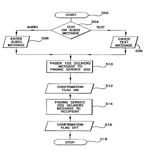
Referring to FIG. 5, the first party must select whether to enter a text or
audio message (step 504). If the first party selects a text message, then the first
party will subsequently enter the message with a keypad, a keyboard or other
device of the pager 102 (step 506). Alternatively, if the first party selects anaudio message, then the first party will subsequently enter the message with a
microphone 120, or keypad (step 508).
Upon entry of the message, the pager 102 delivers the message to the
paging service 202 by the wireless means previously described (step 510). In oneembodiment of the present invention, a confirm~tion flag will then be set in thepager 102 to indicate that the message has been delivered to the paging service
202 (step 512). The confirmation flag may be displayed on the pager 102.
Next, the paging service 202 will deliver the message to the pager of the
second party (step 514). The pager 102 of the second party may be part of the
paging system 100 of the pager 102 of the first party. In such case, the page will
be delivered in a manner described above (step 514). Alternatively, the pager 102
of the second party may be part of another paging system coupled to the paging
system 200 of the first party by wireline 204 or wireless 206 means.
Subsequent to the delivery of the message to the pager 102 of the second
party, the confi~m~tion flag is reset (step 516). Any corresponding display ofthe
2S confinn~tion flag on the pager 102 is termin~teA Then the method is complete
(step 518).
The present invention is described in terms of this example environment.
Description in these terms is provided for convenience only. It is not intended
that the invention be limited to application in this example environment. In fact,
after reading the following description, it will become apparent to a person skilled
in the relevant art how to implement the invention in alternative environments
CA 02258690 1998-12-17
W O 97/50261 PCTAUS97/11001
Conclusion
While various embodiments of the present invention have been described
above, it should be understood that they have been presented by way of example
only, and not limitation. Thus, the breadth and scope of the present invention
S should not be limited by any of the above-described exemplary embo(lim~nt~, but
should be defined only in accordance with the following claims and their
equivalents.