Note: Descriptions are shown in the official language in which they were submitted.
CA 02258759 1998-12-18
WO 97/50049 PCT/US97/11148
RESPIRATORY EFFORT DETECTION METHOD
AND APPARATUS
Field of the Invention
s The present invention relates generally to medical devices and
methods for use in the treatment of respiratory disorders. More particularly,
the
present invention pertains to methods of detecting respiratory effort for use
in the
treatment of respiratory disorders and devices regarding same.
Background of the Invention
1o Sleep apnea, an airway disorder, has been known for some time as a
medical syndrome in two generally recognized forms. The first is central sleep
apnea, which is associated with the failure of the body to automatically
generate the
neuromuscular stimulation necessary to initiate and control a respiratory
cycle at the
proper time. Work associated with employing electrical stimulation to treat
this
is condition is discussed in Glenn, ADiaphragm Pacing: Present Status~a ,
Pace, V.I,
pp 357-370 (July-September 1978).
The second sleep apnea syndrome is known as obstructive sleep
apnea. Ordinarily, the contraction of the dilator muscles of the upper airways
(nose
and pharynx) allows their patency at the time of inspiration. In obstructive
sleep
2o apnea, the obstruction of the airways results in a disequilibrium between
the forces
which tend to collapse airways (negative inspiratory transpharyngeal pressure
gradient) and those which contribute to their opening (muscle contraction).
The
mechanisms which underlie the triggering of obstructive apnea include a
reduction
in the size of the superior airways, an increase in their compliance, and a
reduction
25 in the activity of the muscle dilator. The muscle dilators are intimately
linked to the
respiratory muscles and these muscles respond in a similar manner to a
stimulation
or a depression of the respiratory center. The ventilatory fluctuations
observed
during sleep (alternately hyper and hypo ventilation of periodic respiration)
thus
favors an instability of the superior airways and the occurrence of
oropharyngeal
30 obstruction. In sleep apnea the respiratory activation of the genioglossus
muscle
CA 02258759 1998-12-18
WO 97/50049 PCT/US97/11148
2
has been particularly noted to be ineffective during sleep. The cardiovascular
consequences of apnea include disorders of cardiac rhythm (bradycardia,
auriculoventricular block, ventricular extrasystoles) and hemodynamic
(pulmonary
and systemic hypertension). This results in a stimulatory metabolic and
mechanical
effect on the autonomic nervous system. The syndrome is therefore associated
with
an increased morbidity (the consequence of diurnal hypersomnolence and
cardiovascular complications).
A method for treatment of sleep-apnea syndrome is to generate
electrical signals to stimulate those nerves which activate the patient=s
upper
1o airway muscles in order to maintain upper airway patency. For example, in
U.S.
Patent 4,830,008 to Meer, inspiratory effort is monitored and electrical
signals are
directed to upper airway muscles in response to the monitored inspiratory
effort.
Or, for example, in U.S. Patent 5,123,425 to Shannon, Jr. et al., a collar
contains a
sensor to monitor respiratory functioning to detect an apnea episode and an
electronics module which generates electrical bursts to electrodes located on
the
collar. The electrical bursts are transferred transcutaneously from the
electrodes to
the nerves innervating the upper airway muscles. Or, for example, in U.S.
Patent
5,174,287 issued to Kallok, sensors monitor the electrical activity associated
with
contractions of the diaphragm and also the pressure within the thorax and the
upper
2o airway. Whenever electrical activity of the diaphragm suggests that an
inspiration
cycle is in progress and the pressure sensors show an abnormal pressure
differential
across the airway, the presence of sleep apnea is assumed and electrical
stimulation
is applied to the musculature of the upper airway. Or, for example, in U.S.
Patent
5,178,156 issued to Wataru et al., respiration sensing includes sensors for
sensing
breathing through left and right nostrils and through the mouth which
identifies an
apnea event and thereby triggers electrical stimulation of genioglossus
muscle. Or,
for example, in U.S. Patent 5,190,053 issued to Meer, an intra-oral,
sublingual
electrode is used for the electrical stimulation of the genioglossus muscle to
maintain the patency of an upper airway. Or, for example, in U.S. Patent
5,211,173 issued to Kallok et al., sensors are used to determine the
effectiveness of
the stimulation of the upper airway and the amplitude and pulse width of the
CA 02258759 1998-12-18
WO 97/50049 PCT/US97/11148
3
stimulation are modified in response to the measurements from the sensors. Or,
for
example, in U.S. Patent 5,215,082 issued to Kallok et al., upon sensing of the
onset
of an apnea event, a stimulation generator provides a signal for stimulating
the
muscles of the upper airway at a varying intensity such that the intensity is
gradually increased during the course of the stimulation. Or, for example, in
U.S.
Patent 5,483,969 issued to Testerman et al., stimulation of an upper airway
muscle
is synchronized with the inspiratory phase of a patient=s respiratory cycle
using a
digitized respiratory effort waveform. A fully implantable stimulation system
is
described in Testerman et al. with a sensor implanted in a position which has
1o pressure continuity with the intrapleural space such as the suprasternal
notch, the
space between the trachea and esophagus or an intercostal placement.
However, even with these modes of respiratory disorder treatment,
there remain many practical difficulties for implementing them and other
therapy
treatments in medically useful systems. In particular, if stimulation for
respiratory
disorder treatment occurs in response to detected points of a respiratory
effort
waveform, it is important to be able to accurately and reliably detect such
critical
points. For example, if stimulation for treating sleep apnea is to begin
within a
predetermined period of time of inspiration onset and no later than, for
example,
200 ms after inspiration onset in order to avoid airway obstruction prior to
2o stimulation, accurate detection is required. Although various techniques
have been
used for detecting critical points for initiating stimulation, such as, for
example, in
Testerman et al., there is always a need in the art for other and/or improved
methods and devices for detection of such critical points and systems for
treatment
using such detection.
summary of the Invention
A method of predicting critical points in patient respiration in
accordance with the present invention is described. The method includes
monitoring at least one characteristic of a respiratory effort waveform of a
patient to
detect a respiratory event. A refractory period is defined that includes a
hard
3o refractory period during which time the respiratory event cannot be
responded to
and a soft refractory period following the hard refractory period. The
respiratory
CA 02258759 1998-12-18
WO 97/50049 PCT/US97/11148
event outside of the refractory period is detected as a function of a first
set of
predetermined parameters for the monitored at least one characteristic and the
respiratory event within the soft refractory period is detected as a function
of a
second set of predetermined parameters for the monitored at least one
characteristic.
In one embodiment of the method, the respiratory event is inspiration
onset. Further, the at least one characteristic of the respiratory effort
waveform
monitored is at least one of slope and amplitude.
In another embodiment of the method, the step of detecting
inspiration onset outside of the refractory period includes detecting
inspiration onset
as a function of monitored slope of the respiratory effort waveform. Further,
the
step of detecting inspiration onset within the soft refractory period includes
detecting inspiration onset as a function of monitored slope and amplitude of
the
respiratory effort waveform.
In another embodiment of the method, the refractory period is
~5 defined based on detection of inspiration offset. Further, the inspiration
offset is
detected as a function of the monitored slope and amplitude of the respiratory
effort
waveform. Yet further, the detection of inspiration offset includes validating
the
detected inspiration offset by comparing the amplitude of the sampled
respiratory
waveform to a validating offset threshold.
2o Moreover, in another embodiment, the refractory defining step
includes detecting inspiration offset, determining an average respiratory
period, and
providing an average time of inspiration. The refractory period, including the
soft
and hard refractory periods, are defined as a function of the detected
inspiration
offset, average respiratory period, and average time of inspiration.
25 A method for providing stimulation of a patient to treat respiratory
disorders in accordance with the present invention includes monitoring slope
and
amplitude of a respiratory effort waveform of a patient to detect inspiration
onset.
A refractory period is defined including a hard refractory period during which
time
an inspiration onset cannot initiate stimulation and a soft refractory period
following
3o the hard refractory period. An inspiration onset outside of the refractory
period is
detected as a function of the slope of the respiratory effort waveform and an
CA 02258759 1998-12-18
WO 97/50049 PCT/US97/11148
inspiration onset within the soft refractory period is detected as a function
of slope
and amplitude of the respiratory effort waveform. Stimulation is provided in
response to a detected inspiration onset.
In one embodiment of the method, the refractory period is defined
5 based on detection of inspiration offset. Further, inspiration offset is
detected as a
function of the monitored slope and amplitude of the respiratory effort
waveform.
In another method for providing stimulation of a patient to treat
respiratory disorders, the method includes monitoring slope and amplitude of a
respiratory effort waveform of a patient to detect inspiration onset and
inspiration
offset. A refractory period is defined that includes a hard refractory period
during
which time an inspiration onset cannot initiate stimulation and a soft
refractory
period following the hard refractory period. An inspiration onset is detected
outside
of the refractory period as a function of a first set of at least one of slope
and
amplitude criteria for the respiratory effort waveform and an inspiration
onset is
detected within the soft refractory period as a function of a second set of at
least one
of slope and amplitude criteria for the respiratory effort waveform.
Stimulation is
provided in response to detection of inspiration onset. The stimulation
terminates as
a function of detection of inspiration offset or a maximum stimulation time.
The
second set of criteria is set sufficiently sensitive relative to the first set
of criteria
2o such that stimulation, for one or more respiratory cycles, is applied as a
function of
the maximum stimulation time and the defined refractory period.
In another method of predicting critical points in patient respiration,
the method includes sampling the amplitude of the respiratory effort waveform
of a
patient. A sample signal is generated representative of at least one
characteristic of
the respiratory effort waveform based on each amplitude sample. The sample
signals representative of the at least one characteristic of the respiratory
effort
waveform are monitored and a respiratory event is detected as a function of at
least
two sample signals.
An apparatus for predicting critical points in patient respiration in
accordance with the present invention is also described. The apparatus
includes
monitoring means for monitoring at least one characteristic of a respiratory
effort
CA 02258759 1998-12-18
WO 97150049 PCTIUS97/11148
waveform of a patient and respiration detection means for detecting a
respiratory
event. The respiration detection means includes means for defining a
refractory
period including a hard refractory period and a soft refractory period
following the
hard refractory period, means for detecting the respiratory event outside of
the
_ refractory period as a function of a first set of predetermined parameters
for the
monitored at least one characteristic of the respiratory effort waveform, and
means
for detecting the respiratory event within the soft refractory period as a
function of
a second set of predetermined parameters for the monitored at least one
characteristic of the respiratory effort waveform.
to In various embodiments, the respiratory event may be inspiration
onset, the at least one characteristic of the respiratory effort waveform
monitored is
at least one of slope and amplitude of the respiratory effort waveform, and/or
the
respiration detection means may include means for detecting inspiration offset
as a
function of the at least one monitored slope and amplitude of the respiratory
effort
waveform.
A system for providing stimulation of a patient to treat respiratory
disorders in accordance with the present invention is also described. The
system
includes a sensor for providing a signal characteristic of a respiratory
effort
waveform of the patient, slope monitoring means for monitoring the slope of
the
2o respiratory effort waveform, amplitude monitoring means for monitoring the
amplitude of the respiratory effort waveform, and respiration detection means
for
detecting inspiration onset. The respiration detection means includes means
for
defining a refractory period including a hard refractory period during which
time an
inspiration onset cannot be responded to and a soft refractory period
following the
hard refractory period, means for detecting inspiration onset outside of the
refractory period as a function of the slope of the respiratory effort
waveform, and
means for detecting inspiration onset within the soft refractory period as a
function
of slope and amplitude of the respiratory effort waveform. The system further
includes means for generating a stimulation signal in response to a detected
3o inspiration onset and at least one electrode for delivering the stimulation
signal to
the patient.
CA 02258759 1998-12-18
WO 97/50049 PCT/US97/11148
7
Brief Description of the Drawings
Fig. 1 is a side sectional diagram of a patient having normal
respiratory activity.
Figs. 2a-c are graphs of normal respiratory waveforms (shown with
full normal inspiration at the peak). Fig, 2a shows a respiratory effort
waveform
and indicated phases of the respiratory effort waveform. Fig. 2b shows a graph
of a
respiratory airflow waveform with Fig. 2c showing the corresponding
respiratory
effort waveform.
Fig. 3 is a side sectional diagram of the patient of Fig. 1 at the onset
of obstructive apnea.
Figs. 4a and 4b are respiratory waveforms of inspiratory effort
showing normal inspiratory effort (Fig. 4a) and the change in normal
inspiratory
effort at the onset of an apnea event (Fig. 4b). Fig. 4c is a respiratory
waveform
showing respiratory airflow (as opposed to the respiratory effort waveform
shown
in Figs. 4a and 4b) in a patient during an apnea event.
Fig. 5 is a front sectional diagram of a patient showing the
implantable components of the stimulation system in accordance with the
present
invention.
Fig. 6 is a block diagram of the stimulation system shown in Fig. 5
2o further including physician and patient programming units.
Fig. 7 is a diagram of one embodiment of the physician programming
unit shown in block form in Fig. 6.
Fig. 8 is a diagram of one embodiment of the patient programming
unit shown in block form in Fig. 6.
Fig. 9 is a diagram showing one embodiment of the IPG/stimulator
shown in block form in Fig. 6.
Figs. l0a-l0e are illustrations showing various positions or
configurations for mounting the sensor shown in block form in Fig. 6 for
sensing
respiratory effort at a position in proximity to the posterior surface of the
3o manubrium.
CA 02258759 1998-12-18
WO 97/50049 PCT/US97/11148
_ 8
Figs. l la-l 1d are various views of one embodiment of the sensor
shown in block form in Fig. 6. Fig. l la is a side view of the sensor, Fig. l
1b is a
cutaway view showing the sensing element portion of the sensor with the sleeve
subassembly of the sensor cut partially away, Fig. l lc is a cross-section
view of the
s sensing element portion of the sensor, and Fig. l 1d is a cross-section view
of the
connector portion of the sensor.
Fig. 12a is a first embodiment of a block diagram of the signal
processing circuitry of the IPG/stimulator shown in block form in Fig. 6,
implemented in logic, for receiving the respiratory effort signal from the
sensor and
to providing an inspiration synchronized stimulation signal to the electrode
in
accordance with the present invention.
Fig. 12b is a second embodiment of a block diagram of the signal
processing circuitry of the IPG/stimulator shown in block form in Fig. 6,
implemented with a microprocessor, for receiving the respiratory effort signal
from
15 the sensor and providing an inspiration synchronized stimulation signal to
the
electrode in accordance with the present invention.
Fig. 13a is a top level flow diagram of the algorithm/control logic
shown in block form in Fig. 12a and 12b in accordance with the present
invention.
Fig. 13b is a flow diagram of the IPG-ON block of the flow diagram
20 of Fig. 13a.
Fig. 13c is a flow diagram of the Onset Detection block of the flow
diagram of Fig. 13a.
Fig. 13d is a flow diagram of the Offset Detection During
Stimulation block of the flow diagram of Fig. 13a.
25 Fig. 13e is a flow diagram of the Offset Detection block of the flow
diagram of Fig. 13a when stimulation is not occurring.
Fig. 13f is a flow diagram of the Suspension, Artifact, Therapy
Delay block of the flow diagram of Fig. 13a.
Fig. 13g is a flow diagram of the AGC Adjust block of the flow
3o diagram of Fig. 13a.
CA 02258759 1998-12-18
WO 97/50049 PCT/US97/11148
9
Fig. 14 is a graph showing a normal respiratory effort waveform
indicating various critical points detected in accordance with the present
invention,
various thresholds used in such detection, a normal differential pressure
signal, a
stimulus signal synchronously applied based on the critical points detected
with
s respect to the respiratory effort waveform, and an illustration showing the
definition
of a refractory period, all in accordance with the present invention.
Fig. 15 is a graph showing a respiratory effort waveform having an
artifact therein, a stimulus signal applied according to the present
invention, and an
illustration of the refractory period utilized to reject the artifact as an
inspiration
Zo onset, all in accordance with the present invention.
Fig. 16a shows a normal respiratory effort waveform and stimulus
applied according to the present invention. Fig. 16b shows a respiratory
effort
waveform of a patient with central sleep apnea and a stimulus applied
according to
the present invention utilizing a maximum stimulation time limit in accordance
with
i5 the present invention. Fig. 16c shows a central sleep apnea occurring
between
cycles of respiratory effort. Fig. 16d illustrates stimulation periods for
treatment of
the central sleep apnea occurring in Fig. 16c. Fig. 16e shows AGC gain for the
respiratory signal shown in Fig. 16c during the central sleep apnea.
Figs. 17a-c are graphs of one embodiment of a stimulation burst used
2o for stimulating the patient according to the present invention.
Fig. 18 is a block diagram of one embodiment of a microprocessor
based stimulation system.
Fig. 19 is a block diagram illustration of one diagnostic self test
strategy for a therapy system.
25 Figs. 20a-d are block diagrams of various internal diagnostic self
tests for the system shown in Fig. 18.
Detailed Description of thgEmbodiments
The following description relates generally to therapy systems
including implantable therapy and stimulation systems. Although many portions
of
3o this description are particularly applicable to the treatment of
respiratory disorders,
such as sleep apnea, by administering stimulation of musculature in synchrony
with
CA 02258759 1998-12-18
WO 97/50049 PCT/US97/11148
detected periodic events of the respiratory cycle, many portions of the system
are
equally applicable to other therapy systems. For example, automatic gain
control,
diagnostic testing, and methods for conserving energy are applicable to one or
more
other therapy systems such as, for example, drug delivery systems, blink
5 stimulation systems, and cardiac related systems.
With respect to the synchronization of stimulation to the respiratory
cycle of a patient to treat respiratory disorders, such synchronized
stimulation
requires a suitable respiratory sensor, proper placement of the respiratory
sensor,
and signal processing capability for converting the sensed respiratory effort
signal
to from the sensor to a stimulation signal for use in stimulating the patient.
In Fig. I
and Figs. 2a-c, normal respiratory activity is depicted. In Fig. 1, a patient
10 has an
airway 15 which remains patent during inspiration of air 20. Fig. 2a shows a
typical respiratory effort waveform for two complete respiratory cycles. This
analog waveform can be generated by various transducers such as, for example,
a
belt transducer worn snugly about the chest of the patient as used for
detection and
analysis of sleep apnea in sleep laboratories, an implanted pressure sensor
such as
that described in detail below, or any other transducer that provides a
respiratory
effort signal adequate for analysis to detect critical points thereof for use
in the
treatment of respiratory disorders, such as sleep apnea. Each wave of the
z0 waveform is characterized by a negative peak 30 on completion of
expiration, a
positive peak 35 on completion of inspiration (i.e. inspiration offset) and a
turning
point 40 which indicates the onset of inspiration (i.e. inspiration onset).
Each wave
of the waveform can therefore be separated into a period of respiratory pause
32, an
inspiratory phase 33 and an expiratory phase 34. Respiratory effort waveforms
having similar identifiable characteristics can be provided by monitoring
other
physiological signals such as intrathoracic pressure, intrathoracic impedance
or
electromyographic potentials. Other characteristics of the waveform could also
be
identified in connection with tracking and analyzing the respiratory waveform
to
monitor respiratory activity in sleep apnea treatment. In normal respiration,
the
3o respiratory effort waveform is related to airflow as set forth in Figs. 2b
and 2c. In
Fig. 2b a trace of normal respiratory airflow from a flow transducer is shown
while
CA 02258759 1998-12-18
WO 97/50049 PCT/LTS97/11148
11
Fig. 2c shows the corresponding trace of the normal respiratory effort which
produces the airflow.
In Figs. 3 and 4b, respiration in the same patient at the onset of an
obstructive sleep apnea event is depicted. Fig. 3 shows the patient 10 and
airway
15 with an airway obstruction 17 that is characteristic of an obstructive
apnea event.
Fig. 4a shows that in a normal respiratory effort waveform 43, the inspiratory
peaks 45a-d are of approximately the same amplitude. By comparison in Fig. 4b,
in
a waveform 47, the inspiratory peaks 48a-d become significantly greater in
amplitude at the onset of obstructive apnea than the immediately preceding
to inspiratory peak 49. This is reflective of the increased inspiratory effort
undertaken
by the patient in response to the difficulty of breathing through the
obstructed
airway.
In treatment of sleep apnea, the increased respiratory effort is
avoided by synchronized stimulation of a muscle which holds the airway open
during the inspiratory phase. Preferably, the muscle stimulated is an upper
airway
muscle, such as the genioglossus muscle stimulated by a cuff electrode placed
around the hypoglossal nerve. However, there may be other upper airway muscles
or nerves which can be used for stimulation to perform the same function and
also
other nerves or muscles apart from the upper airway which may be stimulated,
such
2o as the diaphragm, to treat respiratory disorders, such as, for example,
sleep apnea.
The effect of this stimulation on obstructive sleep apnea can be seen in the
airflow
trace of Fig. 4c. During a first period indicated as 46a, stimulation is
enabled
producing a normal respiratory airflow. During a second period indicated as
46b,
stimulation is disabled causing obstruction of the airway and reduction in
airflow
volume (apnea). During a third period indicated as 46c, stimulation is
resumed,
restoring patency to the airway and increasing airflow volume.
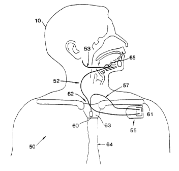
Components, and one implantable configuration, of an implantable
stimulation system 50 for providing inspiration synchronous stimulation
treatment
of sleep apnea are shown in Fig. 5. A block diagram of these components and
other associated programming components of the system SO for treating sleep
apnea
is shown in Fig. 6. As shown in Fig. 5, inspiration synchronous stimulation is
CA 02258759 1998-12-18
WO 97/50049 PCT/US97/11148
12
controlled by the implantable pulse generator (IPG)/stimulator 55. IPG 55,
also
shown in Fig. 9, provides inspiration synchronized stimulation, e.g. one or
more
stimulation pulses, through stimulation lead 52 to an electrode or electrode
system
65 placed around the hypoglossal nerve 53 for stimulation of the genioglossus
5, muscle of the upper airway. The electrode or electrode system 65 may be
positioned with respect to any other respiratory nerve, or other nerve or
muscle that
provides the desired stimulation result for the respiratory disorder treated.
The IPG
55, i.e. stimulator/controller, receives respiratory effort waveform
information via a
sensor lead 57 from a respiratory sensor or transducer 60 sensing the
respiratory
to effort of a patient 10.
One associated component of system 50 includes a physician
programmer 80, such as a laptop computer having programming software and
communication capabilities for communicating with the IPG 55, and which is
capable of programming the IPG 55 with various parameters in order to adapt
the
15 system for treatment of a particular patient. The system 50 of Fig. 5, is
therefore
adapted to be programmed using the physician programmer 80 as shown in Figure
7
by telemetry via transmitting/receiving element 81 electrically coupled to the
processor based programmer'80. Thereafter, the system 50 is used each night by
the
patient to prevent the closure of the upper airway during the inspiratory
phase of the
2o respiration cycle.
It will be apparent to those skilled in the art that such a system must
be made to be easy to use by the patient and since it is used without constant
medical supervision, it must be able to adapt to many different operating
conditions.
Therefore, the system 50 includes another associated component, i.e. patient
25 programmer 70, as shown in Fig. 8. The patient programmer 70 gives the
patient
the capability to turn the stimulator ON/OFF, adjust the stimulation amplitude
within preset limits programmed by the physician and adjust any other
stimulation
parameters or parameters of the IPG 55 as may be allowed by the physician,
such
as, for example, stimulation pulse rate, pulse width, dose time, therapy delay
time.
3o The patient programmer 70 provides both a visual and audio confirmation of
communication with the stimulator and further may include other patient
control
CA 02258759 2001-05-09
6742-686
13
elements for controlling parameters of the treatment of sleep
apnea. In addition, as described further below, the patient
turning the power on for initiation of the treatment using the
patient programmer 70 starts an automatic self stimulation test
and/or an automatic diagnostic self test of the components of
the system 50. Such a diagnostic self test may be performed at
any time, in addition to the initiation of the treatment period
by the patient. Further, such self stimulation test and
diagnostic tests are equally applicable to other therapy
systems in addition to the treatment of respiratory disorders,
such as sleep apnea.
The pressure sensor or respiratory transducer 60, may
be a dynamic relative pressure sensor such as that disclosed in
U.S. Patent 4,407,296 to Anderson or U.S. Patent 4,485,813
issued to Anderson et al. The pressure sensor 60 is surgically
implanted in a region that has pressure continuity with the
intrapleural space such as the suprasternal notch, the space
between the trachea and esophagus or attached to either of the
trachea or esophagus, an intercostal placement, or secured as
shown in Figs. l0a-l0e in a position for sensing pressure at
the posterior side of the manubrium as described in further
detail below. The suprasternal notch 62 and manubrium 63 of
sternum 64 as shown in Figure 5, are well known structures on
the upper chest that are in anatomical continuity with the
intrapleural space. It is also well known that chances in
intrapleural pressure provide a characteristic respiratory
effort waveform. The location for placement of the sensor is,
at least in part, chosen as a function of delay, i.e.
propagation time of a pressure waveform characteristic of
respiratory effort propagating from the respiratory ppint of
CA 02258759 2001-05-09
6742-686
13a
origin to the sensor position and as a function of the amount
of filtering necessary to achieve a usable sensed signal at a
particular location, i.e. filtering necessary to remove wave-
forms other than the waveform of the sensed characteristic,
such as cardiac waveform activity.
Preferably, the pressure sensor 60 utilized is a
pressure sensor assembly or sensor lead 115 similar to the
sensor lead sold under the trade designation of Medtronic Model
4321, available from Medtronic, Inc., Mpls., MN as modified and
represented in Figs. lla-lld. The pressure sensor assembly 115
CA 02258759 1998-12-18
WO 97/50049 PCT/lJS97/11148
14
includes a sensing section 120, a lead anchoring section 122, and a connector
section 124. A flexible lead body 121 forms a part of each section. The
sensing
section 120 includes, as shown in the detail views of Figs. l 1b and l lc, a
relative
pressure sensing element 126 which is mounted at an open distal end 123 of
assembly 115 opposite the connector section 124. The relative pressure sensing
element 126 senses respiration pressures through the use of piezo-electric
crystals
attached to a sensor diaphragm lying perpendicular to a longitudinal axis 125
extending through assembly 115. Pressures are transmitted to the diaphragm
through the portholes 128 on both sides of the sensing element 126. Pressure
to transmits from the portholes 128 to the diaphragm via a medical adhesive
132, such
as silicone rubber, which fills the nose cavity of the pressure sensing
element 126.
The sensor is driven, for example, with a fixed bias current on which the AC
pressure signal is coupled onto. Such a fixed sensor bias can range from about
8FA
to about 100FA. Such a sensor has a nominal output of about 3mV/mmHg over the
usable bandwidth of about 0.1 to about 100Hz.
The sensing element 126 has coil leads 136 electrically connected
thereto. The coil leads 136 are provided within bitumen tubing 138. The
bitumen
tubing 138 at the sensor section end and the sensing element 126 are
positioned in a
flexible tube 130 by medical adhesive 132 which also fills the cone of the
sensing
2o element 126 and covers the outer portions of the sensing element 126. There
is no
exposed metal surface of the sensing element 126 and the sensor is
electrically
isolated from the patient.
As shown in Fig. l td, a connector assembly 168, such as, for
example, a bipolar IS-1 compatible connector assembly, is electrically
connected to
the lead body 121, such as by crimping, to coil leads 136 in connector section
124
of the sensor assembly 115. Any connector assembly may be utilized that is
compatible with a connector port of the IPG 55. The connector includes sealing
rings 167 to ensure that body fluids do not disrupt the sensor assembly 115
and IPG
55 connection.
CA 02258759 1998-12-18
WO 97/50049 PCT/US97/11148
A sleeve attachment subassembly 140 has the sensing element 126
and a portion of the lead body 121 positioned therein. The sleeve subassembly
extends from a distal surface 174 of the sensing element 126 at the open
distal end
123 to beyond the interface between the lead body 121 and sensing element 126.
5 The sleeve attachment subassembly 140 includes an outer threaded sleeve 142,
an
inner threaded sleeve 144, and a soft umbrella ring 146. The sleeve attachment
subassembly 140 is mounted on the outer surface of the flexible tube 130 with
medical adhesive 132. The inner surface of the inner threaded sleeve 144 is
abraded to provide adhesion with the medical adhesive 132 to stably mount the
to sensing element 126 in the subassembly 140. The inner threaded sleeve 144
has
holes 148 about the longitudinal axis therethrough for molding a flexible
element,
i.e. soft umbrella ring 146, about the distal open end of the inner threaded
sleeve
144.
The soft umbrella ring 146 may be formed of silicone rubber and
is includes a flexible outer umbrella portion 152 that extends outward
relative to the
longitudinal axis and rearwardly relative to the distal open end of the inner
threaded
sleeve 144 and a fixed portion 154 of the umbrella ring 146. The flexible
outer
umbrella ring 152 performs the function of preventing tissue and bone growth
over
the distal open end 123 of the sensor assembly 115 when implanted. The soft
2o umbrella ring 146 is preferably formed of a radio opaque material so that
it can be
seen in imaging processes throughout implantation and explanation. Further,
the
umbrella ring 146 may include a treatment to prevent tissue and bone
overgrowth of
the sensor 126. Such treatment may include treatment with a steroid, such as
heparin, chemical coatings, surface roughening, or any other treatment that
reduces
such tissue and bone overgrowth.
The flexible element, i.e. umbrella ring 146, may be of any
configuration that prevents bone and tissue overgrowth. Further, if the sensor
is
implanted into a drill hole in the manubrium as described below, the flexible
element must be capable of being inserted and removed through the drilled
hole.
3o For example, the flexible element may be a donut shape or a simple flange
CA 02258759 1998-12-18
WO 97/50049 PCT/US97/11148
16
extending outward relative to the longitudinal axis 125 at the distal open end
of
inner threaded sleeve 144.
The outer threaded sleeve 142 includes a threaded portion 156 and an
unthreaded flange portion 158 extending substantially perpendicular to and
outward
relative to the longitudinal axis 125 of the sensor assembly 115. The outer
and
inner threaded sleeves 142 and 144 are utilized for adjusting the length of
the
subassembly 140 along the longitudinal axis 125. Further, they provide for
anchoring the sleeve subassembly, i.e. securing the sensor, in the manubrium
as
described further below with the unthreaded flange portion 158 of the outer
1o threaded sleeve 142 providing means for direct or indirect contact at the
anterior
side of the manubrium and with the flexible element 146 providing for direct
or
indirect contact at the posterior side of the manubrium. The adjustability is
important as the thickness of the manubrium varies from patient to patient.
One or
more holes I60 in the flange portion 158 are available for anchoring the
sensor
section 120 by suture to tissue or by bone screw to the anterior side of the
manubrium. The outer threaded sleeve 142 and the inner threaded sleeve 144 are
preferably formed of stainless steel, but can be any biocompatible material,
preferably a rigid biocompatible material.
In alternative configurations, the flange portion 158 may include a
2o soft cover thereabout or may be formed of a different shape as long as it
still
performs the function of direct or indirect contact with the manubrium to hold
the
sensing element 126 in position and/or includes means for attachment by a bone
screw, suture, or other securing means. For example, the flange portion 158
may
be a tab structure or multiple tabs extending away from and substantially
perpendicular to the longitudinal axis 125 from the end 159 of threaded
portion 156.
Further, the adjustability function of the inner and outer sleeves 142
and 144 may be provided by any structure that allows a length of the sleeve to
be
adjusted and then capable of being fixed at a particular length. For example,
two
telescoping members or sliding members may be used with, for example, a
ratchet
3o technique coupling the two and providing fixation at a particular length.
CA 02258759 2001-05-09
6E742-686
17
The anchoring section 122 includes lead body
anchoring sleeve 164 slidably mounted on the lead body 121 and
having suture grooves 165 for the anchoring of the lead body
121 when implanted. The lead body 121 is flexible such that it
can make a sharp right angle from the sleeve subassembly 140 at
the anterior region of the manubrium when the sensor assembly
115 is implanted to avoid skin erosion and bulge thereat. For
example, the lead body 121 may include pentifilar conductor
coils 136 in a bilumen silicon tubing. Alternatively, the lead
body 121 may include a right angle attachment at the anterior
region of the manubrium 63 for providing direction to the lead
body as it extends from the drilled hole at the anterior of the
manubrium 63.
One skilled in the art will recognize that various
connection techniques for connecting the sensing element 26 to
the IPG 55 may be utilized. For example, fiber optic
connection may be used, RF techniques may be used, and also
techniques using the body mass itself to propagate a signal
between components may be used. With use of at least some of
these connection techniques, a lead extending from the anterior
of the manubrium would not be present. Without the need for a
lead, the sleeve subassembly 140 for positioning and anchoring
the sensor in the drilled hole of the manubrium 63 could take
the form of any mounting element having an adjustable length.
The mounting element would no longer need to have an opening
therethrough, such as a sleeve, but could take the form of, for
example, a spring loaded elongated member with one open end for
holding the sensor. In other words, the mounting elements used
to mount the sensing element may take any elongated form with
an adjustable length and elements for securing it in the
manubrium hole by direct or indirect contact with the anterior
and posterior surfaces of the manubrium.
CA 02258759 2001-05-09
6742-686
18
The pressure sensor 60, such as pressure sensor
assembly 115, or any other suitable sensor for providing a
signal characteristic of respiratory effort, may be implanted
in various positions, such as those previously mentioned and
further including attachment to the esophagus or trachea or in
a position therebetween, or to any other soft tissue in the
suprasternal notch. Various positions for the sensor are
described in U.S. Patent No. 5,540,731 to Testerman. Further,
the sensor 60 may be positioned as shown in the Figs. l0a-10e.
Preferably, the pressure sensor assembly 115 is implanted
through a drilled hole in the manubrium 63 as shown in Figs. 10
and 10b. However, the sensor assembly 115 could be implanted
through the sternum 64 at any location thereof or through any
other bone such that the sensing element 126 is in communica-
tion with the intrathoracic region or a region with pressure
changes characteristic of respiratory effort.
As shown in Fig. 10b, the brachiocephalic vein 195,
also known as the inominant vein, is located in a region on the
posterior side of the manubrium 63 and erosion of the vein is
to be avoided. The present invention is configured to allow
sensing in the region where this vein is located. The pressure
sensor 60 is positioned in proximity to the vein, however, the
term in proximity to the vein means that the sensing element is
positioned in the region of the vein but is configured and/or
positioned such that erosion of the vein is avoided.
To implant the pressure sensor assembly 115, a small
pocket posterior to the manubrium 63 via the suprasternal notch
62 is created, such as by blunt dissection. A hole 185 is
drilled perpendicularly through the superior aspect of the
manubrium 63 and at the midline of the manubrium 63. It is
CA 02258759 2001-05-09
6742-.686
18a
desired that the sensor element 126, be placed near the top 187
of the manubrium 63 so that the pocket created on the posterior
side of the manubrium 63 is minimized lessening surgical
excavation risk and lessening the effects of cardiac signals
which are stronger at lower portions. Further, by implanting
the sensor assembly 115 toward the top of the manubrium 63, the
implanter can see the position of the umbrella ring 146 easily,
especially with mirrors. During drilling, a retractor is
placed on the posterior side of the manubrium 63 to protect
intrathoracic structures. Although placement of the sensing
element 126 near the top 187 of the manubrium is preferred, the
sensing element may be positioned anywhere along the length of
the sternum 64, although the manubrium is preferred. More
preferably, the sensing element is positioned about 0.5 cm to
about 3 cm from the top 187 of the manubrium.
CA 02258759 1998-12-18
WO 97/50049 PCT/US97/11148
19
When implanting the sensor, the length of the sensor section 120 of
the pressure sensor assembly 115 (i.e. length of subassembly 140) is maximized
by
turning the outer threaded sleeve 142 with respect to the inner threaded
sleeve 144
of the sleeve attachment subassembly 140. The sleeve attachment subassembly
140
of the sensing section 120 is then inserted in the drilled hole 185 and the
sensor
section length is adjusted such that the soft umbrella ring 146 is in direct
or indirect
contact with the posterior surface of the manubrium 63. When the sensor
section
120 is inserted into the drilled hole 185, the umbrella ring 146 collapses or
is
compressed against the side of the sleeve subassembly 140 and will spring
outward
to upon protruding into the posterior side of the manubrium 63. The umbrella
ring
portion 152 will act as an anchor and will prevent bone and tissue growth over
the
sensor opening. The implanter can utilize a finger to make sure the umbrella
ring
146 is flush with the posterior surface and to stabilize the sensor while the
outer
threaded sleeve 142 is turned to adjust the length of the sleeve attachment
subassembly 140 of the sensor section 120 to the thickness of the patient=s
manubrium 63. The distal tip 174 of the sensing element 126 should protrude in
the
range of about 1 mm to about 3mm posteriorly from the manubrium 63. A position
less than 1 mm results in a greater chance of tissue or bone overgrowth of the
sensing element 126. The distal tip 174 of the sensing element 126 is flush
with the
open end of the inner threaded sleeve 144. The sensor assembly 115 can then be
anchored on the anterior side of the manubrium by a suture or bone screw
through
the hole 160 of the unthreaded flange 158 of the outer threaded sleeve 142.
The
lead body 121 can be anchored with use of suture grooves 165 on the anchoring
sleeve 164.
With the IPG 55 implanted in a position on the upper chest, such as
just below the clavicle 61 as shown in Fig. 5, the lead body 121 of the
pressure
sensor assembly 115 is inserted in a tunnel created from the manubrium 63 to a
pocket created for implanting the IPG 55. When the IPG 55 is implanted, the
connector section 124 of the pressure sensor assembly 115 is connected to
sensor
3o port 58 of the IPG 55.
CA 02258759 1998-12-18
WO 97150049 PCT/US97/11148
Figs. lOc-l0e show alternative configurations for implanting the
pressure sensor 60 of the implantable stimulation system 50. As shown in Fig.
10c,
a pressure sensor 60 has a sensing element 197 positioned posterior to the
manubrium 63 with the lead body extending over the top 187 of the manubrium
63.
5 The lead is then brought down the anterior portion of the manubrium 63.
Various
anchors 178 are utilized to hold the sensing element 197 in place behind the
manubrium 63.
As shown in Fig. 10d, the sensor 60 is positioned in a manner
similar to that shown with respect to the drill through technique described
with
1o reference to Figs. 10a and IOb. However, in this configuration, the drill
hole 180
is made at an angle through the manubrium 63.
As shown in Fig. 10e, the sensor 60 is positioned substantially as
described in Fig. 10c. However, in order to protect against erosion of fragile
veins
posterior of the manubrium, the sensing element 197 and a portion of the lead
body
15 extending therefrom are covered with a soft guard 182. The guard 182 may
serve
the function of anchoring the sensor 60 as well as preventing any erosion of
the
brachiocephalic vein 195. The distal end 196 of the guard is open.
As demonstrated by the various configurations shown, many various
positions for implant of the sensor 60 are possible behind the manubrium yet
while
2o avoiding the fragile veins. The present invention contemplates the
positioning and
securing of various sensing elements with respect to the manubrium 63 to sense
pressure or any other characteristic for obtaining a respiratory effort
waveform at a
region posterior of the manubrium 63. The sensing elements are preferably
placed
in close proximity to the posterior surface of the manubrium 63.
The electrode or electrode system 65 of the implantable stimulation
system 50 may be any conventional electrode system for stimulation of muscles
to
treat respiratory disorders, such as sleep apnea. As previously described,
although
various respiratory muscles may be stimulated, stimulation of the genioglossus
muscle is utilized herein for treatment of sleep apnea. For example, the
electrode
3o system 65 utilized may be a Model 3990B Half Cuff Nerve Electrode available
from
Medtronic, Inc., Mpls., MN. This electrode and other suitable electrode
CA 02258759 2001-05-09
66742-686
21
configurations are described in U.S. Patent 5,344,438 to
Testerman et al., entitled ACuff Electrode@. This electrode is
utilized for placement around a respiratory motor nerve, such
as the hypoglossal nerve 53, with the stimulation lead 52 for
connection to the stimulation port 59 of IPG 55 as shown in
Figs. 5 and 9. One or more stimulation pulses are delivered to
the electrode 65 by the IPG 55 and transferred to the nerve
resulting in opening of the airway during respiration. It
should be readily apparent to one skilled in the art that any
suitable electrode for stimulating the desired muscle may be
utilized with the stimulation system 50 according to the
present invention. For example, the electrode may be a full
cuff electrode or any other electrode configuration for
capturing a respiratory motor nerve, such as the hypoglossal
nerve. Further, with respect to any other neuromuscular
stimulation systems which may benefit from the present
inventions described herein, the electrodes) may include any
electrodes) that provide the desired stimulation for such
systems.
The IPG 55 includes signal processing circuitry 200,
including detection algorithm or control logic 216, as shown in
block diagram form in Fig. 12a, respectively, and functionally
shown in the flow diagrams of Figs. 13a-13g. The signal
processing circuitry 200 processes the respiratory effort
signal provided by the pressure sensor 60, such as pressure
sensor assembly 115, and provides inspiration synchronized
stimulation via electrode or electrode system 65 for the
treatment of respiratory disorders.
To achieve adequate treatment of sleep apnea, the
stimulation is initiated by detection of inspiration onset, for
example, within a predetermined time of the actual physio-
CA 02258759 2001-05-09
66742-.686
22
logical onset, for example 200 ms. Sensing onset 200 ms early
(i.e. >predictive=) is desired. Stimulation is terminated as a
function of a detected inspiration offset. Slight errors of
approximately 300 ms or less in timing causing early offsets,
late offsets, or early onsets are typically permitted by the
treatment system. Late onsets, however, are preferably no
later than, for example, 200 ms. The requirement that
detection of onsets be no later than, for example, 200 ms, is
necessary to avoid airway obstruction prior to stimulation.
The timing to recruit a muscle to overcome obstructions which
occur prior to stimulation force such a requirement. The
present invention provides means for predictively detecting
onsets to meet this requirement. In addition to rigid timing
requirements, the detection algorithm operates reliably in the
presence of cardiac artifacts and motion artifacts.
The description herein is set forth in a manner such
that stimulation for treatment of sleep apnea occurs
substantially continuously and synchronous with inspiration
throughout the treatment period, except for time of non
stimulation such as suspension, dose, therapy delay, etc. as
determined by the algorithm described below. The treatment
period is the time period from when the treatment is turned on
to when the treatment is turned off. However, many of the
concepts described herein are equally applicable to sleep apnea
treatment systems wherein the onset of apnea is detected in
some manner and stimulation only performed after such detection
of apnea. For example, waveform analysis could be performed to
determine when an apnea is about to occur and then treatment by
stimulation could be initiated using concepts described herein.
Such detection of the onset of sleep apnea is described in U.S.
Patent 5,483,969 to Testerman et al.
CA 02258759 2001-05-09
66742-.686
22a
The detection algorithm or control logic 216 of the
signal processing circuitry 200, which will be described in
detail below, makes significant reference to Fig. 14.
Therefore, a brief description of Fig. 14 is appropriate at
this point to introduce the elements thereof and provide a
brief description of some of the functionality of the control
logic 216. Fig. 14 includes a normal respiratory effort
waveform 500 characteristic of the signal sensed by the
pressure sensor 60, a differential pressure signal 300, an
illustrative stimulus window 400 during which one or more
pulses are generated for treatment of airway disorders
synchronized with inspiration onset 501a and inspiration offset
502a, and a refractory period illustration wherein a refractory
period (R) is defined during at least a part of the expiratory
and pause periods 34 and 32 (Fig. 2a) of the respiratory cycle.
Further, Fig. 14 shows the respiratory period (T)
which is represented as the period from inspiration offset 502a
to inspiration offset 502b, the time of inspiration (TI) which
is shown as the time from inspiration onset 501b to
CA 02258759 1998-12-18
WO 97/50049 PCT/US97/11148
23
inspiration offset 502b, and a variety of thresholds which are utilized by the
detection algorithm/control logic 216 to control and provide inspiration
synchronous
stimulation. Such thresholds include analog onset threshold 520 and )V (i.e.
slope)
onset threshold 522 used for detection of inspiration onset, analog offset
threshold
524 and )V offset threshold 526 used for detection of inspiration offset (i.e.
latched
offset), Vref threshold 530 or zero crossing threshold used for validating or
declaring a detected latched inspiration offset, and AGC amplitude threshold
528
used in updating gain of the respiratory signal from the sensor 60.
)V is representative of the slope of the respiratory effort waveform
500. For illustration, the )V values can be generated by sampling the sensor
output
during a sample period, such as for example every 10 to 70 ms. The sampled
value
is then compared to the previously sampled value to obtain the net change in
voltage
(i.e. change in intrathoracic pressure) over the sample period. The net
change, )V,
is thus the pressure signal slope and therefore, representative of slope of
the
respiratory effort waveform.
The normal respiratory effort waveform 500 shows the amplitudes
and slopes which are characteristic of inspiration onset and offset. The
polarity of
the voltage respiratory effort waveform 500 in Figure 14 is inverted with
respect to
the polarity of the actual physiologic pressure measured by sensor 60.
Inspiration is
2o represented as a positive going voltage which indicates a negative
inspiration
pressure. Expiration is shown as a negative going voltage which indicates a
positive expiration pressure. The stimulation system 50 includes automatic
gain
control (AGC) that references or normalizes the respiratory effort signal. For
example, the signal may be normalized such that the positive signal peak is
1.2
volts, baseline (Vref) is 0 volts (DC}; and the negative signal peak is at
approximately -1.2 volts. In other words, a 2.4 peak to peak signal is
provided.
The AGC is described in further detail below and is applicable to any variable
input
signal characteristic of a periodic physiological parameter and is not limited
to only
the respiratory effort pressure signal described herein. The normalization of
such
3o signals is particularly advantageous when used in systems where timing
detection is
based on comparison to signal thresholds.
CA 02258759 1998-12-18
WO 97150049 PCT/US97/11148
24
Inspiration onset 501 is characterized as a rapid change in slope at an
amplitude above a predetermined level, i.e. analog onset threshold 520 (Figure
14),
and is detected by the control logic of the present invention as a function of
such
characterization. Inspiration offset 502 is characterized by a negative change
in
slope above a predetermined amplitude, i.e. analog offset threshold 524
(Figure 14).
A sustained non-positive slope and an amplitude above the predetermined
amplitude typically indicate an offset 502 and an offset is detected and
latched by
the control logic of the present invention as a function of such
characterization.
Physiological artifacts caused by cardiac pressures and body motions
add complexity to the respiratory effort waveform. Cardiac artifacts produce
slope
changes very similar to onset and offset slope changes. However, the slope is
not
typically sustained for the same duration. The respiratory amplitude level is
typically not altered by the cardiac artifacts. Therefore, the combination of
sustained slope and amplitude provides information to differentiate between
~5 inspiration events (onsets and offsets) and cardiac artifacts to avoid
stimulation at
the improper time. The control logic, for example, by using consecutive )V
samples to detect offsets and onsets, utilizes such characteristics to prevent
misdetection of valid onsets and offsets, i.e. offsets and onsets that are not
artifact
onsets and offsets.
2o Motion artifacts are similar to inspiration in both sustained slope and
amplitude. Figure 15 displays a motion artifact 542 on a respiratory waveform
540.
Depending on the source of the artifact (slow or fast body movement, etc.) the
slope and amplitude may be sufficient to satisfy the characteristics of either
an
inspiration onset and/or offset and stimulation based on such an artifact is
to be
25 avoided. As illustrated in Fig. 15, the control algorithm in accordance
with the
present invention utilizing a defined refractory period minimizes stimulation
from
occurring based on artifacts like artifact 542. Such distinguishing of the
artifact
from normal respiration will become apparent from the detail description of
the
control logic 216 below.
CA 02258759 1998-12-18
WO 97/50049 PCT/US97/11148
The techniques used by the algorithm or control logic 216 to
distinguish motion artifacts are based on known physiological parameters of
breathing during sleep. First, respiratory rate is known to be very stable and
consistent during sleep. For example, a typical breath-to-breath rate
variation of
s 1 S % has been established, with maximum variations as high as 3S % .
Periods of
wakefulness will have more breath-to-breath variations, coughs, sighs, etc.,
but
stimulation is not necessary nor desirable while the patient is awake. The
detection
algorithm establishes the presence of a stable respiratory rate or respiratory
period
in order for stimulation to occur when signal onset characteristics are
present, i.e.
1 o stimulation is suspended if a stable respiratory rate or respiratory
period is not
detected. Second, as the ratio between time of inspiration / total respiratory
period
(TI/T) is generally known, such as for example, between 0.30 and 0.40, a
refractory period (i.e. blanking period after inspiration has occurred), that
includes
both hard and soft refractory periods, is utilized to detect or predict onset
at a time
1S just prior to the next expected onset. These two ideologies, along with
others as
will become apparent from the further detail below, are utilized by the
algorithm to
reject motion artifacts.
The IPG SS, shown in Fig. 9, is any IPG or stimulator capable of
being configured for control of stimulation as required herein for treatment
of sleep
2o apnea. The IPG SS may be, for example, a Medtronic nerve stimulator sold
under
the trade designation ITREL II Model 7424 or a Medtronic nerve stimulator sold
under the trade designation ITREL III Model 7425, both available from
Medtronic
Inc., Mpls., MN., modified to include an input from the respiratory sensor 60
and
modified to include all the signal processing capabilities as shown in Fig.
12a for
25 control of stimulation as required herein. Each of these nerve stimulators
include
circuitry for providing a wide range of stimulation therapies which can be
used with
the present invention. The stimulator utilized should be capable of
implementing
the signal processing with minimum power consumption. Many various hardware
configurations may be utilized to implement the described signal processing
3o circuitry. For example, various designs incorporating hardware, software,
processors, analog circuits, digital circuits, combinations of the
aforementioned,
CA 02258759 1998-12-18
WO 97/50049 PCT/US97/11148
26
etc. may be used to perform the necessary signal processing and the present
invention is not limited to any particular configuration. Any IPG 55 utilized
requires an energy source.
The IPG 55 is implanted in the patient at a location such as shown in
Figure 5. However, any location normally utilized for implanting an IPG can be
used for the location of IPG 55 as would be readily apparent to one skilled in
the
art. A suitable implantable neurostimulator has advanced programmable features
permitting mode changes by transcutaneous RF telemetry. The patient-
controllable
parameters of the IPG=s operation, such as the amplitude of stimulation, can
therefore be controlled by the patient through a small hand-held telemetry
device,
i.e. patient programmer 70, shown in Figure 8. Likewise, the physician can
preset
additional operational parameters of the IPG 55 through a handheld telemetry
device
81 of the physician programmer 80, as shown in Fig. 7, held over the implanted
IPG 55.
As shown in Fig. 9, the IPG 55 includes two connector ports 58 and
59. The connector port 58 is for insertion of the sensor lead 57 and the
connector
port 59 is for insertion of the stimulator lead 52.
Fig. 12a is a first embodiment of a block diagram of the processing
circuitry 200 that includes sensor input circuitry 201 necessary to acquire a
2o respiratory signal from the pressure sensor 60 including means for biasing
the
sensor, filtering the sensor output and providing a normalized sensor signal.
Processing circuitry 200 further includes monitoring circuitry 203 for
monitoring
the sensed signal to synchronize stimulation with respiration.
In this first embodiment, as shown in Fig. I2a, a combination of
analog and digital circuits is used. Lbgic functions are provided without use
of a
microprocessor, i.e. purely analog and digital circuits. The analog front end
or
sensor input circuitry 201 for obtaining a respiratory effort signal includes
sensor
bias 202 required for biasing the pressure sensor 60. The pressure sensor 60,
for
example, the sensing element 126, requires a stable bias current in the range
of 8.8
:A to 100 :A. One method of sensor bias 202 includes providing a static bias
current in the range of, for example, 15 : A to 25 : A. Currents of this
magnitude
CA 02258759 1998-12-18
WO 97/50049 PCT/US97/11148
27
provide the best trade-off in terms of battery life and adequate immunity from
noise.
Alternatively, a second manner of sensor bias 202 includes providing a duty-
cycled
bias current. In this manner of operation, for example, a 80 :A to 100 :A bias
is
applied to the sensor just prior to the sampling the respiratory signal. Such
duty
s cycling provides lower power operation, i.e. saves battery life, and
provides noise
immunity benefits.
The pressure induced AC voltage from the sensor 60 is AC coupled
with a high pass filter pole at 0.1 Hz from the sensor bias current to a
filter 204, for
example, a 2 pole, 3 Hz RC low pass filter. The filter 204 is for anti-abasing
the
signal prior to providing the signal to the AGC amplifier 206 and to remove
the
higher frequency edges of non-respiratory artifacts, such as cardiac
artifacts, and
also motion artifacts.
The AGC amplifier 206 (Fig. 12a) may operate at a sampling
frequency using switched capacitor techniques or may be operated continuously.
15 The AGC amplifier 206 is responsible for normalizing the sensor output,
such as,
for example, to a consistent 2.4 volt peak-to-peak signal. The amplitude of
this
signal is then sampled and used by the analog threshold comparator 212 for
comparison to various thresholds and is presented to the ADC 214 for
conversion
into digital delta voltage measurements ()V's) via the )V nulling amplifier
208 for
2o providing an indication of the slope of the waveform. The outputs from the
analog
comparator 212 and ADC 214 are then utilized by algorithm/control logic 216 to
provide inspiratory synchronous stimulation as further described below.
The AGC amplifier 206 compensates for patient-to-patient and inter-
patient respiration amplitude variabilities. For example, pressure amplitudes
will
25 vary as a patient changes sleeping positions. The AGC amplifier 206
provides
adaptivity to the variable amplitudes and thus the physician is not required
to
program a gain setting. The AGC amplifier 206 also makes the detection
algorithm
much easier to implement as the thresholds, as described above and also
further
below, become relative to the normalized peak-to-peak signal and will operate
the
3o same even as the true pressure varies throughout the night.
CA 02258759 1998-12-18
WO 97!50049 PCT/US97/11148
28
In the first embodiment of processing circuitry 200, the measurement
of the pressure sensor signal amplitude is implemented in analog circuitry.
The
analog amplitude of the pressure signal is measured by comparison to various
thresholds and digital outputs are provided to the detection algorithm 216 as
a
function of such comparisons. Because of the fixed nature of the AGC amplitude
threshold 528, the signal amplitude is easily determined and readily
comparable to
the various analog thresholds in the analog domain. The one comparator 212 can
be multiplexed between the onset analog reference 520, offset analog reference
524,
Vref threshold 530, and AGC analog reference 528. As mention above, digital
to outputs are provided by the comparator 212 to the algorithm/control logic
216 to
indicate the crossing of such amplitude thresholds.
The sampled signal amplitudes of the signal from AGC amplifier 206
are used by the )V nulling amplifier 208 and ADC 214 to generate )V values of
a
desired bit size, for example, a 7 bit or 8 bit )V value. Configuring the
amplifier
~ s prior to the ADC 214 and nulling the present amplitude sample value with
the
previous sample amplitude value allows for digitally converting a change in
voltage
(i.e. slope) to )V=s. The nulling amplifier 208 has a gain, for example, of
16, to
restore amplitude to the differenced value. The ADC 214 sampling period is
synchronized {non-overlapping) to the stimulus to avoid degrading the ADC
2o sensitivity with stimulus circuitry noise. The stimulator frequencies of
the IPG 55
may be, for example, and thus the sampling frequencies may be, for example,
20,
30, 33, and 40 Hz. One skilled in the art will readily recognize that the ADC
214
and )V nulling and amplification block 208 could be switched, with the ADC 214
digitally converting the sampled amplitude to a digital value and the digital
values
2s from the present sample and previous sample used to determine a digital )V
value.
The )V values represent the change in amplitude over the sampling
period. Several consecutive )V values can be evaluated to confirm the
sustained
slope characteristic of inspiration onset or offset as described further below
with
reference to the detection algorithm. By using several, for example, two or
more,
3o consecutive )V samples, short duration (higher frequency) noise or cardiac
artifacts
can be rejected and thus misdetection of a valid onset or offset is avoided.
The
CA 02258759 1998-12-18
WO 97/50049 PCT/US97/11148
29
tradeoff for considering more than one sample is that delay is added by
waiting to
use multiple samples for detection of an onset or offset.
As an alternative to using digital )Vs for representation of slope of
the respiratory waveform to the detection algorithm 216, an analog
differentiator
5_ and peak detector could be utilized for slope measurement. However, the
availability of the )V's in the digital domain allows for precise threshold
settings
and variation in bandwidth by choosing the number of samples to evaluate.
A second embodiment of signal processing circuitry 400 for
performing the signal processing with substantially equivalent results to
signal
to processing circuitry 200 is shown in Fig. 12b. The sensor input circuitry,
including
the sensor bias 402, low pass filter 404, and AGC amplifier 406, is
substantially the
same as previously described with respect to the first embodiment. However,
the
monitoring circuitry 203, as indicated by the dashed line in Figure 12a, is
performed with the use of a microprocessor 410 and associated code. The
15 microprocessor 400 includes an internal analog to digital convertor (ADC)
414
which presents a converted sampled amplitude to the algorithm/control logic
416
and comparator 412, i.e. the logic and comparison are implemented in software.
In
this embodiment, )V=s are still determined based on the sampled signal from
the
AGC amplifier representative of slope of the respiratory effort waveform, and
2o sampled amplitude comparisons are still made with the various thresholds.
However, the sampled amplitude of the respiratory effort signal is immediately
converted to the digital domain by the ADC 414 and processed digitally by the
algorithm to obtain the )V=s. Further, the digitally converted sampled
amplitude is
digitally compared to digital thresholds 420, 424, 430, and 428 as necessary
to
25 carry out the functions as described further below. The algorithm 416 then
processes the )V, i.e. slope, information which it generated, and the
amplitude
comparison information generated by digital comparison 412, as described
further
below. Also as described further below, the processor 400 can be powered down
at
certain times when it is not required; conserving energy. Although both the
first
3o and second embodiment may be utilized in accordance with the present
invention,
along with various other configurations of digital or analog circuits, whether
with
CA 02258759 1998-12-18
WO 97/50049 PCT/US97/11148
the use of a processor or without, the remainder of the description shall be
made
with reference to Fig. 12a for simplification, except as otherwise noted and
for
specific features which are particularly beneficial to the processor based
configuration, such as processor power down.
5 The detection algorithm as shown in the flow diagrams of Figs. 13a-
13h shall now be described with reference thereto and with reference to other
figures herein as required. The detection algorithm or algorithm logic 216 as
shown in Fig. 12a resides in the IPG 55 of the implantable system 50 shown in
Fig.
5. The detection algorithm 216 detects inspiration onset and offset using
1o comparisons of sampled amplitude to multiple thresholds and )V values
representative of the slope of the respiratory effort signal. As described
previously
with reference to Fig. 12a, in the first embodiment, the digital outputs used
by
detection algorithm 216 to track the respiratory effort waveform, are the
onset and
offset amplitude threshold comparison outputs from the analog comparator 212
and
15 the digital )V slope value output from the ADC 214 (Fig. 12a). With respect
to the
second embodiment utilizing the microprocessor and associated code, the
digital
comparison of the digitally converted sampled amplitude to the various digital
thresholds along with the )V values generated using the digitally converted
sampled
amplitude, all generated inside the microprocessor, are utilized by the
processor
2o control logic algorithm 416. This respiratory effort signal information
concerning
amplitude and slope and the knowledge of respiratory timing parameters during
sleep are used by the algorithm to reject cardiac and motion artifacts and
control
stimulus of muscle in the treatment of sleep apnea.
A top level flow diagram of the detection algorithm/control logic 216
25 is shown in Fig. 13a. Generally, the detection algorithm is initiated at
IPG-ON
(block 600). The sensor signal is then sampled (block 610) at a programmed
sample rate and the appropriate outputs (i.e. )V=s and analog threshold
outputs) are
generated by the associated components of the system. Offset detection (block
620)
and onset detection (block 700) are then performed, with offset detection
taking
3o precedence over onset detection. If neither offset nor onset is detected
then the
sensor signal is further sampled and offset and onset detection repeated. If
offset is
CA 02258759 1998-12-18
WO 97/50049 PCT/US97/11148
31
detected, then various functions are performed such as determining whether
suspension mode is to be entered, therapy delayed, or AGC updated (blocks 640,
680). If onset is detected (block 700), then stimulation is initiated (block
720). The
stimulation is continued and the sensor sampled during stimulation (blocks
730)
until an offset is detected (block 740) and stimulation is terminated (block
760).
The various functions performed after an offset is detected (blocks 640, 680)
are
then performed.
The IPG ON command block 600 is a patient or physician controlled
function, where he/she turns the IPG "ON" via the patient programmer 70 or
1o physician programmer 80. The IPG 55 recognizes the IPG ON command (block
602) and begins a start-up sequence including dose control timer (block 603),
a
dose delay (block 604), a setting of initial conditions 606, and the entrance
of
suspension mode until a regular breathing pattern is recognized. The IPG ON
command may also initiate a patient self stimulation test and/or a diagnostic
self
test, as described further below.
Dose control timer (block 603) is immediately started by the on
command, l. e. , IPG-ON state. Dose is considered the treatment time over
which
the IPG 55 is on and stimulation synchronous with inspiration can occur as the
patient sleeps. A patient typically uses the system 50 during a regular
night=s
2o sleep. A patient may sleep anywhere from, for example, 1 to 15 hours. The
dose
period is initiated by the patient programmer 70 or a physician programmer 80
transmitting an IPG-ON command to the IPG. Dose is terminated or dose timer
timeout occurs by either reaching a maximum programmed dose time or the
patient
programmer 70 transmits an IPG-OFF command, i.e. IPG-OFF state. The dose
time-out provides an automated method for turning off stimulation in the
morning
after a night=s sleep. The maximum dose time is physician programmable and
may be for example, from 1 hour to 15 hours in 1 hour increments.
The initial IPG-ON command also initiates the dose delay period
{block 604). The delay waits a sufficient amount of time before starting
stimulation
3o to allow the patient time to fall asleep. Dose delay 604 is physician
programmable
from, for example, 0 to 75 minutes, in 5 minute increments. If stimulation
were to
CA 02258759 1998-12-18
WO 97/50049 PCT/US97/11148
32
start too soon, the patient may be disturbed and may have difficulty sleeping.
The
detection algorithm does not operate during dose delay 604 and minimal battery
power is consumed during this delay period, for example, in a microprocessor
based design, the microprocessor could be powered down.
At the end of the dose delay (block 604), the detection algorithm
parameters are initialized (or reset). The initial conditions include: Onset
Count =
0, Offset Count = 0, Artifact Count = 0, Average Respiratory Period Weighted
Sum (TWS) = 1 second, Max Stimulation On Timer = OFF. In addition, the start
AGC watchdog timeout timer as described further below is initialized to 1
second
and AGC gain is initialized to a mid-gain setting as described further below.
After
initialization of the conditions (block 606), as indicated above, stimulus is
indefinitely suspended, i.e. suspension mode is entered, until a regular
breathing
pattern is recognized (block 608).
Generally as will be explained further below, in suspension mode,
stimulation is disabled in the presence of artifacts or non-periodic
respiration.
Suspension is defined as a state where stimulation is suspended due to the
lack of a
stable respiratory pattern. If the present measured respiratory period (T) is
not
within a specified minimum and maximum time or if it is not relatively
equivalent,
i.e. within a certain tolerance (Tvar) of, a stored weighted sum respiratory
period
(TWS), then stimulus is suspended or suspension mode is entered. The detection
algorithm does not exit suspension mode until a measured respiratory period
(T) is
within the allowed variability from the weighted sum respiratory period (TWS).
As shown in Fig. 13a, during the sampling of the sensor 60 (block
610), the detection algorithm looks for a valid onset so that stimulation can
be
initiated (block 720). The onset of inspiration is characterized as a
sustained
increase in slope greater than a physician programmable )V onset threshold
value
and an amplitude greater than a physician programmable analog onset threshold
as
shown in Figure 14. An offset detection takes precedence over onset detection,
as
reflected by Offset Latched & Analog Vref block 622 (Fig. 13c).
CA 02258759 1998-12-18
WO 97/50049 PCT/US97/11148
33
As shown in block 700 of Fig. 13c, two consecutive )V's greater
than the physician programmed )V onset threshold value are required to
indicate a
sustained increase in slope. The comparison of sampled )V=s to the )V onset
threshold is shown as block 704. The time required to obtain the two samples,
for
example, may be between 40 ms and 80 ms, depending on the sampling rate; the
stimulus rate and sampling rate being the same. The stimulus rate is
programmed
or fixed by the physician and the )V onset threshold can be adjusted at the
same
time to compensate for shorter or longer sampling rates. For example, a faster
stimulus/sampling rate would result in smaller )V's since less change is seen
over
to the shorter sampling period. Thus, a lower )V onset threshold may be
appropriate.
As shown in block 704, if a )V does not exceed the )V onset
threshold, the onset counter for counting the number of times the )V onset
threshold
is exceeded is reset. If the )V onset threshold is exceeded, it is determined
whether
the stimulation has been suspended (block 706). Although a valid )V onset
threshold level was detected, if the IPG SS is in suspension mode, the onset
counter
is not incremented. Further sampling arid comparisons are then performed to
detect offsets. The offsets are detected to determine if a stable respiratory
signal is
present. If the IPG is not in suspension mode then it is checked to see
whether the
2o IPG is in refractory, i.e., a period of time between offset declaration and
onset as
described further below. Refractory (R), as shown in Fig. 14, includes both a
hard
refractory (HR) and a soft refractory (SR), i.e. a final portion of refractory
(R).
Refractory (R) is a processed time, based on a preprogrammed percentage of
measured patient respiratory periods (T), during which time the patient is
typically
denied access to stimulation, except possibly in soft refractory.
As shown in block 708, if the IPG is in refractory (R), then it is
checked to see whether it is in hard refractory (HR) or soft refractory (SR)
(block
710). If the IPG 55 is in hard refractory (HR), the onset counter is not
incremented
and more )V comparisons are made. If the respiratory effort signal is in soft
3o refractory (SR), then the amplitude of the signal is compared to the
programmed
analog amplitude onset threshold (block 714). If the signal does not exceed
the
CA 02258759 1998-12-18
WO 97/50049 PCT/US97/11148
34
analog onset threshold, the onset counter is not incremented but rather reset
to zero
and sampling is continued. If the signal exceeds the analog onset threshold,
then the
onset counter is incremented (block 716). Also as shown by blocks 708 and 712,
if
the )V onset threshold is exceeded and the IPG is not in the refractory
period, then
the onset counter is also incremented (block 712). If the onset counter is
equal to a
count of two, a valid onset is declared (block 716), the counter is reset to
zero, a
stimulation timer is initiated for controlling the maximum stimulation length
(block
718) as described further below, and stimulation is initiated (block 720).
The illustrative 200 ms onset previously described is obtainable,
particularly by adjusting the programmable )V and analog amplitude onset
thresholds along with refractory (R) and soft refractory (SR) discussed
further
below. By such adjustment, the algorithm can be made to be >trigger happy= or
predictive such that onset detection is not late and the refractory (R) is
maximized to
save battery life. For example, with use of the soft refractory period, the
analog
threshold may be set lower to allow a lower signal to exceed the threshold and
increment the onset counter. This still, however, blocks motion artifacts from
being detected as an onset is detected only if both slope and amplitude
thresholds
are exceeded during soft refractory, as opposed to just slope out of
refractory (R).
Generally, to declare an onset and thus start stimulation, in addition
2o to the )V onset threshold being exceeded by two consecutive samples, the
algorithm
must be out of refractory (R) during the two consecutive )V samples above
threshold or the pressure signal amplitude must be greater than the analog
amplitude
onset threshold and the algorithm must be in soft refractory (SR). Further,
the
algorithm must be out of dose delay, therapy delay, and suspension for
stimulation
to occur.
It should be apparent to one skilled in the art, that variations of onset
detection may provide suitable detection. For example, the number of counts
may
vary, the sampling rate may vary, more )V values may be used alone to detect
onset
in soft refractory as opposed to the use of both )V and amplitude information
in soft
3o refractory and other variation as would be readily apparent to one skilled
in the art.
CA 02258759 1998-12-18
WO 97/50049 PCT/US97/1114$
During stimulation, the sensor signal is still being sampled (block
730). Offset detection (block 740) is being performed using the sampled signal
during stimulation (block 740). If an offset is detected and latched while
stimulation is on, stimulation is terminated (block 760) when the latched
offset is
5_ validated or declared a valid offset. If offset is not detected,
stimulation proceeds
until a maximum stimulation period is reached as timed by max-stimulation on
timer
(block 718), at which time an offset is automatically declared.
Therefore, maximum stimulation time is used in the event that an
offset of the inspiratory phase is not detected. A maximum stimulation time
shall
1o terminate the stimulation and algorithm functions which typically occur at
a
regularly detected and validated offset are initiated. In other words, if
maximum
stimulation time is reached, an offset is declared and functions such as
calculating
weighted sum, starting refractory, etc. are initiated. When an offset is
detected and latched (block 740) and stimulation is terminated (block 760)
after the
15 latched offset is validated, the algorithm proceeds to suspension,
artifact, therapy
delay block b40 as will be described further below.
The detection and declaration of an offset during stimulation (block
740) and when stimulation is off (block 620) shall be described together, as
the flow
of both blocks is substantially similar with the exceptions as noted. Such
2o description shall be set forth with reference to Figs. 13d and 13e.
Inspiration offset is the most reliable and repeatable signal
characteristic to detect as the respiratory waveform slope changes from a
positive
slope to a sharp negative slope and the amplitude of the respiratory waveform
signal
reaches a peak value which is controlled by the AGC, for example, the 1.2
volts.
25 Therefore, detection algorithm operation and timing is centered around the
detection
of offsets, although other periodic events in the respiratory signal may also
be used.
Respiration timing, AGC control, and the accuracy, for example, of
the prediction of the next onset are all dependent on offset detection.
Generally, the
3o detection of offset requires three consecutive )V samples below the
physician
programmed )V offset threshold 526 (Figure 14) and the first of the three )V
CA 02258759 1998-12-18
WO 97/50049 PCT/US97/11148
36
samples is required to have an amplitude greater than the analog amplitude
offset
threshold 524 (Figure 14). Once these requirements are achieved, an offset is
detected and latched. The algorithm then waits for the respiratory effort
signal
level to fall below the Vref or zero crossing threshold 530 before validating
the
latched offset, i.e. declaring a valid offset and terminating stimulation.
Waiting for
the signal to fall below the Vref threshold 530 discriminates against cardiac
artifacts
riding on the signal, which may cause another offset to be prematurely
detected.
Alternatively, the offset could also be validated at any amplitude after the
offset
requirements are met, such as for example, onset threshold or even immediately
1o upon latching the offset.
With reference to the flow diagram of Fig. 13d, as the sensor signal
is sampled during stimulation (block 730), if an offset has not been declared
or
validated (block 742) and the maximum stimulation on time for stimulation has
not
been reached (block 744), a comparison of )V samples to the programmed )V
offset
~s threshold 526 is performed {block 746). If the programmed )V offset
threshold is
not met, then the algorithm resets the offset counter to zero and sample and
comparison continues. If the programmed )V offset threshold is met, then the
state
of the offset counter is queried (block 748). If the offset count is at zero
and the
analog respiratory effort signal is not greater than the analog offset
threshold to
2o produce a first offset count (block 750), then the offset counter is reset
to zero, the
offset counter is not incremented and sampling and comparison is continued to
detect an offset. If the offset count is equal to zero and the analog
respiratory signal
is greater than the analog offset threshold, then a first count is made (block
752). If
the offset count is not equal to zero (i.e., a first offset count has been
made), then
25 such consecutive )V samples that meet the )V offset threshold increment the
offset
counter (block 752). If the counter registers three consecutive counts during
three
consecutive sample periods (block 754) with the first offset crossing the
analog
offset threshold 524, an offset is detected and latched. Once the amplitude
falls
below Vref (block 742) the latched offset is validated and stimulus is
terminated. If
3o the three consecutive offset count requirement is not met, then the offset
counter is
reset, and sampling and comparison is continued for detecting offsets.
CA 02258759 1998-12-18
WO 97/50049 PCT/US97/11148
37
The offset declared or validated is then processed further by
Suspension, Artifact, Therapy Delay block 640 and an offset hysteresis timer
is
started (block 758). Offset hysteresis is utilized to prevent artifacts from
declaring
two offsets in a very short period of time. For example, if the offset slope
was too
shallow, multiple offsets could be triggered by artifacts in the signal
waveform
(e.g., if 6 consecutive )V=s satisfied the )V offset threshold and the analog
offset
threshold was met for at least the first of each set of three, then two
offsets could be
declared). Therefore, offset hysteresis provides a blanking period, for
example,
about 475 ms, after an offset has been declared during which no other offset
can be
1o declared. The blanking period is to provide a form of hysteresis such that
the
algorithm will only > see= one offset per respiratory cycle. The offset
hysteresis
should be sufficiently short to resume the detection of possible artifact
signals far
proper suspension mode and artifact counting operation.
Various alternatives to the offset detection portion of the algorithm
can be made. For example, the number of counts necessary for an offset to be
detected may be modified, the analog threshold may be required to be satisfied
for
all three )V samples as opposed to just one, the sampling rate may be
different,
different levels of analog thresholds may be used for declaration or
validation of an
offset to terminate stimulus and any other variation may be made that would be
2o apparent to one skilled in the art.
The offset detection when stimulation is off (block 620) is
substantially the same as described above with the exception that maximum
stimulation on time does not need to be checked (block 744) as stimulation is
off.
As mentioned previously, the detection algorithm/control logic 216
uses at least two ideologies including that the respiratory period (T) of
respiration is
known to be stable and consistent during sleep and that the ratio of the time
of
inspiration (TI) to the respiratory period (T) is typically known or can be
evaluated
with statistical measures. The detection algorithm 216 uses at least these two
ideologies and also respiratory timing statistics of sleeping humans to make
the
3o algorithm robust and exclusionary of misdetecting artifacts for onset and
offset. As
part of implementing the ideologies, the weighted sum respiratory period (TWS)
is
CA 02258759 1998-12-18
WO 97/50(149 PCT/US97/11148
38
used to build a running average of measured patient respiration periods (T)
and is
utilized in connection with various algorithm functions to control stimulation
and
reject artifacts. The various functions which employ the use of TWS include
refractory (R)/soft refractory (SR) function, suspension function, AGC
control, and
the artifact counter function. After a general discussion of the these
functions, the
suspension function, AGC control and artifact counter function will be
described
further with reference to the flow diagram of Fig. 13f and 13g. The use of
refractory (R)/soft refractory (SR) function has been previously described
with
reference to the flow diagram for onset detection (Fig. 13c).
The detection algorithm 216 evaluates the equivalence of every
patient respiration period (T) by comparison of measured periods (T) to the
continuously calculated weighted sum respiratory period (TWS) and to bounds
for a
respiratory period to evaluate whether respiration is stable. The detection
algorithm
having knowledge of the weighted sum respiratory period (TWS) and a
substantially
constant inspiration time (TI), also approximates the time between each offset
and
onset such that onsets can be predicted.
The geometric-series weighted sum used to generate the weighted
sum respiratory average (T) is weighted more heavily by the most current
measured
T periods. The algorithm adds the present weighted sum to the present T period
2o and then divides by 2. The result is expressed in the following equation: T
Weighted Sum (n) _ [T Weighted Sum (n-1) + T Interval (n)] / 2. The
maximum number of T periods contained in one sum is ten, but the T periods
beyond the fifth have an insignificant contribution to the sum. Not all
measured T
periods are utilized in determining TWS. The algorithm measures the patient
respiratory period (T) at each offset. If T falls out of the predetermined
bounds set
for T, i.e. Tmin and Tmax, for example, in the range of 1 second to 16
seconds,
indicating nonperiodic respiration, then the algorithm will consider the T
period
invalid. The invalid T periods are not added to the weighted sum (TWS).
With the weighted sum average respiratory period (TWS) calculated,
3o the refractory period (R) can be approximated as described below. Onsets
(and thus
stimulation) can be kept from occurring for a period of time in the refractory
period
CA 02258759 1998-12-18
WO 97/50049 PCT/US97/11148
39
(R) following the declaration of offset of inspiration. This time frame is in
the
expiration phase of respiration. Any physiologic or sensor disturbances
(artifacts,
noise, etc.) during this time period can be rejected as onsets. Stimulation is
thus
inhibited during at least a portion of refractory (R), but sampling continues
in order
s to detect the presence of artifacts and enter suspension mode, if necessary.
The refractory period (R) begins at the offset of inspiration (l. e. the
end of stimulus) and continues almost until when the next inspiration onset is
expected. A percentage of the weighted sum (TWS) is used to calculate the
refractory (R) duration. For example, with TINT ranges known from, for
example,
statistical analysis, the expiration portion of respiration and thus the
refractory
period (R) can be calculated as a fraction of the weighted sum (TWS). For
example, the calculated refractory period (R) may be implemented based on the
weighted sum by multiplying a physician programmable refractory multiplier of
0.375, 0.50, 62.5, or 0.75 times the weighted sum: refractory (R) =
(Refractory
1s Multiplier x Respiratory Period Weighted Sum (TWS)). Such particular
refractory
multipliers are for illustration only and any portion of T may be designated
as
refractory, such as from 0.1 to 0.75, particularly depending upon the
individual
patient=s respiratory cycle.
The weighted sum respiratory period (TWS) is initialized upon the on
2o command for the IPG 55 to be 1 second. The algorithm remains in suspension
mode as described further below until the TWS is equivalent to the present
measured T, i.e. periodic respiration is determined. The algorithm does not
use
refractory (R) to blank onsets until suspension mode is exited. This insures
that the
weighted sum (TWS) will have established a valid value and thus the refractory
(R)
25 will also be a valid duration for predicting onsets and blanking artifacts.
Refractory (R) is limited to a minimum time. This is achieved by
only updating the weighted sum (TWS) for T periods greater than 1 second and
therefore the weighted sum (TWS) has a minimum of 1 second. As such the
refractory (R) minimum time is given by: Minimum Refractory = (Refractory
3o Multiplier x 1 second). The establishment of a minimum refractory time is a
safety
guard against over stimulation by establishing some minimum of blanking time.
CA 02258759 1998-12-18
WO 97/50049 PCT/US97/11148
Soft refractory (SR) is implemented in the final portion of the
refractory period (R). The other portion of refractory (R) is referred to as
hard
refractory (HR) and is shown in Fig. 14. In hard refractory (HR), stimulation
is
not allowed, i.e. onsets are not responded to. In the soft refractory (SR)
period of
s refractory (R), as shown in Fig. 14, an onset (i.e. stimulation) is allowed
if the
analog onset threshold and the )V comparison as described with reference to
Fig.
13c both indicate an onset. The soft refractory {SR) portion of refractory
period
(R) may be a fraction of, for example, 12.5 % of the weighted sum (TWS).
Therefore, for illustration, if refractory (R) is 75 % of the weighted sum,
then the
to soft refractory (SR) is during the 62.5 % to 75 % portion of refractory
(R).
Alternatively, the soft refractory (SR) could be a function or
percentage of refractory (R). Further, the refractory functions may be based
on
stimulus duration as opposed to respiratory rate. With this alternative, the
algorithm would measure the duration of the previous stimulus interval and
multiply
15 the interval by a predetermined value. A further alternative for refractory
could be
based on both stimulus duration and the respiratory period (T) or any other
alternative respiratory timing parameter that would be suitable for defining a
refractory, hard refractory, and/or soft refractory period following offset
detection,
such as TI.
2o Suspension mode, which also utilizes TWS, provides several
benefits. For example, the suspension function keeps the patient from being
overly
stimulated, i.e. patient comfort. Further, this technique also conserves
energy to
increase battery life. In suspension mode, stimulation is disabled in the
presence of
artifacts or non-periodic respiration. Suspension is defined as a state where
25 stimulation is suspended due to the lack of a stable respiratory pattern.
If the
present measured patient respiratory period (T) is not within a specified
minimum
and maximum time or if it is not relatively equivalent to, i.e. within an
allowed
variability of, a stored weighted sum respiratory period (TWS), then stimulus
is
suspended, i.e. suspension mode is entered. The detection algorithm does not
exit
3o suspension mode until a measured patient respiratory period (T) is within
the
allowed variability from the weighted sum respiratory period (TWS) . The
CA 02258759 1998-12-18
WO 97/50049 PCT/US97/11148
al
programmable values of allowed T variability (hereafter referred to as Tvar)
may be
for example, 25 % , 33 % , 50 % , and infinite. Each and every offset is
considered
as a measure of the respiratory period (T) and/or the presence of artifacts.
While in
suspension mode, the algorithm continues all other signal processing tasks
such as
threshold comparisons, AGC adjustments, and weighted sum calculations.
Generally, suspension is entered by the algorithm under the following
conditions indicative of nonperiodic respiration. First, upon initialization
of the IPG
55, the algorithm is in the suspension state, as shown in Fig. 13b, block 608,
after
the IPG 55 is turned ON and dose delay (block 604) is completed. Second, if
the
to presently measured respiratory period (T) is less than the minimum or
greater than
the maximum bounds programmed for T, suspension mode is entered, i.e. the
bounds of 1 second and 16 seconds as previously mentioned. Third, if the
present
respiratory period (T) is not within a programmed allowed variability, i.e.
Tvar,
suspension mode is entered. And last, suspension is entered after the
completion of
a therapy delay initiated with use of the artifact counter as described below.
It
should be readily apparent to one skilled in the art that the number of
respiratory
violations of, for example, Tmin, Tmax or Tvar, which are required for
suspension
mode to be entered may vary. For example, more than one violation may be
required to enter suspension.
2o The above described suspension mode technique disables stimulus in
the presence of physiologic artifacts such as arm movements and head movements
Such movements occur only when the patient is in shallow sleep or awake. An
example of the benefit of suspension mode is the case of a sleeping patient
awakening to a phone call. Suspension mode will be entered as the patient
moves
about and stimulation will be inhibited while the patient speaks on the phone.
Suspension mode is also intended to disable stimulus in the presence of non-
physiologic and environmental noise sources. During suspension mode, the
algorithm continues to evaluate the signal and will exit suspension mode and
return
to stimulus as soon as a periodic respiratory signal is re-established.
Therefore,
only the prevention of stimulus conserves energy as the sensor must still be
operated.
CA 02258759 1998-12-18
WO 97/50049 PCT/US97/11148
42
As mentioned above, an artifact counter is used to initiate a therapy
delay during which time stimulation is disabled. This is technique also
conserves
energy, lengthens battery life, and rejects artifacts. If the respiratory
waveform
continues to be too variable or multiple motion artifacts are occurring while
in
suspension mode, then the artifact counter will cause the algorithm to enter
therapy
delay. While in suspension mode, the number of offsets are counted by the
artifact
counter, in which case an offset is defined as the falling peak of either a
respiratory
or artifact event. If a maximum number of offsets are counted during
suspension
mode, then the algorithm enters a therapy delay period. The maximum artifact
1o count is physician programmable, for example, to 10, 20, 40, or 80. During
therapy delay, initiated by the artifact counter, the algorithm does not
process the
respiratory waveform signal and therefore, energy is conserved by turning the
pressure sensor off and by preventing stimulation. Upon completion of the
therapy
delay period, the algorithm resets to an initial state (AGC gain and weighted
sum
reset, etc.) like when the IPG 55 was first turned on. Sampling the signal in
the
suspension mode is then resumed.
The counting of offsets during suspension mode is a simple method
for determining the extent of non-respiratory activity. If frequent offsets
are
occurring, then this indicates that extensive movement exists and the
algorithm shall
2o transition quickly into therapy delay. If suspension mode occurs due to a
short
duration event, the offset artifact count will not reach the maximum, and
stimulus
will resume after the steady respiration rate has been re-established. If
suspension
mode is maintained by a variable respiratory rate, the offset artifact count
will
eventually lead to a maximum artifact count and therapy delay from counting of
offsets. It should be noted that the artifact count is reset to zero upon
exiting
suspension mode.
The artifact counter function also provides the patient a method to
quickly terminate stimulation without the use of the patient programmer 70.
This is
accomplished by tapping in the proximity of the pressure sensor to induce
artifact
3o counts. Such tapping allows the patient to terminate stimulus for the
duration of
therapy delay in the event that the patient programmer 70 is lost or fails
during the
CA 02258759 1998-12-18
WO 97/50049 PCT/US97/11148
43
night. Such termination could also be accomplished by use of a magnet being
passed over a reedswitch built into the IPG 55.
Offset hysteresis, as previously described, is also used to conserve
energy, as during this period of time the sensor can be shut down. Further,
although some functions described herein may depend on the sensor functioning
during refractory, with some modifications to the algorithm, the sensor may
also be
shut down during refractory, particularly hard refractory, as stimulation is
prohibited. Thus, energy can also be conserved by shutting down the sensor
whenever the respiratory waveform is not needed by the remainder of the
system.
to With reference to Fig. 13f, the flow of the suspension and artifact
counting techniques in the detection algorithm shall be described. If offset
is
detected while stimulation is off (block 620), then it is determined whether
the
algorithm is in suspension as described above. If the unit is in suspension
mode,
artifacts (i.e. offsets, both inspiratory and artifact) are counted to
determine if the
algorithm should go into therapy delay (block 644). If the count exceeds some
predetermined number, such as, for example, 16 counts, then the artifact
counter is
reset to zero, suspension mode is exited and activation of programmed therapy
delay is entered (block 666). The therapy delay time is also started upon
receiving
the IPG on command during either an already occurring therapy delay (block
666)
or dose delay (block 604) (Fig. 13b). After the therapy delay is exited, the
initial
conditions are set, substantially the same as when the IPG is turned on with
the
patient programmer (Fig. 13b).
If an offset has been detected either during stimulation or when
stimulation is off, respiratory period (T) is measured (i.e. offset-to-offset
or the
time from the last offset to the current offset) (block 648). The current
measured
respiratory period (T) is then compared to Tmin and Tmax (block 650). If the
current respiratory period (T) is not greater than Tmin and less than Tmax,
then
refractory (R) is started (block 652) based on a percentage of the previous
weighted
sum respiratory period (TWS). Further, if three consecutive current
respiratory
3o periods (T) measured do not meet these requirements, then the algorithm
goes into
CA 02258759 1998-12-18
WO 97/50049 PCT/US97/11148
44
suspension mode and stimulation is not allowed, otherwise, artifact counter is
reset
to zero and suspension mode is exited.
If the current respiratory period (T) is greater than Tmin and less
than Tmax, then the current measured respiratory period {T) is added to the
weighted sum average respiratory period and a weighted sum (TWS) of the
previous
breaths is calculated to determine a new average weighted sum respiratory
period
(block 654). Refractory is started (block 652) based on a percentage of the
new
average weighted sum, as updated. Further, the current respiratory period (T)
measured is compared to the weighted sum from the previous offsets (i.e. the
old
weighted sum prior to the addition of the current T) (block 656). If the
current T is
equivalent, i.e. meets Tvar, indicating periodic respiration, then the
artifact counter
is reset to zero and suspension mode is exited. Otherwise, it is once again
determined if three current respiratory periods (T) measured do not meet the
Tmin,
Tmax and Tvar requirements (block 658). As before, if three consecutive T=s do
not meet the Tmin, Tmax, and Tvar requirements, then the algorithm goes into
the
suspension mode or suspension mode is continued (block 670) and stimulation is
not
allowed, otherwise, artifact counter is reset to zero and suspension mode is
exited
(block 662).
The number of consecutive out of tolerance T = s necessary to enter
2o suspension mode is programmable. For example, the number can be set at one
or
other suitable values. Further, Tvar can be set to infinity which overrides
the
suspension feature and suspension is never entered.
In either case, whether suspension mode is entered or exited, the
automatic gain control (AGC) is continually utilized or adjusted (block 680)
as shall
be described with reference to Fig. 13g. However AGC is not operational during
treatment delays, i.e. dose delay or therapy delay, as the pressure sensor
need not
be operated during this delay time, conserving battery life. The AGC control
described herein is applicable to the provision of any signal characteristic
of a
periodic physiological parameter for use in a therapy system. For example, the
3o normalization provided by the AGC control is particularly applicable to
systems
which perform functions based on comparing the signal to the thresholds.
CA 02258759 1998-12-18
WO 97/50049 PCT/US97/11148
The AGC amplifier 206 (Fig. 12a), as described previously, is
required to normalize the pressure sensor output to a consistent peak to peak
signal,
for example, 2.4 volt peak-to-peak signal. The operation of the AGC for the
system 50 is dependent on the detection algorithm for synchronizing gain
increment
s and decrements. The AGC consists of a plurality of gain steps, for example,
64
gains steps. Gain is incremented exponentially such that each gain step
increases by
the same percentage, for example, about 5.3 % . However, gain may be performed
by other than exponential techniques, such as, for example, techniques that
produce
equivalent increases as opposed to equivalent percentage increases.
10 Generally, the AGC functions in the following manner. The gain is
incremented or decremented once per respiratory period (T). The AGC gain is
changed immediately following detection of a periodic event in the waveform,
i.e. a
>true= offset. True offset is defined here so as to indicate those offsets
which are
likely to be from an actual, stable inspiration offset and not a motion
artifact or
~s irregular breathing. The algorithm determines an offset is true if it does
not occur
during refractory (R) (including both soft refractory and hard refractory), as
during
refractory (R) it is assumed that the offset is an artifact offset. Offsets
resulting in a
respiratory period (T) outside of the predetermined bounds set for the
periods, such
as, for example, less than 1 second or greater than 16 seconds, are also
considered
2o invalid.
It is desirable to not change gain during refractory as the offsets
which occur in this period may be of large amplitude, due to a motion
artifact, and
gain may be unnecessarily updated. Also, the refractory sets a limit on how
fast the
gain can be changed. Thus, if a rapid burst of artifacts occurs during
refractory (R)
25 then there will be no rapid change in gain. If a burst of artifacts occurs
while the
algorithm is not in refractory (R), then the first artifact will be considered
an offset
and subsequent artifacts will not change the gain as they will be in
refractory (R).
Thus, rapid offsets can only change the gain once during a respiratory cycle,
i.e.
increment or decrement once. AGC control is performed during suspension mode,
3o along with offset detection and refractory, as only stimulus is inhibited
and an
CA 02258759 1998-12-18
WO 97/50049 PCT/US97/11148
46
exceeding of the artifact counter results in a therapy delay while in
suspension
mode.
An AGC watchdog timer also forms a part of AGC control. The
AGC watchdog timer is reset each time a valid offset occurs resulting in the
AGC
gain being updated. The watchdog timer will otherwise time-out at, for
example,
1.5 times the respiratory period weighted sum (TWS) or in other words, the
watchdog timer time-outs at 50 % beyond the point where an offset is expected.
At
time-out an AGC threshold is used to determine if the AGC gain should be
incremented or decremented by one step. The watchdog timer will continue to
to time-out and increment or decrement until offsets begin occurring. The
offsets then
take control of the AGC operation. Therefore, the watchdog timer gets the gain
to
a level such that offsets can be detected and normal AGC control via offsets
can be
established, particularly when the IPG 55 is first turned on.
The AGC is initialized to a mid-range setting. If this initial gain is
too low, the watchdog timer may have to cycle several times before offsets
begin to
occur and equilibrium is reached. The watchdog timer is loaded with a
predetermined time, for example, 1 second at the initialization of the
algorithm.
Thus, the gain will increment one step per second until offsets are achieved,
unless
the initialized gain is too high, in which case each offset and/or the
watchdog timer
2o will decrement the gain until equilibrium is reached. The AGC is reset or
reinitialized at each exit of therapy delay or dose delay.
Generally, therefore, gain is updated when an offset is detected
following onset, even while in suspension mode or gain is updated when a
watchdog
time out occurs if an offset is not detected within a predetermined period of
time.
2s However, offsets detected while in refractory (R), whether or not in
suspension
mode, do not initiate gain update. Further, since offsets are not even looked
for in
dose delay or therapy delay, AGC is not updated during this time period.
Typically, after initialization, the gain is incremented with use of the
watchdog
timer until valid offsets can be detected. Thereafter, the AGC typically
controls the
3o gain by toggling between increments and decrements to keep the gain at a
particular
level, i.e. the AGC threshold 528 (Fig. 14) and the waveform is normalized.
CA 02258759 1998-12-18
WO 97/50049 PCT/US97/11148
47
The flow of AGC control 680 is shown in Fig. 13g. AGC is run
virtually simultaneously with the determination after an offset is detected of
whether
the algorithm should be in suspension or not as described previously with
reference
to Fig. 13f. As such, block 650 (Figs. 13f and 13g) appears in both flow
diagrams.
5_ AGC is not performed until the current measured respiratory period (T)
meets the
requirements of being greater than Tmin and less than Tmax (block 650), i.e. a
somewhat stable periodic signal is sensed. Further, AGC update is performed if
Tvar is set to infinity (block 650), regardless of the Tmin and Tmax
requirements,
i.e. if Tvar is set to infinity then all requirements for T are disabled for
suspension
and AGC functions. If the gain is not updated the sensor is continued to be
sampled
(block 610) and offset and onset detection is performed (blocks 620 and 700).
If
such requirements are met, then it is determined whether the algorithm is in
refractory (R). If the algorithm is in refractory (R), then the gain is not
updated
(block 684). If the algorithm is not in refractory, then gain is either
incremented or
15 decremented based on a comparison with a predetermined AGC amplitude
threshold
(Fig. 14) (blocks 686 and 690). If the amplitude of the respiratory effort
signal is
less than the AGC threshold at any time since the previous update, then gain
is
incremented at, for example, 'offset, watchdog timeout or any other periodic
event
in the respiratory cycle. If the amplitude of the signal is greater than the
threshold
2o at any time since the previous update, then the gain is decremented at
offset,
watchdog timeout or any other defined periodic event in the cycle. The watch
dog
timer is reset at each and every AGC increment or decrement. However, at any
time when no offsets are detected in a specified period of time, then the gain
is
incremented or decremented using the watchdog timer, i.e. a time based on the
2s weighted sum respiratory period (block 692). Generally,
therefore, for a signal characteristic of a periodic physiological parameter,
such as
respiration, which include multiple periodic cycles, gain is updated when a
periodic
event is detected. The gain, however, is updated only once during a periodic
cycle.
Further, a watchdog timeout occurs if the periodic event is not detected and
gain is
3o updated even though a periodic event is not detected. Thus, the gain will
be
CA 02258759 1998-12-18
WO 97!50049 PCT/US97/11148
48
adjusted once per periodic cycle upon detection of a periodic event or at a
watchdog
timeout.
Other alternative methods of AGC implementation may be utilized
with the present invention. For example, the AGC may adjust the amplifier gain
s after each amplitude sample has been taken. The magnitude of the sample
would
then be processed digitally to adjust the gain such that the amplifiers
operate in mid-
dynamic range. This technique has the advantage of quick gain adjustments and
continuous digital knowledge of the signal amplitude. However, the AGC would
not provide normalization and thus relative threshold measurements are not
possible.
In general, the algorithm must be in the following state for
stimulation to occur. A valid onset consisting of a certain number of )V=s,
for
example, two )V=s, above )V onset threshold must be detected. The refractory
period (R) must be complete or the analog onset threshold must be crossed if
the
algorithm is in soft refractory (SR). The algorithm must not be in suspension
mode
and the algorithm must not be in either dose delay or therapy delay.
Further, any one of the following events will terminate stimulation: a
predetermined consecutive number of )V=s, for example, three consecutive )V=s,
below )V offset threshold with the first )V sample below the )V offset
threshold
2o satisfying the analog offset threshold (the offset must also be validated
by
comparison to another threshold level such as zero crossing); maximum
stimulation
time is reached; a patient initiates therapy delay by giving another IPG on
command
when treatment is on; end of the dose timer period after a night=s sleep; and
an
IPG-OFF command.
25 Moreover, in general, implantable stimulation system 50, operates in
the following manner. At some point following the IPG 55 implant, the patient
will
undergo a sleep laboratory evaluation where algorithm parameters, such as
those
programmable parameters described herein (onset and offset thresholds,
refractory,
dose times, etc. ) are optimized to achieve proper stimulation for the
individual
3o patient. The stimulation parameters (amplitude, rate, and pulse width) are
also
adjusted to achieve the muscle stimulation necessary to overcome respiratory
CA 02258759 1998-12-18
WO 97/50049 PCT/US97/11148
49
obstructions. After being programmed by the physician, the patient is provided
with a hand-held patient programmer 70 which is primarily used to turn the IPG
ON
and OFF each evening and morning, respectively. The patient programmer 70 also
may provide the patient with display indications regarding system information
such
as battery life warnings, failed stimulus components, etc., and further may be
used
to automatically initiate other diagnostic and stimulation testing as
described further
below. The implanted stimulation system 50, upon initialization of treatment,
then
utilizes the sensed respiration effort waveform to detect critical points in
the
waveform to provide inspiration synchronous stimulation for treating
respiratory
disorder in accordance with the algorithm as described above.
The system 50 can also be used for patients with central apnea, or
patients whose central nervous system provides no drive to breath. Central
apneas
often occur in obstructive sleep apnea patients in what are call mixed apneas.
To
ensure effective therapy, the patient must be stimulated over the first
breaths
following the central apnea, in order to prevent obstructive apneas. Patients
with
such conditions generate a respiratory effort waveform somewhat as shown in
Fig.
16b or Fig. 16c as compared to a normal respiratory waveform (Fig. 16a).
Because
of the relative flatness of the waveform, offset and onset detection is
difficult and
almost unusable for providing stimulation to treat the upper airway condition.
2o However, the detection algorithm can be adjusted to continue stimulation
asynchronously when the signal amplitude becomes small. By making the )V and
analog onset thresholds sensitive to flat sensor signals, stimulation can be
maintained for such a patient. Although offsets are not detected, the maximum
stimulation time can be used to terminate stimulation. Further, stimulation
occurs,
i.e., turns on, either at the end of hard refractory (HR) or refractory (R).
The
average respiratory period weighted sum (TWS) is approximately maintained by
the
repetitive stimulation occurring based on the maximum stimulation time and
asynchronous stimulation will continue until the patient=s periodic
respiration
returns. Further, the maximum stimulation time can be adjusted to forego
overstimulation.
CA 02258759 1998-12-18
WO 97/50049 PCT/US97/11148
A central sleep apnea is shown in Fig. 16c. For example, the central
sleep apnea 802 may occur over a time period of 5 seconds to 30 seconds. As
shown in Fig. 16d, stimulation is synchronized to inspiration during the first
and
second cycles of respiration prior to central apnea occurring. Stimulation, in
5_ accordance with the present invention, then occurs for the maximum
stimulation
time 804 as offset is not detected during central apnea. The offset is then
due to
maximum stimulation time being reached. Refractory then occurs after the
maximum stimulation time, during which time no stimulation is allowed. This
particular refractory period 806 is shown by the time period between the two
1o maximum stimulation times during the central sleep apnea. During this time,
i.e.
central sleep apnea, the AGC is operating by means of the watchdog timer
and/or
the maximum stimulation time offsets which update gain when no inspiration
offsets
are detected for a particular period of time. This operation of the AGC,
increases
the signal amplitude, and allows the algorithm to detect an onset with use of
a
1s smaller amplitude respiratory signal. Once a first onset is detected (or
offset) then
stimulation can be continued synchronous with inspiration as opposed to
stimulating
based on maximum period of stimulation and refractory. This ability to
increase
gain to detect offsets or onsets of a smaller respiratory signal is important
because
the first breaths 800, Fig. 16c after central apnea are typically shallow (low
effort)
2o and thus the algorithm compensates for the low effort by increasing the
gain of the
signal using the watchdog timer. The increase in gain 810 during the central
apnea
is shown in Fig 16e.
The stimulation control using the detection algorithm described above
and synchronized to the respiratory effort waveform allows for the provision
of a
25 preprogrammed train of pulses, i.e., voltage, current, power, to the
electrode 65
(Fig. 5) as shown in Fig. 17a. This train of pulses, also referred to as a
burst,
stimulate the nerve/muscle, such as a muscle in the upper airway, the
diaphragm, or
any other muscles which are suitable for use in treatment.
Fig. 17b shows characteristics of a typical train of pulses that is
3o initiated upon onset detection as previously described. The train of pulses
is shown
to begin upon onset at an amplitude of about 75 % of the programmed value. The
CA 02258759 1998-12-18
WO 97/50049 PCT/US97111148
51
amplitude is then ramped to 100% of the programmed value. This ramped function
provides added comfort during the nerve stimulation. However, alternatively,
the
train of pulses may be started at any percentage of the programmed value or
any
percentage of the programmed value, l. e. 100 % , 110 % , 150 % . The train of
pulses
ends upon the declaration of an offset, when maximum stimulation time is
reached
or the IPG off command is entered as described previously.
Fig. 17c shows the characteristics of the individual pulses within the
train of pulses. Amplitude, the rate at which the pulses are delivered and the
width
of the individual pulses all impact the stimulation of the muscle. Minimizing
the
to programmable amplitude, pulse width and rate of stimulation increases the
longevity
of the system. As one of ordinary skill in the art will recognize there are
various
manners of providing the train of pulses or a single pulse, and the present
invention
is not limited to any particular manner of generating such pulses. Any
suitable
circuit configuration for providing such pulses may be utilized, such as those
available with the ITREL platforms.
Fig. 18 shows the system 50, as shown in Fig. 5, including the IPG
55 which is a processor based IPG such as shown in Fig. 12b, sensor 60, and
lead/electrode 65. The microprocessor 410 as previously described internally
includes ADC 414. The IPG also includes the other components previously
2o discussed including sensor bias 402, low pass filter 404, and AGC amplifier
406.
Further included in the IPG 55 are telemetry components 440 coupled to antenna
442, stimulus output circuit 434 and digital to analog convertor (DAC) 432
which is
used to produce the correct stimulus output amplitude for the system. The
microprocessor 410, in addition to controlling stimulation, also controls the
sensor
bias 402, AGC amplifier 406 and diagnostic self test functions as described
further
below.
With reference to the system of Fig. 18, an energy conserving
technique shall be described which is not only applicable to this particular
system,
but also to other implantable therapy systems, such as, for example, drug
delivery
3o systems, other stimulation systems, and any other systems which could
benefit from
such an energy conservation technique. The processor based IPG 55 enters an
off
CA 02258759 1998-12-18
WO 97/50049 PCT/US97/11148
52
state, i.e. a treatment period is not occurring, as a result of various
events. For
example, the off state in the system 50 is entered when the patient programmer
70 is
used to send an IPG off command via telemetry using the telemetry circuitry
and
antenna 442. Further, the treatment period may end as a result of a dose timer
timing out at the end of a dose period, such as in the morning after a
nighttime
treatment period, or the treatment period may end as a result of some other
event.
In such cases, the microprocessor 410 goes through a shut-down sequence and
enters an off or > sleep = mode during which it is not required to function.
1 o The shut down sequence includes turning off power to all non-
essential circuits of the system 50. Such non-essential circuits during the
sleep
mode include the amplifier 406, sensor bias 402, ADC 414, DAC 432, and
stimulus
output circuits 434. In the microprocessor based system, the microprocessor
can
also enter the sleep mode or stop mode where very little current is consumed,
but
the microprocessor will awake when an interrupt line is toggled. The telemetry
block 440 remains on to listen for telemetry communication, such as from the
patient programmer 70, and then wakes the microprocessor 410 when the external
communication, i.e. telemetry command, is received. During operation of the
sleep
mode, energy is conserved.
2o This sleep mode can also be used with the IPG having processing
circuitry that is not microprocessor based. For example, the logic circuits
could be
shut down or powered down. Further, methods other than telemetry could be used
to wake up the processor. For example, a patient held magnet and a reedswitch
trigger located in the IPG could be used, or a background timer in the IPG
could be
used to automatically turn the IPG on at a certain time. Further, as
previously
indicated above, this sleep mode could be used with other implantable therapy
systems. For example, a blink stimulation system could enter sleep mode at
night
when essential circuits are not used or a drug delivery system could use sleep
mode
when there is a period of time that the essential components are not needed.
CA 02258759 2001-05-09
6742-.686
53
The patient programmer 70, Fig. 8, and the physician
programmer 80, Fig. 7, communicate with the IPG 55 via
telemetry. The physician programmer 80 allows the programmable
parameters of the system to be adjusted by the physician to
conform to the needs of the patient. Such programming devices
are readily known to those skilled in the art. Examples of
such devices are described in U.S. 4,236,524 to Powell et al.,
U.S. Patent 4,250,884 to Hartlaub et al., U.S. Patent 4,305,397
to Weisbrod et al., U.S. Patent 4,323,074 to Nelms, U.S. Patent
4,432,360 to Mumford et al., and U.S. Statutory Invention
Registration No. H1347 to Greeninger et al. For example, all
the programmable parameters mentioned with respect to the
detection algorithm and also the stimulus pulse amplitude,
stimulus pulse duration, stimulus pulse frequency, and stimulus
ramp on/off times can be adjusted through the physician
programmer 80. In addition, the physician programmer 80 can be
used to access any stored data and retrieve such data stored in
the implanted system. For example, the patient=s name, the
code number of the hospital or clinic, the prescription date,
and the last follow-up date could be stored in hardware of the
system. Further, patient compliance data, system performance
data, diagnostic testing data could be accumulated by the
system and read out through use of the programmer 80. For
example, the total time the power is on, total stimulation time
for the patient, the number of power cycles or reset cycles,
the average battery voltage and fault detection could be stored
and retrieved through the physician programmer 80.
Fig. 8 shows the patient programmer 70 for patient
control of the system 50. The control panel of programmer 70
includes on and off switches 71, 75 which allow the patient to
CA 02258759 2001-05-09
6.6742-686
53a
turn the system on or off. Turning switch 71 on initializes
the treatment period using the above described control logic.
The buttons 73 allow the patient to adjust the amplitude of
stimulation for comfort level and other controls could be added
to allow the patient to control other parameters such as, for
example, pulse rate, pulse width, delay times.
CA 02258759 1998-12-18
WO 97/50(!49 PCT/US97111148
54
The power on switch 71 also may be utilized to initiate various self
test functions as well as initiating a dose delay (block 604) if the device is
already
operating. One self test function initiated by the power on switch is a
patient
stimulation self test function, wherein when the patient turns the stimulation
system
on with the patient programmer 70 for a treatment period, i.e. before going to
bed,
the stimulator immediately thereafter automatically provides stimulation to
the
patient, such as to the hypoglossal nerve. This stimulation may be based on
the
maximum stimulation time or any other predetermined time period. Such power on
stimulation, gives the patient the ability to verify that the system is
capable of
1o stimulating properly. For example, the stimulation verifies that the
nerve/muscle
was captured, that the lead placement is correct, that the lead from the IPG
55 to
the electrode 65 is operative, and also that the IPG stimulator output
circuits for
providing the pulse are functioning properly. At any time during the
treatment, if
the patient did not think that the system 50 was functioning properly, the
patient
could, by pushing the power on switch, provide a stimulus to check the device.
Further, the stimulation self test could be performed at IPG-OFF.
The patient stimulation self test is not only applicable to respiratory
treatment systems as described herein, but is equally applicable to any
stimulation
systems that provide patient treatment. For example, such a self test could be
used
2o with a muscle therapy or conditioning system, a blink electrode stimulation
system,
or any other neuromuscular stimulation system. With respect to the respiratory
disorder treatment system described herein which, for example, stimulates the
hypoglossal nerve, the stimulation automatically provided provides stimulation
sufficient to evoke tongue protrusion, which the patient senses and thus can
verify
that the stimulator is on and stimulation is functional.
Any faults detected by the stimulator using the stimulation self test or
by any of the other tests described herein, such as the diagnostic self tests,
can be
reported to the patient via the patient programmer 70. Further, since the
patient by
the power on stimulus has tested the adequacy of the stimulation, the patient
can
3o adjust the amplitude of stimulation by buttons 73, for example, within
certain
bounds set by the physician. This adjustment would allow the patient to
increase
CA 02258759 1998-12-18
WO 97/50049 PCT/US97/11148
stimulation amplitude if capture of the nerve was not occurring or decrease
amplitude of stimulation if adequate capture was occurring, in order to
increase
battery longevity. Such patient adjustment may be used for any other physician
programmable parameters that the physician would want the patient to be able
to
5 control. For example, stimulus rate, pulse width, therapy delay periods,
etc.
Moreover, if the system is not functioning properly, a visit to the physician
can be
made for evaluation of the system, i.e. such as by accessing test data or
fault data
stored in the system.
The power on switch 71 may also be utilized to initiate an internal
to diagnostic self test for testing the system to determine whether the
components and
circuit functions, along with the detection algorithm are operating properly.
However such diagnostic self test can also be run whenever the system is not
interactive with the patient. For example, a diagnostic self test of the
system
described with reference to Fig. 18 could be run during a dose delay, a sleep
mode,
15 a therapy delay, at IPG-OFF or anytime during the day when the patient is
awake.
During the diagnostic self test, components and functions of the system can be
tested, for example, with reference to the system of Fig. 18, the amplifier
406, the
filter 404, and all the rest of the components can be tested as described
further
below. Typically, such testing is performed at the physicians office using the
20 physician programmer 80. However, since this treatment is performed during
the
sleep period of a patient=s day, it may not be known whether the system is
functioning properly or not as the patient is asleep when it is operating.
Therefore,
a diagnostic self test during a period of time when the system is not
interacting with
the patient, i.e. stimulation or sensing, or in other words when the patient
is not
25 dependent on the treatment, is beneficial. With, for example, a fault
indication sent
to the patient programmer 70 when faults are detected, the patient has some
assurance that the system is functioning properly.
The diagnostic self test strategy as shown in Fig. 19, is applicable to
many different therapy systems. For example, as shown therein, a typical
therapy
3o system 900 includes a therapy device 901, i.e. IPG 55, having an input
circuit 908
for receiving an input such as a sensed signal 904 of a patient 10. The device
901
CA 02258759 1998-12-18
WO 97/50049 PCT/US97/11148
56
further includes a microprocessor or some other logic circuitry 912 for
processing
the sensed signal and generating an output 906 via output circuit 910.
Further, the
device may include telemetry circuitry 914 for receiving and transmitting
information from and to an external source.
The general diagnostic test strategy for such a generally described
therapy system, includes applying the generated output 906 from the output
circuit
910 to the patient 10. The result of the therapy due to the generated output
906 is
sensed via the input circuit 908 to verify operation of the system. For
example, a
stimulus output, i.e. a cardiac pace, could be applied to the patient and the
input
to circuit could sense whether the cardiac pace resulted in a physiological
response in
the patient. Further, for example, the stimulus output could be a train of
pulses to
the genioglossus muscle to treat sleep apnea. The input circuit would then
provide
the sensed signal characteristic of respiratory effort to the microprocessor
to verify
that a correct respiratory response was achieved with the stimulus of the
genioglossus muscle, i.e. open airway and proper respiratory action. If a
correct
response is not indicated, the system could be further tested. An internal
attenuated
feedback output 916 (shown as a thicker line than the lines of system normal
configuration) from the output to the input can be used to determine if the
input or
output circuits are operating properly. This general test strategy will detect
faults
2o internal and external to the device 601. For example, a broken stimulus or
sense
lead could be detected or a faulty output circuit could be detected.
Figs. 20a-d show various block diagrams of other more specific
internal diagnostic self tests for testing various components of the system
shown in
Fig. 18. Fig. 20a shows the blocks of Fig. 18 involved in a front end
amplifier self
test. The DAC 432 sends a voltage or voltage pulse to the input of filter 404,
amplifier 406, or ADC 414. The microprocessor 410 then verifies the correct
response. The DAC 432 is also verified by its participation in these loops.
Fig. 20b shows the blocks involved in a sensor bias self test. A bias
signal from sensor bias 402 is directed to the ADC 414 and measured and
compared
3o to set references by the microprocessor 410. A sensor signal from sensor
60, for
example, a DC static voltage resulting from sensor bias, can also be directed
to the
CA 02258759 1998-12-18
WO 97/50049 PCT/US97/11148
57
ADC 414, measured and compared to set references by the microprocessor 410 for
verification.
Fig. 20c shows the blocks involved in a stimulus output self test. The
output from the stimulus output 434 with its amplitude under control of DAC
432 is
directed to the ADC 414 and verified by the microprocessor 410. The output can
be ramped to its maximum stimulus and then attenuated for input to ADC 414 for
measurement.
Fig. 20d shows the blocks involved in a telemetry self test. The
telemetry circuitry 440 can be tested in a couple of ways. First, known
voltage
1o pulses are applied to the telemetry circuit 440 via the DAC 432 to drive
the circuit,
i.e. simulate a received ping, and telemetry reception is verified via the
microprocessor 410 and a demodulated voltage measured on the ADC 414.
Likewise, the microprocessor 410 could initiate a telemetry uplink, i.e. ping
on
antenna, and the ADC 414 will verify the signal on the antenna 442. Second, a
telemetry uplink can be initiated with the microprocessor 410, i.e. ping the
antenna,
and then immediately enable the telemetry demodulator of circuitry 440 to
detect the
ringing of the antenna 442 with verification of the detection performed by the
microprocessor 410. This second test would not use the ADC 414 or the DAC 432.
Further tests could be performed to verify other components and
2o functions. For example, the AGC could be calibrated by switching in a known
signal, analog offset and onset detection could be verified by a DAC generated
signal, and lead and battery measurements could be made. Further, diagnostic
self
test results can be stored and uplinked to allow quick fault identification at
either a
patient or a physician programmer.
It will be appreciated by those skilled in the art that while the
invention has been described above in connection with particular embodiments
and
examples, the invention is not necessarily so limited and that numerous other
embodiments, examples, uses, modifications and departures from the
embodiments,
examples and uses may be made without departing from the inventive concepts.