Note: Descriptions are shown in the official language in which they were submitted.
CA 02258897 1998-12-21
WO 98/00278 _ PC'TlUS97/10300
VALVE-GATE BUSHING FOR
GAS-ASSISTED INJECTION MOLDING
Technical Field
The present invention relates to devices, such
as mold bushings or nozzles, for gas-assisted injection
molding systems.
Background Art
There are many processes and techniques today
for gas-assisted injection molding. Gas-assisted
injection molding processes have added new flexibility
to the design and manufacture of plastic parts with
their ability to produce partially hollow, lightweight,
rigid parts with minimal sink marks and less tendency to
warp. These processes can reduce material requirements,
as well as equipment costs and cycle time, and thus have
advantages over conventional injection molding processes
and techniques in many applications.
In general, gas-assisted injection molding
systems utilize a fluid or gas, such as nitrogen, under
pressure to expand the plastic material in the mold and
conform it to the mold cavity details. The fluid or gas
can be introduced into the mold in several ways, such as
through a bushing, nozzle, or machine nozzle in one or
more cavities, or in more than one location.
CA 02258897 1998-12-21
WO 98/00278 . PCTIUS97/10300
-2-
With gas-assisted injection molding tech-
niques, care must be taken to ensure that the gas
delivery orifices into the mold do not become plugged or
clogged with plastic material and, at the same time, it
is necessary that the gas be directed into the mold
cavity and not back into the bushing, runner system, or
plastic injection system.
Summary Of The Invention
It is an object of the present invention to
provide an improved nozzle or bushing for use with a
gas-assisted injection molding process. It is also an
object of the present invention to provide an improved
gas-assist bushing or nozzle for introduction of plastic
material and gas into one or more cavities and at one or
more locations.
It is another object of the present invention
to provide an improved valve-gate bushing or nozzle for
use with a gas-assisted injection molding process. It
is a further object of the present invention to provide
a nozzle or bushing with a movable gate pin which can
close off the entry of plastic material into the mold,
and at the same time allow entry of gas therein.
It is a still further object of the present
invention to provide a gas-assisted injection molding
system having orifices or openings into the mold cavity
which do not become plugged or clogged with plastic
material and which prevents the gas from entering back
into the bushing, runner system, or plastic source.
CA 02258897 1999-OS-04
-3-
The present invention overcomes prior
difficulties with valve-gate type bushings or nozzles and
fulfills the objects and purposes noted above. The
present invention provides a pin-type valve-gate device
which effectively blocks off the flow of plastic material
into the mold as desired, allows the entry of the gas
into the mold cavity, prevents the plastic material from
plugging or clogging the gas orifices, and prevents the
gas from flowing or entering back into the bushing and
plastic material supply.
In particular, the bushing preferably includes
a movable shut-off pin mechanism which selectively allows
plastic material to enter the mold cavity and at the same
time has a series of small slits, apertures or openings
in the pin, body or components which allow gas or fluid
to pass therethrough, but are too small to allow plastic
material from entering. The small slits or openings can
be positioned to allow gas flow in an axial direction, in
a direction transverse to the longitudinal axis, or both.
The slits or openings can be produced by machining
techniques, or by a combination of parts with predefined
spaces between them, and can have diverging, converging
or parallel cross-sections. The slits or openings also
can be used to exhaust the gas or fluid from the part
cavity after the injection process is complete.
According to one aspect of the invention, there
is provided a device for use in gas-assisted injection
molding, said device comprising: a body member having a
3 0 first inlet end and a second outlet end, a cavity in said
second end, and a first central material passageway
extending from said first end and opening into said
cavity; a passageway in said body member for said gas,
said gas passageway opening into said cavity; a plurality
of thin substantially planer disc members positioned in
said cavity; said disc members each having central
CA 02258897 1999-OS-04
-3 (a) -
apertures therein forming a second central material
passageway co-axially with and extending from said first
central passageway; and said disc members having radially
extending openings therebetween for allowing gas in said
cavity to pass into said second central material
passageway; said openings having a thickness of between
0.0001 to 0.0100 inches and being sufficiently thin to
prevent entry of a molten plastic material therein, but
having sufficient size to allow passage of gas.
According to another aspect of the invention,
there is provided a device for use in a gas- or fluid-
assisted injection molding process, said device
comprising: a body member having a central passageway and
a first valve means therein; a pin member movably
positioned in said passageway and having a second valve
means thereon for meeting with said first valve means for
preventing passage of plastic material through the body
member; a tip member secured to the end of said body
member, said tip member having a passageway and orifice
member therein for passage of plastic material
therethrough into a mold cavity; and passageway means in
said body member for providing a gas or fluid to the
plastic material exiting said orifice member; said
passageway means providing gas or fluid at the
intersection between said tip member and said body
member.
According to yet another aspect of the
invention, there is provided a device for use in a gas-
or fluid-assisted injection molding process, said device
comprising: a body member having a central passageway and
a first valve means therein; a pin member movably
positioned in said passageway and having a second valve
means thereon for meeting with said first valve means for
preventing passage of plastic material through the body
member; a tip member secured to the end of said body
CA 02258897 1999-OS-04
-3 (b) -
member, said tip member having a passageway and orifice
member therein for passage of plastic material
therethrough into a mold cavity; and passageway means in
said body member for providing a gas or fluid to the
plastic material exiting said orifice member; cavity
means in said tip member separated from said plastic
material passageway, said gas passageway providing gas
into said cavity means; and aperture means in said tip
member for passage of said gas from said cavity means
into the mold cavity.
These and other objects, purposes, benefits and
advantages of the present invention will become apparent
from the following detailed description of the invention,
when taken together in view of the accompanying drawings
and appended claims.
CA 02258897 1998-12-21
WO 98/00278 _ PCT/US97/10300
-4-
Brief Description Of The Drawings
FIGURE 1 illustrates a valve-gate bushing
incorporating one embodiment of the present invention;
FIGURE lA is a cross-sectional view of the
head of the pin member shown in Figure 1 with the cross-
section being taken along line lA-lA in Figure 1 and in
the direction of the arrows;
FIGURES 2-6 illustrate various embodiments of
pin members in accordance with the present invention;
FIGURES 7 and 8 illustrate two other embodi-
ments of the invention;
FIGURES 9-13 illustrate various types of
openings in the mold bushing mechanism in accordance
with the present invention for allowing the passage of
gas into the mold cavity;
FIGURE 14, 14A and 15 illustrate still another
embodiment of the present invention, with Figure 14A
being an enlarged view of a portion of Figure 14 and
with Figure 15 being a cross-sectional view taken along
line 15-15 in Figure 14 and in the direction of the
arrows;
FIGURES 16 and 17 illustrate alternate washer
configurations for use with the present invention;
FIGURES 18A-18B, and 19A-19B illustrate still
further alternate embodiments of pin members in accor-
dance with the present invention;
CA 02258897 1998-12-21
WO 98/00278 PCT/US97/10300
_5_
FIGURE 20 illustrates the presently preferred
embodiment of the invention; and
FIGURE 21 illustrates a still further embodi
ment of a novel bushing for a gas-assisted injection
molding system.
Description of the Preferred Embodiments
Figure 1 illustrates one embodiment of the
present invention and shows its use in a typical injec-
tion molding environment. The present invention is
l0 particularly adapted to be used in a gas-assisted
injection molding process or system. In this regard,
the use of the term "gas" throughout this document is
not meant to be limiting. The invention can be used
with fluids of all types, whether in the gaseous or
liquid states:
Also, the present invention can be used with
bushings or nozzles of all types for gas-assisted
injection molding techniques, including sprue bushings
and machine nozzles.
The valve-gate system is referred to generally
by the reference numeral 10 in the drawings. In this
regard, the system 10 includes a bushing or nozzle 12,
a manifold 16, and a cylinder block or housing plate 18.
The mold bushing 12, which is also commonly referred to
as a "nozzle," is mounted in a mold 14 and has a central
movable pin member 20. The pin 20 is movable in the
direction shown by the arrows 22 and is operated by a
motor 24 which is positioned in the cylinder block 18.
In this regard, motor 24 can be either electrical,
pneumatic, or hydraulic, and channels 26 and 28 are
CA 02258897 1998-12-21
WO 98/00278 PCT/US97/10300
-6-
provided in the cylinder block for entry of the gas,
fluid, or electrical leads as appropriate for operation
of the motor.
The manifold 16 is heated by any conventional
means, such as cartridge heaters (not shown), and
includes a channel or passageway 30 for entry of the
plastic material from the injection molding machine (not
shown) to the bushing 12. In this regard, the direction
of flow of the plastic material is indicated by the
arrow 32. Pillars or spacers 34 are positioned between
the manifold 16 and cylinder block 18. The cylinder
block, manifold and mold are typically secured or
fastened together by any appropriate means, such as
clamps, machine bolts, or the like. In this regard,
pins or bolts 35 can be positioned in channels 36 in
order to align and hold the cylinder block 18 and
manifold 16 together.
The bushing or nozzle 12 can be made of one or
more pieces as desired. For example, as shown in the
embodiment of Figure 1, the bushing 12 can have a head
portion 42 which is threadedly attached to an outer body
member 44. The bushing 12 also includes an inner shank
or body member 46 which has an internal elongated
passageway 40. A heater member 48 is positioned in an
annular space 50 between the shank 46 and outer body
member 44. The heater member, which preferably is a
resistance-type heater, such as a coil heater or band
heater of any conventional type, is electrified through
lead 52 connected to an appropriate power source (not
shown) .
CA 02258897 1998-12-21
' WO 98/00278 PCT/US97/10300
As indicated, the bushing can be a one-piece
or multi-piece component device. The heater member also
can be positioned ir_ternally or externally relative to
the body. The bushing further can have any convenient
or conventional shape or cross-section, and can be
provided without a head portion. The bushing further
can be of a type which is threadedly attached to the
mold or manifold. All of these types of bushings and
heater members are known in the art.
The plastic material is melted and initially
converted into a molten state in the barrel of an
injection molding machine (not shown). The plastic
material is then forced into the bushing, or, if a
manifold is utilized, into and through the manifold and
then into one or more bushings. In this regard, the
heaters in the manifold keep the plastic material in the
manifold passageways in a molten condition and the
heater member (or members) in the bushing maintains the
plastic material in the bushing passageway in a molten
condition. In this manner, after the injection cycle
injects a quantity of plastic material into the mold
cavity, the remaining plastic material in the bushing
and manifold does not harden or solidify but is retained
in a liquid or molten condition ready for the next
injection cycle.
The mold 14 has a series of mold plates 14a,
14b and 14c. A part cavity 54 is formed or provided in
mold plate 14c. The cavity 54 is formed in the size and
shape of the desired part to be produced by the injec
tion molding process.
CA 02258897 1998-12-21
WO 98/00278 PCT/US97/10300
_g_
The pin member 20 is hollow with a central
passageway 56. The pin 20 is connected to the shaft 25
of the motor 24 by an appropriate coupling 58. Gas or
fluid is introduced into the mold cavity 54 through
passageway 56 in the pin 20. The gas is introduced into
the system 10 from a conventional pressure source (not
shown) to the coupling 58 by conduit 59. The direction
of entry of the gas into the system 10 is shown by the
arrow 60. The gas is introduced through the coupling 58
and in turn through the pin 20 and into the mold cavity.
The orifice or gate of the valve bushing is
indicated by the reference numeral 62. The valve gate
device includes an enlarged head member 64 on the lower
end of the pin member 20 and a mating valve seat 66 in
the lower end 68 of the bushing 12. Although one
particular size and shape of valve head member and valve
seat are shown in Figure 1, it is understood that the
particular structure shown is only representative or
illustrative and is used simply to explain the present
invention. In practice, any size and shape of valve
head/seat mechanism can be utilized.
The head member 64 preferably has one or more
channels, scollops or "flats" 65 spaced around its outer
periphery. These allow the passage of plastic material
into the mold cavity 54 when the valve gate is open.
Although three channels 65 are shown in Figure lA, it is
understood that any number can be provided, and the
channels can have any desired size and shape.
CA 02258897 1998-12-21
' WO 98/00278 PCT/US97110300
_g_
When the system 10 shown in Figure 1 is used,
the orifice or gate 62 is initially opened, as shown
generally in Figure 1. In this condition, plastic
material which is present in the manifold 16 and bushing
12 is allowed to enter into the mold cavity 54. Once
the requisite amount. of plastic material is introduced
into the mold cavity, the motor 24 is operated retract-
ing the pin 20 and seating the head member 64 of the pin
in the valve seat 66. , This closes the orifice 62 and
prevents further flow of plastic material into the mold
cavity. At this point, or earlier, if simultaneous gas
and plastic flow are utilized in the process, gas under
pressure is introduced through the central passageway 56
into the mold cavity 54.
15~ In accordance with conventional gas-assisted
injection molding processes, the gas or fluid can be
introduced into the mold cavity during the flow of
plastic into the cavity, after the plastic material has
been deposited in the cavity, or in any combination
thereof. For example, an initial amount of plastic
material could be introduced into the mold cavity, then
gas or fluid at a first pressure could be introduced
into the cavity -- either by itself or together with the
remainder of the plastic material, and then the same or
a different gas or fluid could be introduced at the same
or at a second pressure. The introduction of the gas or
fluids) into the mold cavity along with or subsequent
to the plastic material pushes the plastic material into
all of the areas of the mold, completing the filling of
the cavity. In this regard, the present invention is
adapted to be utilized with any type of gas/fluid-
assisted injection molding process or system known or in
use today.
CA 02258897 1998-12-21
WO 98/00278 . PCT/US97/10300
-10-
Also in accordance with standard gas-assisted
injection molding techniques, after the requisite
amounts of gas and plastic are inserted into the mold,
the pressure of the gas is maintained to compensate for
the volumetric shrinkage of the plastic as it cools and
solidifies. In this regard, the mold plates are typi-
cally cooled by circulation of a coolant through appro-
priate channels or passageways (not shown) which assists
in solidifying the plastic . Once the plastic part in
the mold is solidified sufficiently, the gas within the
molded part is vented to atmosphere and the part is
ejected from the mold cavity. In accordance with the
present invention, it is preferred that the gas be
vented back through the passageway 56 in the pin member
20. For this purpose, a valve 67 is provided in the gas
inlet, conduit 59 for venting the returning gas. Other
conventional methods could be used to vent the gas from
the mold part, however, such as a vent pin mechanism in
the mold or by backing the machine nozzle away from the
mold.
The gas which can be utilized with the present
invention is preferably nitrogen, but it can be any
other conventional gas or fluid utilized with other gas-
assisted injection molding processes. Also, if desired,
the gas being removed or vented from the mold after the
molding cycle, can be collected, reclaimed and reused.
In this regard, it is preferable to provide a filter or
filter mechanism in the gas return or exhaust passageway
in order to remove any foreign or plastic particles.
CA 02258897 1998-12-21
' WO 98/00278 PCT/US97/10300
-11-
A filter or filter mechanism, of any conven-
tional type, should also be added to the intake passage-
way or inlet of the gas or fluid into the pin passageway
and/or mold. For example, a representative filter 69 is
shown in Figure 1. This will help prevent blockages in
the gas passageway.
The size or diameter of the passageway 56 in
the pin member 20 depends in particular on the viscosity
of the plastic material that is to be utilized in the
injection molding process. The size of the opening 70
at the end of the passageway into the mold cavity has to
be sufficiently small such that plastic material intro-
duced into the mold cavity 54 will not enter into the
passageway 56 and plug or clog the passageway. In this
regard, openings having a diameter between 0.0025 inches
- 0.003 inches and between 0.003 inches - 0.005 inches
can be used, depending on the application and plastic
material utilized. Preferably, in accordance with the
present invention, the openings should be in the range
from .0001 inches to .0100 inches.
The opening or aperture 70 in the valve pin
member 20 can be formed in any conventional way or by
any particular process. The opening can be formed by a
machining process such as drilling, by EDM, or by any
other process. The pin member 20 is preferably made of
a metal material and can be formed by sintered metal or
any other means. Also, although one opening 70 is shown
in Figure 1, it is understood that a plurality of
openings or holes can be provided in the head member 64
in order to introduce (and exhaust) the gas/fluid into
(and from) the mold cavity 54. The sides or surfaces of
the openings 70 along their length or extent also can be
converging, diverging or parallel. The specific shape
CA 02258897 1998-12-21
WO 98/00278 _ PCTIUS97/10300
-12-
selected depends on several factors, such as the speed
of introduction of the gas or fluid, the type of gas or
fluid, and the injection cycle or process utilized.
Although in the preferred embodiment of the
invention the unique bushing is inserted in a mold and
controls the passage of plastic material into a mold
cavity from either a machine nozzle or manifold, the
invention could also be used as part of a' multiple or
stacked bushing system. For example, a conventional
to bushing, such as a heated bushing, could be interposed
or positioned between the inventive bushing and the mold
cavity.
Figures 2-6 and 18-19 show alternate embodi-
ments of gas insertion techniques for the end of the pin
member 20. In Figures 2 and 3, an enlarged end member
74 is attached to the end of the pin member 20. The
member 74 can be attached in any conventional manner,
such as, by welding, brazing, threaded (as shown), etc.
The passageway 56 opens into a cavity or bore 76 formed
in member 74. A plate or screen member 78 having a
plurality of small openings 80 is positioned in the
cavity 76. The openings 80 are dimensioned such that a
gas or other fluid can easily pass through them, but
plastic material cannot.
In Figure 4, the end member 82 has a plurality
of radial slots or slits 84 which communicate with a
bore or cavity 56. The slits 84 are sufficiently thin
to prevent entry of plastic material and extend longitu-
dinally in the direction of the longitudinal axis of the
pin member 20. As a variation of the end member 82
shown in Figure 4, it is also possible to provide a
series of small holes or openings in the distal end 86
CA 02258897 1998-12-21
WO 98/00278 PCT/US97/10300
-13-
of the member 82. These are shown in phantom lines 88
in Figure 4.
Figures 5 and 6 show alternate structures for
the end of a pin member. In Figure 5, the pin member
20' is attached to an enlarged end member 90. A gas
passageway 92 in the pin member is in fluid communica-
tion with a gas passageway 94 in the end member 90 which
in turn is in communication with a series of transverse
annular slits 96 formed around the exterior of the
member 90. For purposes of illustration, the slits 96
shown in Figure 5 are shown in an enlarged condition; in
practice the slits are thin, having a thickness "T" on
the order of about .0001 to .0100 inches. In Figure 6,
the pin member 20" is formed with an enlarged end 98,
an internal annular bore or cavity 100 and a threaded
central post member 102 in the cavity. A threaded
sleeve member 104 is secured to the post member 102
leaving an annular cylindrically-shaped recess or space
106 for entry of the gas into the mold cavity. Gas
passageway 108 in the member 20" has a right angle bend
110 which communicates with short passageway 112 in the
sleeve member 104 in order to supply gas to the recess
106. The parts forming the pin structure shown in
Figure 6 are dimensioned such that the thickness of
annular recess or space 106 is sufficiently small to
prevent plastic material from entering into it from the
mold cavity.
CA 02258897 1998-12-22 124E2239522 ,.A,,;~r
pC?~ 97/2t~3u0
IP~AIIIS ~ 9 JUG 1998
-14-
The slits or slots in any of the embodiments
of the invention shown and described herein can have
sides which are converging, diverging, parallel, or any
other contour, uniform or random, stationary or move-
s able. The type selected depends on several factors,
including the speed and type of the gas or fluid being
utilized with the system.
Two additional embodiments for allowing gas to
enter a mold cavity through a hollow valve gate pin
member are shown in Figures 18A-18H and Figures 19A-19B.
In each embodiment, the pin member 20 "' has a central
gas passageway 56 which open9 into a cavity or bore 114
in the enlarged distal end 116 of the pin member. In
Figures 18A-18H, a plurality of small rods or wires 118
are tightly wedged or otherwise firmly secured in the
cavity 114 completely filling it. The longitudinal
spaces between the cylindrically-shaped rods allow gas
to flow from passageway 56 into the mold cavity and ate
sufficiently small to prevent plastic from entering. In
Figures 19A-19B, a thin strip of metal or similar
material 120 is wound into a tight spiral and tightly
secured in the cavity 114. The thin spaces between the
coils of the spiral allows gas to pass therethrough and
into the mold. If desired, it is also possible to
provide a space or void between the rods 118 (Figures
18A-18H) and spiral 120 (Figures 19A-19H) and the end
122 of the cavity 114 which creates a manifold for more
even distribution of the gas through the thin spaces and
into the mold. In this regard, a representative mani-
fold space 124 i~ shown in phantom lines in Figures 19A.
CA 02258897 1998-12-21
' WO 98/00278 _ PCT/US97/10300
-15-
It is also possible to provide variations of
the embodiments shown in Figures 18 and 19. For exam-
ple, rods or wires of different cross-sectional sizes
could be used in cavity 114 in Figures 18A-18B, or the
sizes. of the spaces between the rods/wires can be made
non-uniform. Also, in Figures 19A-19B, the material
used for the coil 120 could be temperature-sensitive,
thus changing the spacing or gaps between the coil
layers depending on the temperature of the plastic
material or heat used in the process.
Figure 7 depicts an alternative bushing
structure .for use with the present invention. The
bushing 130 has an enlarged head 132 and a shank or body
member 134. A movable pin member 136 is positioned in
central passageway 138 in the bushing body member and
has an enlarged distal end member 140 which is posi-
tioned in a cavity or bore 141 in the bushing body. The
end member 140 acts as a valve member and opens and
closes valve orifice 142 in order to facilitate and shut
off the flow of plastic material from the passageway 138
into the cavity or bore 141 and in turn through orifice
144 into the mold cavity (not shown). A conventional
heater means, such as the heater shown in Figure 1, is
preferably provided around or in the bushing body in
order to maintain the plastic material molten in the
bushing passageway and cavity 141.
A tip member 146 is threadedly attached to the
distal end of the bushing body 134 and forms a conical-
shaped cavity or space 148 adjacent the cavity or bore
141. A gas passageway 150 is formed in the bushing body
134 and opens into the edge or intersection 152 between
cavity 141 and cavity 148. The intersection 152 is
preferably a thin annular slot or slit which is enlarged
CA 02258897 1998-12-22
1P~/US 0 9 SUN 1998
-16-
for illustration in Figure 7, but in reality has a width
~~w« on the order of .0001 to .0100 inches. The annular
slot or slit can be machined in one or the other, or
both, of the mating surfaces on the end of the bushing
body 134 and the tip member 146, or a slight space can
be designed to be present between the two members when
they are threadedly secured together.
Another alternate embodiment of the present
invention is shown in Figure 8. The bushing 160 has a
to head member 162, a body or shank member 164, a tip
member 166 threadedly attached to the lower or distal
end 168 of the body member, and a heater source (not
shown) for maintaining the plastic material in the
bushing in a molten condition. A movable pin member 170
is positioned in a central passageway 172 in the body
member. An enlarged end member 174 on the distal end of
the pin member mates with a portion of the central
cavity 1'76 in the tip member 166 and acts as a valve 128
which opens and closes as desired in order to selec-
tively allow or shut off the flow of plastic from
passageway 17Z into cavity 176 and in turn into the mold
cavity (not shown). The tip member 166 has an annular-
shaped cavity 180 for assisting in introducing gas Into
the mold cavity. A gas passageway 182 in the bushing
body 164 is in fluid communication with the cavity 180
in order to supply ga: from a pressure source (not
shown) for use in the gas-assisted injection molding
process. A plurality of small slits or openings 184 are
provided in the end 186 of the tip member 166 in order
to allow the passage of gas from cavity 180 into the
CA 02258897 1998-12-22 124E223952 P
PCTJ~S 9 7 i ~ o ~~~
1PEAIUS c 9 ~ut~ 1998
-17_
mold cavity. As indicated above, the slits or openings
- which are described in more detail below with respect
to Figures 9-13 - have a sufficiently small sizQ or
dimension in order to not allow the plastic material
being injected into the mold from plugging or clogging
them.
There are numerous alternative designs for the
slits or openings in tip member 166 for allowing the gas
to pass from cavity 180 into the mold cavity. 8y way of
illustration and not limitation, several of these
alternative designs are shown in bottom elevational
views in Figures 9-13. In Figure 9, a series of radial-
ly-arranged slots or slits 190 are provided. In Figure
10, a series of generally circular-arc-shaped slits 192
are provided. In Figure il, curved generally radially-
arranged slits 194 are provided. In Figure9 12 and 13,
a plurality of holes or openings 196 are provided, with
many more openings 196 being provided in the embodiment
shown in Figure 13 than in the embodiment shown in
2o Figure 12. The slits, slots, holes or openings can be
formed in the tip members in any conventional manner,
such as by drilling, machining, EDM, and the like.
Also, the number of openings or slits, and their partic-
ular arrangement at the end of the tip member, depends
on a number of gactors within the discretion and skill
of persons skilled in the art (such as the type of
'plastic material, the vi9cosity of the plastic material,
the pressures of the gas and plastic material, the cycle
time and steps, etc.) ?he openings or slits also could
have converging, diverging, or parallel aides or surfac-
es, as discussed above.
~
CA 02258897 1998-12-22 124E22 ~ 5221
- NCT~US
,
l~.~A~US U ~ ~uw 1998
-l8-
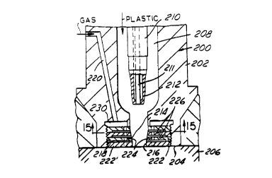
Other embodiments of the invention are shown
in Figures 14-17. In Figure 14, the bushing 200 has a
shank or body member 202 which has an end 204 which is
positioned flush with a wall of the mold 206 and corre-
S sponding mold cavity. The body member has a central
passageway 208 in which is positioned a movable gate pin
member 210. The pin member 210 and bushing body 202
have mating valve gate surfaces 212 and 214, respect-
ively. Axial movement of the pin member 210 by a motor
l0 mechanism (such as motor 24 shown in Figure 1) opens and
closes orifice 216 into the mold cavity and thus selec-
tively allows and prevents the flow of plastic material
into the mold cavity. The pin and orifice are shown
spaced apart in Figure 14 simply for ease of illustra-
15 tion; in actual practice, the pin and orifice are often
situated closer together and the vertical movement of
the pin to open and close the valve is on the order of
0.10 to 0.20 inches.
A cavity or threaded bore 218 is provided in
2o the end of the bushing body member 202. A gas passage-
way 220 provides a source of pressurized gas through the
bushing body and into the cavity 218. A plurality of
discs or washer members 222 - which are better shown in
Ffgure 15 (enlarged view) and in Figure 14A (crvss-
25 section) - are threadcdly secured in the cavity 218.
The discs or washers 222 are thin circular
plates, preferably of a metal material such as steel,
each of which have one or more openings or holes 224 and
a recess 226. A ridge of material 228 around the
30 perimeter or edge of the discs allows gas to freely flow
into and through the recesses 226. Also, as shown in
Figures 14 and 14A, the outermost disc or washer 222' is
preferably not provided with a corresponding recess or
CA 02258897 1998-12-21
WO 98/00278 . PCT/US97/10300
-19-
ridge, and also may or may not have any openings or
holes 224'. In operation, gas from passageway 220
enters chamber or manifold area 230 and passes through
openings 224 in the series of discs 224 and through the
recesses 226 into the central passageway 208. (If holes
224' are also provided, then some gas will also flow
directly into the mold cavity.)
The recesses 226 are preferably formed as thin
slits or slots between the stacked disc members 222 and
can be provided in one or both sides of each disc. The
thickness "T" of the recesses or slits is preferably the
same as the dimension specified above for the thin slits
or slots in the other embodiments.
The gas or fluid can be removed or exhausted
from the molded part through the same passageways in
which it was introduced into the mold cavity. Alterna-
tively, a central movable pin member 211 could be
provided in pin member 210 and either moved axially or
rotated around its axis in order to release the gas.
Other embodiments of disc or washer members
240 and 242 which can be utilized with the present
invention are shown in Figures 16 and 17. In these
embodiments, the central recesses or slots are divided
into several portions or areas by raised supporting ribs
or ridges 244 and 246. The ribs or ridges provide
additional supporting structure between adjacent disc
members in order to insure that the thin slits or slots
CA 02258897 1998-12-21
WO 98/00278 PCT/US97/10300
-20-
are maintained to prespecified dimensions. This allows
the desired amount of gas to flow through the standard
disc structure and assists the injection molding of the
plastic product in the mold cavity.
The ribs or ridges could be formed on the
washers by any conventional process. The ribs could be
embossed by a stamping or machine forming procedure.
The ribs also could be, formed by grinding or machining
away the areas between them. It is also possible to
provide washers with fluted or "wavy~~ profiles, whether
uniform or random.
The preferred embodiment of the invention at
this time is shown in Figure 20. A valve gate bushing
250 has a central plastic material passageway 252 and a
gas passageway 254 in the body or shank member 256. A
movable valve gate pin member 258 is located in the
passageway 252. The distal end 260 of the body member
has a cavity or bore 262. Two or more disc or washer
members 264 are positioned in the cavity 262. These
disc members 264 are similar to disc members 222 de-
scribed above, with at least one axial opening or hole
224 and a central recess 226, but without any external
threads. After the disc members 264 are positioned in
the cavity 262, a further disc member 266 is threadedly
secured into the outer end of the cavity 262 to hold the
discs 264 in place.
In order to axially align openings 224 in the
disc members 264 and/or to align them with the end of
passageway 254, any conventional alignment mechanism or
technique can be utilized, such as locating pin or rod
270. As should be clear from the above description of
these embodiments of the invention, the number of discs
CA 02258897 1998-12-21
WO 98/00278 FCT/US97/10300
-21-
or washer members to be utilized, the number of openings
or holes in each disc member, the type of recess or
ridges, and the presence or absence of a manifold cavity
between passageway 254 and the stacked disc members,
depends on the discrEtion and experience of the opera-
tor.
As with the other embodiments described above,
the slits or openings ,in or between the washers could
have, depending on the gas and process utilized, con-
verging, diverging or parallel surfaces, and dimensions
within the range of 0.0001 to 0.0100 inches. Also, the
washers could be formed by embossing, grinding or any
other conventional process.
It is also preferred to provided filters in
the gas or fluid inlet and outlet passageways in order
to provide and/or capture the gas in as clean or pure
form as possible. Such a filter is shown, for example, _
in Figure 20 and designated by the reference numeral
253. Also, for removal of the gas from the mold cavity,
the pin 258 could have a small diameter movable second
pin member (similar to pin 211 shown in Figure 14)
positioned inside it . The second pin member could be
adapted to be moved axially or rotated around its axis
in order to open a passageway for exhaust of the gas.
A still further embodiment of the invention is
shown in Figure 21. In this schematic representation,
a bushing 280 has a body member with a central passage-
way 284, and a tip member 286. The bushing preferably
is a valve gate bushing with a movable pin member 288
and gated orifice 290. Gas for the gas-assisted injec-
tion molding process is introduced into the central
passageway by adapter member or plug 292. The adapter
CA 02258897 1998-12-21
WO 98/00278 . PCT/LTS97/10300
-22-
member is connected to a primary gas passageway and
source of pressurized gas (not shown).
The adapter member has a plurality of small
diameter holes or channels 294 (two being shown by way
of example in Figure 21). Alternately, the channels 294
could be replaced by one annular channel in the adapter
292. The ends of the holes or channels have a size or
diameter substantially the same as the gas~introduction
apertures described above. In this regard, the adapter
292 can be provided with any of the various embodiments
and mechanisms described above with respect to allowing
entrance of the injection gas into the plastic flow or
mold cavity and at the same time preventing back flow,
clogging or plugging of the plastic into the openings.
The foregoing discussion discloses and
describes exemplary embodiments of the present inven-
tion. One skilled in the art will readily recognize
from such discussion, and from the accompanying drawings
and claims, that various changes, modification and
variations may be made therein without departing from
the spirit and scope of the invention as defined in the
following claims.