Language selection

Search

Patent 2259245 Summary

Third-party information liability

Some of the information on this Web page has been provided by external sources. The Government of Canada is not responsible for the accuracy, reliability or currency of the information supplied by external sources. Users wishing to rely upon this information should consult directly with the source of the information. Content provided by external sources is not subject to official languages, privacy and accessibility requirements.

Claims and Abstract availability

Any discrepancies in the text and image of the Claims and Abstract are due to differing posting times. Text of the Claims and Abstract are posted:

  • At the time the application is open to public inspection;
  • At the time of issue of the patent (grant).
(12) Patent: (11) CA 2259245
(54) English Title: SWING TAIL ASSEMBLY FOR MINER
(54) French Title: ENSEMBLE QUEUE PIVOTANTE DESTINE A UNE MACHINE D'EXPLOITATION MINIERE
Status: Expired
Bibliographic Data
(51) International Patent Classification (IPC):
  • E21C 35/20 (2006.01)
  • B65G 21/10 (2006.01)
  • B65G 47/64 (2006.01)
  • E21C 27/24 (2006.01)
(72) Inventors :
  • COLEMAN, GEORGE E. (United States of America)
  • WALKER, MICHAEL R. (United States of America)
(73) Owners :
  • ANGLO COAL PTY LTD (Australia)
(71) Applicants :
  • ARCH TECHNOLOGY CORPORATION (United States of America)
(74) Agent: NA
(74) Associate agent: NA
(45) Issued: 2002-10-08
(86) PCT Filing Date: 1997-11-12
(87) Open to Public Inspection: 1998-05-22
Examination requested: 1998-12-21
Availability of licence: N/A
(25) Language of filing: English

Patent Cooperation Treaty (PCT): Yes
(86) PCT Filing Number: PCT/US1997/021194
(87) International Publication Number: WO1998/021449
(85) National Entry: 1998-12-21

(30) Application Priority Data:
Application No. Country/Territory Date
08/747,446 United States of America 1996-11-12

Abstracts

English Abstract


A swing tail assembly rotates a swing tail conveyor (20) relative to a miner
conveyor (9) including a mounting assembly (38) mounting a drive arrangement
on a swing tail conveyor (20). The drive arrangement includes a hydraulic
motor (30), a differential planetary speed reducer (31) and a sprocket (33)
connected to said differential planetary speed reducer (31). A fixed pin/rack
arrangement (35) is connected to the fan section (10) of the miner conveyor
(9) and the sprocket (33) cooperates with the pin/rack arrangement (35) to
rotate the swing tail conveyor (20) relative to the miner conveyor (9).


French Abstract

Un ensemble queue pivotante fait tourner un convoyeur (20) à queue pivotante par rapport à un convoyeur (9) de machine d'exploitation minière comprenant un ensemble support (38) qui supporte un dispositif d'entraînement sur un convoyeur (20) à queue pivotante. Le dispositif d'entraînement comprend un moteur hydraulique (30), un réducteur (31) de vitesse à planétaire différentiel et une dent de pignon (33) connectée au réducteur (31) de vitesse à planétaire différentiel. Un dispositif (35) fixe broche/crémaillère est connecté à la partie ventilateur (10) du convoyeur (9) de machine d'exploitation minière et la dent de pignon (33) coopère avec le dispositif (35) broche/crémaillère pour faire tourner le convoyeur (20) à queue pivotante par rapport au convoyeur (9) de machine d'exploitation minière.

Claims

Note: Claims are shown in the official language in which they were submitted.


WHAT IS CLAIMED IS:

1. A swing tail assembly for rotating a swing
tail conveyor relative to a miner having a central conveyor
with an outby end having a fan section, said swing tail
assembly including:
a motor mounting assembly for mounting on a swing
tail conveyor;
a drive arrangement mounted on said motor
mounting assembly, said drive arrangement including a
hydraulic motor, a differential planetary speed reducer and
a sprocket operatively connected to said differential
planetary speed reducer; and
a fixed pin/rack arrangement adapted to be
mounted on a fan section of a miner conveyor,
whereby said sprocket cooperates with said fixed
pin/rack arrangement to rotate a swing tail conveyor
relative to a fan section of a miner conveyor.

2. A swing tail conveyor assembly as set forth
in claim 1 wherein said drive arrangement includes a
differential planetary speed reducer located between said
hydraulic motor and said sprocket and a drive shaft
operatively connecting said speed reducer to said sprocket
to rotate said sprocket.

3. A swing tail assembly for rotating a swing
tail conveyor relative to a miner having a central conveyor
with an outby end having a fan section, said swing tail
assembly including:
a motor mounting assembly for mounting on a swing
tail conveyor;
a drive arrangement mounted on said motor
mounting assembly, said drive arrangement including a
hydraulic motor, a differential planetary speed reducer and
a sprocket operatively connected to said differential
planetary speed reducer; and

-7-


a fixed pin/rack arrangement adapted to be
mounted on a fan section of a miner conveyor,
whereby said sprocket cooperates with said fixed
pin/rack arrangement to rotate a swing tail conveyor
relative to a fan section of a miner conveyor, and wherein
said pin/rack arrangement includes a plurality of spaced
substantially vertical pins arranged in an arc.

4. A swing tail conveyor assembly as set forth
in claim 3 wherein said pin/rack arrangement includes 26
spaced pins.

5. A swing tail conveyor assembly as set forth
in claim 3 wherein said plurality of pins is spaced
approximately two degrees apart.

6. A swing tail conveyor assembly as set forth
in claim 4 wherein each of said plurality of pins is spaced
approximately two degrees from each adjacent pin.

7. A swing tail conveyor assembly as set forth
in claim 1 wherein said pin/rack arrangement extends over
an arc of approximately 90°.

8. A continuous miner having an inby end and an
outby end, a rotary cutting drum adjustably mounted at said
inby end, a centrally located conveyor extending from said
inby end to said outby end, a fan section on said outby end
of said centrally located conveyor, a pin/rack arrangement
fixed to said fan section of said miner conveyor, a
substantially vertical pivot pin extending through said fan
section, a swing tail conveyor having an outby end and an
inby end pivotally mounted on said pivot pin for
articulated motion about said pivot pin and said miner
conveyor in a substantially horizontal plane, a swing tail
assembly for rotating said swing tail conveyor about said
pivot pin, said swing tail assembly including rotary drive

-8-


means mounted on said swing tail conveyor for contacting
said pin/rack arrangement on said fan section, and power
means for rotating said rotary drive means, whereby said
rotary drive means engages said fixed pin/rack arrangement
and rotation of said rotary drive means by said power means
rotates said swing tail conveyor about said pivot pin to
adjust the location of said outby end of said swing tail
conveyor in a horizontal plane.

9. A continuous miner as set forth in claim 8
wherein said power means includes a hydraulic motor, a
differential planetary speed reducer operatively connected
to said hydraulic motor and said rotary drive means is
operatively connected to said differential planetary speed
reducer to rotate said rotary drive means.

10. A continuous miner as set forth in claim 9
wherein said rotary drive means is a sprocket.

11. A continuous miner, comprising:
an inby end and an outby end;
a rotary cutting drum adjustably mounted at said
inby end;
a centrally located conveyor extending from said
inby end to said outby end;
a fan section on said outby end of said centrally
located conveyor;
a pin/rack arrangement fixed to said fan section
of said miner conveyor;
a substantially vertical pivot pin extending
through said fan section;
a swing tail conveyor having an outby end and an
inby end pivotally mounted on said pivot pin for
articulated motion about said pivot pin and said miner
conveyor in a substantially horizontal plane; and
a swing tail assembly for rotating said swing
tail conveyor about said pivot pin, said swing tail

-9-


assembly including rotary drive means mounted on said swing
tail conveyor for contacting said pin/rack arrangement on
said fan section, and power means for rotating said rotary
drive means,
whereby said rotary drive means engages said
fixed pin/rack arrangement and rotation of said rotary
drive means by said power means rotates said swing tail
conveyor about said pivot pin to adjust the location of
said outby end of said swing tail conveyor in a horizontal
plane, and
wherein said pin/rack arrangement includes a
plurality of spaced substantially vertical pins arranged in
an arc.

12. A continuous miner as set forth in claim 11
wherein said pin/rack arrangement includes 26 spaced pins.

13. A continuous miner as set forth in claim 11
wherein said plurality of pins is spaced approximately two
degrees apart.

14. A continuous miner as set forth in claim 12
wherein each of said plurality of pins is spaced
approximately two degrees from each adjacent pin.

15. A continuous miner as set forth in claim 8
wherein said pin/rack arrangement extends over an arc of
approximately 90° of the periphery of said fan section of
said miner conveyor.

16. A swing tail assembly for rotating a swing
tail conveyor relative to a miner having a central conveyor
with an outby end having a fan section, said swing tail
assembly including:
a mounting assembly for mounting said swing tail
assembly on a swing tail conveyor;


-10-


a drive arrangement on said mounting assembly,
said drive arrangement including a hydraulic motor and a
sprocket; and
a fixed pin/rack arrangement,
whereby said sprocket cooperates with said fixed
pin/rack arrangement for rotating the swing tail conveyor
relative to the miner conveyor.

17. A swing tail conveyor assembly as set forth
in claim 16 wherein said pin/rack arrangement is adapted to
be connected to the fan section of the miner conveyor.

18. A swing tail conveyor assembly as set forth
in claim 16 wherein said pin/rack arrangement includes a
plurality of spaced pins configured to engage said
sprocket.

19. A swing tail conveyor assembly as set forth
in claim 18 wherein said pins are arranged in an arc.
-10a-

Description

Note: Descriptions are shown in the official language in which they were submitted.


CA 022~924~ 1998-12-21

WO 98/21449 - PCT/US97/21194


SWING TAIL ASSEMBLY FOR MINE~
~ACKGROUND OF THE INVENTION
1. Field of the Invention
The invention relates generally to a continuous
miner having a.n articulated swing tail conveyor pivotally
connected to the outby end and, more particularly, to a
swing tail ass,embly mounted at the outby end of the miner
for adiusting the angular position of the swing tail
conveyor relative to the longitl~;n~l axis of the miner.
The invention has a variety of applications
wherever loose material is transferred from a conveyor on
a machine such as a cutting machine onto a conveyor on
another machine or onto a haulage conveyor. The invention
is described hereinafter in connection with a drum type
continuous miner but i5 not limited to use with such a
machine.
Briefly, this type of miner consists of a frame
mounted on crawlers for tr~mm; n~ along a mine floor and for
sumping the cutting drum into a mine face. The cutting
drum has a plurality of cutting elements removably mounted
thereon and is mounted for rotation on its transverse axis
at the inby end of the miner frame. The drum is rotatably
mounted on the free ends of parallel support arms which are
pivotally mou;nted on the frame. The cutting elements on
the drum cut the full height of the coal seam between the
floor and the roof by pivoting the arms relative to the
frame to raise and lower the rotary drum.
The miner includes a gathering pan located at the
front of the frame below the cutting drum which collects
the mined material. Gathering heads are mounted above the
pan to direct the loose mined material onto a centrally
located conveyor extending rearwardly from the inby end of
the miner to the outby end of the miner. The loose
material is t:ransferred to a swing tail conveyor at the
outby end of the central conveyor so that it can be


. , .

CA 022~924~ 1998-12-21

~ W098/2~449 PCT~S97/21194


directed to other haulage equipment to move it to either
another location into or out of the mine.
2. Summarv of the Invention
The invention is a swing tail assembly for a
swing tail conveyor which is in operative communication
with the outby end of the central conveyor on the miner.
The swing tail conveyor is pivoted about a pin to permit
the free end of the swing tail conveyor to move relative to
the longitudinal axis of the miner. The pivot pin has a
substantially vertical axis so that the outlet end of the
swing tail conveyor can be ad~usted through an arc relative
to the outby end of the miner to direct loose material from
the miner conveyor onto the conveyor on another machine or
onto a haulage system located in the mine.
The swing tail assembly of the invention is
inexpensive and mechanically simple and requires minimal
maintenance. The swing tail assembly consists of a
stationary pin/rack arrangement on the fan section of the
outby end of the miner conveyor and a rotary drive pinion
on the inby end of the swing tail conveyor which cooperates
with the pin/rack arrangement to pivot the swing tail
conveyor about the pivot pin relative to the outby end of
the miner conveyor.
A complete understanding of the invention will be
obtained frorn the following description when taken in
connection with the accompanying drawing figures wherein
like reference characters identify like parts throughout.
E,RIEF DESCRIPTION OF THE DRAWINGS
Fig. l is a side elevation of a continuous miner
having a swing tail conveyor mounted thereon;
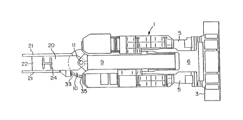
Fig. 2 is a plan view of the continuous miner
shown in Fig. l;
Fig. 3 is a plan view of the fan section of the
outby end of the miner conveyor and the inby end of the
swing tail conveyor pivotally connected thereto;

CA 022~924~ 1998-12-21

WOg8/21449 PCT~S97/21194


Fig. 4 is a side elevation of the swing tail
assembly;
Fig. 5 is a plan view of the swing tail assembly
and
Fig. 6 is a side elevation of the drive pinion of
the swing tail assembly.
DESCL~IPTION OF THE PREFERRED EMBODIMENT
With reference to Figs. l and 2 of the drawings,
the continuous miner l is mounted on crawlers 2 and has a
horizontal, rotary cutting drum 3 at its forward end with
cutting bits thereon (not shown). The drum is mounted on
the ends of a pair of spaced arms 5 which are pivotally
mounted on the machine frame for movement in an arc to
raise and lower the drum 3 to cut coal from the face
between the f:Loor and the roof of the mine. A gathering
pan 6 is located below and slightly behind the drum 3 to
collect the coal which is mined from the face. The pan 6
will have gathering arms or discs mounted therein which
move the mined coal centrally and rearwardly to the inby
end of a cent:ral conveyor 9 which is located between the
crawlers 2 and extends from the pan 6 to the outby end of
the miner l. The outby end of the conveyor 9 is formed
with a fan section l0 and the swing tail conveyor 20 is
pivotally mounted on the fan section l0 by a vertical pivot
pin ll which extends through the fan section l0 of the
miner conveyor 9 and through the inby end of the swing tail
conveyor 20 to connect the two for relative arcuate
movement of the swing tail conveyor relative to the
longitudinal axis of the miner.
As shown in Figs. 3-6 of the drawings, the swing
tail conveyor consists of a frame having spaced side
members 21 and a bottom plate 22 between the side members.
A continuous chain conveyor 24 extends between the side
members 21 alons the length of the swing tail conveyor.
The central conveyor 9 on the miner l moves coal rearwardly

CA 022~924~ 1998-12-21

WO98/21449 PCT~S97/21194


from the gathering pan 6 onto the inby end of the swing
tail conveyor from where it is transported rearwardly away
from the miner to another haulage system to move it to
another location in the mine or out of the mine. The
pivotal adjustment of the outby end of the swing tail
conveyor makes it possible to deposit mined coal at
locations away from the outby end of the miner 1 which are
not longitudinally aligned with the miner conveyor. Thus,
the swing tail conveyor pivots about the pivot pin 11
through an arc: of approximately 45~ on each side of the
longitl~in~l central axis of the miner conveyor 9 to adjust
the location cf the outby end of the swing tail conveyor
relative to the outby end of the miner conveyor.
The swing tail assembly pivots the swing tail
conveyor about: the pivot pin 11 for articulation in a
substantially horizontal plane. The swing tail assembly is
a compact arrangement which replaces the traditional prior
art hydraulic cylinder used to pivot the swing tail
conveyor. The elimination of the hydraulic cylinder
permits the miner to operate in a more limited space and
with a smoother articulation motion of the swing tail
conveyor than is possible using the prior art hydraulic
cylinder to adjust the swing tail conveyor.
The swing tail assembly shown in Figs. 3-6 of the
drawings includes a hydraulic motor 30 having a vertical
drive shaft, a differential planetary speed reducer 31 and
a sprocket 33, all of which are mounted on an adjustable
motor mounting assembly 38 mounted on the inby end of the
swing tail conveyor 20. A sprocket retainer cap 34 is
fixed on the lower end of the drive shaft of the
differential planetary speed reducer 31 to hold the
sprocket 33 in place on the shaft. The sprocket 33 is
fixed to rot'~te with the shaft of the differential
planetary spee~ reducer 31 by keys and/or set screws. A

CA 022~924~ 1998-12-21

WO98/21449 PCT~S97/21194


pin/rack arrangement 35 is attached to the fan section lO
of the miner conveyor 9.
The pin/rack arrangement 35 shown in the drawings
has 26 substantially vertical pins 36 spaced approximately
two radial degrees apart extending in an arc of
approximately 90~ of a circle on the fan section of the
miner conveyor lO. Thus, rotation of the sprocket 33 will
cause relative rotation of the outby end of the swing tail
conveyor through an arc of approximately 45~ in each
direction relative to the longitudinal central axis of the
miner. It will be understood by those skilled in the art
that the number of pins and the degrees of spacing between
adjacent pins will vary in accordance with the number of
degrees in the arc through which the swing tail conveyor is
to rotate.
The hydraulic motor 30 is a low speed, high
tor~ue motor which powers the differential planetary speed
reducer 3l. The speed reducer drives a drive shaft which
carries the sprocket 33. The sprocket teeth travel around
the stationar~ pin/rack arrangement 35 to pivot the swing
tail conveyor 20 about the pivot pin ll. The swing tail
assembly utilizes the same hydraulic power supply and
return hoses that are present on a miner having a hydraulic
cylinder to pivot the swing tail conveyor and, hence,
redesign of the hydraulic system is not required to install
a swing tail assembly according to the invention on a
miner. A direct interchange of the hydraulic motor may be
made for the hydraulic cylinder. If desired, a flow
control valve may be connected in the hydraulic system to
vary the speecl of the hydraulic motor to adjust the speed
of rotation of the swing tail conveyor about the pivot pin
11 .
The planetary speed reducer 3l is mounted on a motor
mounting asserrlbly 38 which is adjustably mounted on the
inby end of rhe swing tail conveyor 20 by bolts 39 to

CA 022~924~ 1998-12-21

- WO98/21449 PCT~S97/21194


locate the sprocket relative to the pin/rack arrangement 35
on the fan section lO of the central miner conveyor 9. The
adjustable mounting of the motor mounting assembly 38
permits the sprocket 33 to be accurately located relative
to the pin/rack arrangement 35 on the fan section lO.
It will be understood by those skilled in the art
that the swing tail assembly provides an efficient and
relatively inexpensive arrangement to pivot the swing tail
conveyor 20 about the pivot pin ll. The assembly requires
a minimum of space so that the assembly does not extend
laterally beyond the dimensions of the fan section of the
miner conveyor and interfere with the operation of the
miner. The swing tail assembly provides a substantial
degree of articulated movement of the swing tail conveyor
in the horizontal plane.
In t:he foregoing description, it will be readily
appreciated by those skilled in the art that modifications
may be made t:o the invention without departing from the
concepts disclosed herein. Such modifications are to be
considered as included within the following claims, unless
the claims by their language expressly state otherwise.
Accordingly, the particular embodiments are illustrative
only and are not limiting as to the scope of the invention
which is to be given the full breadth of the appended
claims and any and all equivalents thereof.

Representative Drawing
A single figure which represents the drawing illustrating the invention.
Administrative Status

For a clearer understanding of the status of the application/patent presented on this page, the site Disclaimer , as well as the definitions for Patent , Administrative Status , Maintenance Fee  and Payment History  should be consulted.

Administrative Status

Title Date
Forecasted Issue Date 2002-10-08
(86) PCT Filing Date 1997-11-12
(87) PCT Publication Date 1998-05-22
(85) National Entry 1998-12-21
Examination Requested 1998-12-21
(45) Issued 2002-10-08
Expired 2017-11-14

Abandonment History

There is no abandonment history.

Payment History

Fee Type Anniversary Year Due Date Amount Paid Paid Date
Request for Examination $400.00 1998-12-21
Registration of a document - section 124 $100.00 1998-12-21
Application Fee $300.00 1998-12-21
Maintenance Fee - Application - New Act 2 1999-11-12 $100.00 1998-12-21
Maintenance Fee - Application - New Act 3 2000-11-13 $100.00 2000-08-17
Maintenance Fee - Application - New Act 4 2001-11-13 $100.00 2001-11-01
Final Fee $300.00 2002-07-25
Maintenance Fee - Patent - New Act 5 2002-11-12 $150.00 2002-11-05
Registration of a document - section 124 $100.00 2003-04-02
Maintenance Fee - Patent - New Act 6 2003-11-12 $150.00 2003-11-12
Maintenance Fee - Patent - New Act 7 2004-11-12 $200.00 2004-11-12
Maintenance Fee - Patent - New Act 8 2005-11-14 $200.00 2005-11-14
Maintenance Fee - Patent - New Act 9 2006-11-14 $200.00 2006-11-10
Maintenance Fee - Patent - New Act 10 2007-11-12 $250.00 2007-10-17
Maintenance Fee - Patent - New Act 11 2008-11-12 $250.00 2008-10-17
Registration of a document - section 124 $100.00 2008-12-30
Maintenance Fee - Patent - New Act 12 2009-11-12 $450.00 2009-12-04
Maintenance Fee - Patent - New Act 13 2010-11-12 $250.00 2010-10-28
Maintenance Fee - Patent - New Act 14 2011-11-14 $250.00 2011-11-14
Maintenance Fee - Patent - New Act 15 2012-11-13 $450.00 2012-10-31
Maintenance Fee - Patent - New Act 16 2013-11-12 $450.00 2013-11-04
Maintenance Fee - Patent - New Act 17 2014-11-12 $450.00 2014-11-03
Maintenance Fee - Patent - New Act 18 2015-11-12 $450.00 2015-11-02
Maintenance Fee - Patent - New Act 19 2016-11-14 $450.00 2016-10-31
Owners on Record

Note: Records showing the ownership history in alphabetical order.

Current Owners on Record
ANGLO COAL PTY LTD
Past Owners on Record
ARCH TECHNOLOGY CORPORATION
ARCHVEYOR PTY LIMITED
COLEMAN, GEORGE E.
WALKER, MICHAEL R.
Past Owners that do not appear in the "Owners on Record" listing will appear in other documentation within the application.
Documents

To view selected files, please enter reCAPTCHA code :


To view images, click a link in the Document Description column. To download the documents, select one or more checkboxes in the first column and then click the "Download Selected in PDF format (Zip Archive)" or the "Download Selected as Single PDF" button.

List of published and non-published patent-specific documents on the CPD .

If you have any difficulty accessing content, you can call the Client Service Centre at 1-866-997-1936 or send them an e-mail at CIPO Client Service Centre.


Document
Description 
Date
(yyyy-mm-dd) 
Number of pages   Size of Image (KB) 
Drawings 1998-12-21 3 77
Abstract 1998-12-21 1 49
Description 1998-12-21 6 285
Claims 1998-12-21 5 203
Cover Page 1999-03-19 1 49
Cover Page 2002-09-04 1 40
Representative Drawing 1999-03-19 1 8
Fees 2001-11-01 1 36
Correspondence 2002-07-25 1 37
Assignment 2003-04-02 8 315
Assignment 2003-07-17 2 67
Fees 2003-11-12 1 36
Correspondence 2003-09-24 1 12
Assignment 1998-12-21 10 503
Fees 2002-11-05 1 38
Fees 2000-08-17 1 35
PCT 1998-12-21 10 363
Fees 2004-11-12 1 29
Fees 2005-11-14 1 31
Assignment 2008-12-30 3 109
Fees 2011-11-14 1 28
Correspondence 2016-11-03 3 122
Office Letter 2016-11-28 138 4,360