Note: Descriptions are shown in the official language in which they were submitted.
CA 022~9266 1998-12-23
WO 98/00288 PCT/US97/11515
Title: CUSHIONING CONVERSION MACHINE
TECHNICAL FIELD
This invention relates generally to a safety device and, more particularly, to
a safety device for proL~ lg the hands of an opel~to~ of a cushion conversion
",~rhi"~ during a cutting operation.
BACKGROUND OF THE INVENTION
In the process of shipping an item from one location to another, a protective
p~ck~ing material is typically placed in the shipping case, or box, to fill any voids
and/or to cushion the item during the shipping process. Some conventional
~rot~.;live p~cL-~ging materials are plastic foam peanuts and plastic bubble pack.
While these conventional plastic materials seem to pell~ adequately as
cushioning products, they are not without disadvantages. Perhaps the most serious
drawback of plastic bubble wrap and/or plastic foam peanuts is their effect on our
environnlenl. Quite simply, these plastic parJr~ging materials are not biodegradable
and thus they cannot avoid further multiplying our planet's already critical waste
disposal problems. The non-biodegradability of these ~e~ging materials has
become increasingly important in light of many industries adopting more
progressive policies in terms of environment~l responsibility.
The foregoing and other disadvantages of conventional plastic pack~ing
materials have made paper plote~;live p~ck~ing material a very popular ~ltern~tive.
Paper is biodegradable, recyclable and renewable, making it an envilolllllell~lly
responsible choice for conscientious industries. Furthermore, paper protective
duMage material is particularly advantageous for use with particle-sensitive
merch~n-lice, as its clean, dust-free surface is resistant to electrostatic buildup.
While paper in sheet form could possibly be used as a protective park~ging
material, it is usually preferable to convert the sheets of paper into a pad-like or
other relatively low density dunnage product. This conversion may be
accomplished by a cushioning conversion m~rhinr, such as those disclosed in
commonly ~csignPd U.S. Patent Nos. 4,968,291 and 5,123,889. The therein
CA 022S9266 1998-12-23
dis~losel C~~ n~ n~r~;iorl m~c'~ e~ ~.e '~t~ r'~
p~p~r irl rr.ulti-r iy l'or;~ ~nt~J 1 ?ad-iL~e d~ e prcduct h~g o. ~O~ a~ l r
din~ ~iiiGW-'!;ke porti~n~ rh.,~ ~re cur~ ected lo~eth~ ~o~ t t~he~l c.r.~l
pol~tion~)~the~ro~lct Ihe STCCI~II'~ti~ r?ferab~, CCrSiS~O~ OGr t~-C~
super~rnp~d ~bs GI ~ TS O~blOCegTa_~bi ~ r~C~rCl~ d ;~ t~-rol~Lnd
~ft paper or t~ie LYe ;~ o~o ~ holl~w e~ li~drical m~e A T!~ t~cn ~ r~.i!
cf ~ p~er. whieh i~ approx~itel~.r ~ f~-t 1l3rx, u .ii weigh ~co... ~ p~
~ill ~rc v~d~ shion~g e~l~l to ~prnxi~.~tc-lJ~ ur fifteen cl!blc .~ lqt bu of p~ ic
foa~l Fea;lu,s ~hile a. rhe s~rne r~e re~u~ri~CT ~ess t~ 3ne-~hi~ie~ rhe sTo~,e
s ~
~ e~nfically~ se rn~c,~es con~ert tke stc_k .~ r ~l ir.~ ~ co~r~o~ s~.p
h~ira 13.t~1 Filiow~ )rtions ~ep~[~ by a t~lrn cen~l ~d. T~;is ~
cor.ne~-~d or e~ .ed ~ n~ the ce2t al ~~nd to ,~ coin~d strip ~ ic.~ Is at~ ;er ~ or
C~lt into ~e ~ions or a t~esired Jer.sr.h. Tl.e cut sections c~ch inc,u~e l~. -;3l p~lo~
I~ Fc~cns ;e~ar~ted b~ ~in ce~tr~L banCL .~Ld prG~i~e 3n e~.cellent re;~.~el~- 1O~J
'erL,Lt~ ?~d-like ~.oduct which may be ~sed ~n F11C~ ~t' ~ 'eLL-~LO-a~ ;;!St-lC
Drot~ p~c'.~. cinS ,naterizl.
.4~1 XSUir ~f ~h.e :~uc~nes~ of ~he atr.p rraàu.~d by a ~,~UshiGL~ ~r C Or.~erS.~:
m~-1n;~. SUCil as ~hc~e describ~ ~bo~e, tlle se~.ren~ ~ or cu~ng ~crion ~'lSt ~f~e~
~0 quite L' ~Ce~ . for e~ ple, emFloyin~-r ~ heav~J ~nd re~ ly sh2~ d~ er ~la~le ~r
blad~ surfzce~ dequatel~rc~tthe ~ int~ ;e~tions of rhe l~ dle~r~h. r..e
t~minC~ ~r,d ~eque~cy o~ the cuts is o~Len vari,~ie ~ld of~en Uhe -~c p~od;l~t e~n~es ~'
m the cus.~ion con~e~sior. mil~hirle a~ 3 I~ly l~pid r~te. Il~is~ cou~!~d ~ h th~
additional facl that *e paper m~y ~ome~imes b-veom~; amu~e(i ;n ~he c~lr~in J
~5 m~ch~ m aLd cutput of th~ m~C~L nt~ k.e the c~ mec~l~nism ~ o~ra~ion ~n
o~ s~f~ oncer~ L-O~ a cushion~r~ con~ersion m ~rh .n~?
~ IanY present cllshi oning c~Lver~ion macl~rL~s i nclude ~ plur31:~ o~ safety
fe3t~-es tO prolcct the hands ~r ~n ~pe~ator during ~ c~ .ng o~rari~n. .uch ~s for
~pl;~, ~e uso of m~uple, sDace~ a~ti-~e dcw~ s~i~hes ~lecunc~ r~3~s,~c.
~0 Also, W O-A-~C/~8-~7k dlsclosesa GU~On1~ eo~/e~sion m~ch~eh~v~ an3ccess
ass~mbl~ ~comprised of tw-, s~iveling ~vesj ~fhich is ~losed t~ prevcn~ accecs to 1;he
AA~r.i\i~D S'rlEET
CA 02259266 1998-12-23
~'.~n~ ~s~ J~ernel~a,i~iS ~ S ~ ?~ r~ (_
r~n-~.s,o~ m~ es~ -n~ ~rcl~b~[i~u~s~'e~ c-st
oper~lors~fe~.
~r~ C
CA 02259266 1998-12-23
SU~ RY O~ THF L~E~IO.Y
The pr~se~t in~rention provides for improved i~ety when usin, cushicn
conversion rnachines. Such improved safety i~ achie~ed b~ pre~-ent~ng an oper~or's
body parts (genel~lly fingers, haI~ds a~ ~s) from cornino int~ cont c. ulrith t~e
S ~ov~ c~3 ~l~de or bl~des of ~ cu~hiot!ing ~n~ ersion m~rhTne ~s th~ operatot
collects tha output from t~.e ma~hine.
In accorda~ce ~ith one aspecl or' the present inve~t~cn, ~ s~'ety OUtPUI chute
for a cushioning coc~ ion rn~ ine incl~ chllte haYing an input en~i ~d an
ou~put end~ th~ input ~nd in~]l1/lin~ an op2ning for recei~ g 3 fle~c~ble cl~cniorl~ng
I O prod~lct from arl o~tkt of thc cushio~ing con~.~ersion m~t~hinP and a pl~lity of
rolle~s sihlat~d in~e the chu~e, the roll~rs being oriented sueh that The lle~{ible
cusllio~ing product must follow a Aon-linear path from the inpul end of th~ chu~e ~o
the output end of the chu~ lo inhibil acces~ to the input end ~f the chute &om the
output end thereo~
In accorda~ce ~ith a~cther aspe~t of the in~e~orl, a sat'e~ output chute for a
cushio~ conv~rsion ~rhin~ incll~de~ ~ chute ha~ ~ i~lpUt end and ~n outpurt
end, the inpu~ end iIlciuairlg am cpe~ for recei~in~ a ~.lshionin~ product f~om an
outlet of rh~ cushioning conversion m:~rhine, ~nd a rotating ~ssembiy disp~s~d within
the chute. The rot3~ng assem~ly includes ~ plurality of r~ Yt~n~ling vanes
~O disposed o~ a rot3table shi~ which l~te~ally tr rcrses the chute The ~ s com:act
the cush~o~g product a~nd rotate to pe~m~t moYeme~t of the cusnio~i~g product
~hrou~h the chute while inhibi~in~ ~ccess to the inpu~ end cf the chuee ~om the ~utput
end the~eof.
In accordanc~ ~ith yet anolheT aspect of the in~ tia~ ~ saf~tv Cll~pUt chutc
tor a cn~hinnin ~ ~on~,~ersi~n m~c~ne include~ ~ chute hav n~ ~n input e~d and an
output end, the input end inelu-lin~ a~ o~ g; for ~P~ei~ing ~ cl~hi ~min5 prcd~ct
~om an cutlet of the cushion~ng conversio~ mq~hitlP, and a sensor ~r serlsing the
presence of a foreign object in the outp~t chute ~d g~P~nng a signal for
A~/lENO~D S~IEET
~ CA 02259266 1998-12-23- -
communicancn lo rhe cushioning c~ ersion machine in accord~nc~ uith suc~
3~ns 1 n g,
In ~ordance ~I-iTh a ~ilrther aspe~t of Ihe ir.ve~ion. 3 ~3fery 0utpuLcllUte
~nr ~ cushio~r.g co~,ersion rn~hine ~ncludes a chute ha~ing armnpul en~ and an
outpn~ end, the input end including a~ ~per~ing for recei~,~ a cushio~ng product~om an outlet of t~le c~1chinnill~ conl,ersion ~ e, a shield disposed with ~h~ c;~lute
hav~ an opcn posilion and a closed position, an acr~tor me~h~ni Sm for mo~-ing ~.e
shield between ope~ ~d cJosed pOsit;o~ a de~ector mech~!icm mou~ o 2
wall of the chute îor det~c-ing whe~u~ler the shicld is in an iIrLproper ~osition mdica~e
L O of the presence of a fGrei,~n obj~c~ in the ohute in ~ dition to the euchionin ~ prC duct
In ~ccor1~nc~ with ~ s~ill fi~rther aspect of t~le ~nvention, a safety o~tput chute
for ~ ~ushion~n~ co~ve~sion m~rhinP in~!u~Pe ~ ohllte havi~n 3n input end ineludillg
a~ ope~ing for recei-~irLg ~ cu~hioning prod~et from i~n outlet ~f .he cu~hionir~
e~nversion m:~rhin~ hu~e including ~ hinged .o~er, and ~ sliding dcor fo-
~elecuvel~ o~Lg the ope~ing w~n th~ _ov2r iS open ~na pemLittirL~ passage
thr(~U~l the opening when the ~er LS ciosed.
ccor~ce with a~ e~en ~ er a.r~ct o f the inventiorL ~ ~afety OutpUl
chute for 1 cushi~ning con~ersion m~rhin~ inrl rc ~ chule ha-~g an i~DUt e~d ~ndan output en~, the ~nput en~ inr.~ in~ ~ openinë for .ecei-in3 1 Qe~ible cll~hir:ni~
~0 produc~ firom ~n outlet of the cushion~lg conversion mArhi r e; ~nd ~ pl-~lity of
axially spaced kinged Pipm~nte s~ nti~l~v preventin~ ress ;hough t~e chute from
~eo ~ Ul end tow~s ~e input end.
In accordance Wit~L ,mother ~spect of the in~emLon, a safet~ output chute for a
c~l~hinnin~ ccnv,ersion m~-hine includes a chute ~av~g an i~pu~ end and ~ our~ut~nd, the ~put en~ inrl~l~in~ an open~.~ for receivillg a cushionin& product f~om 3n
outlet of the cushia~ conversion machi~e; a s~ield partially within ~e chu~e hav~ng
~1 open pusition ~d ~ closed pasitiou, I:he chule ex~endi~g outside of the chute to
contact and ~o deflc~t thc c~!shio~g product outsidc of t~ chute ~,v~len in the c~osed
AP~IEN~ED S~IEET
. ~. ,. . ~ . ,
CA 02259266 1998-12-23
posi~on. and ~n actud~n~ mechan~sm f~r rno~ rhe shield b~ n ~e o~en n~
elosed positions.
Ln accor~nce ~ith si~ ano~er ~pect o~ ~,c in-'en~o~ ~af~h~ou~ut ~h~.e
~or~cushio~ing conversion m~hine includes a ehu~e having ;m irput end and an
S outpUt end, the ~put ~nd iIlcludin~ an opelling fol rec~i~a ~ cush~orlir.~, prGduct
*om an outlc~ of *.e cushioD~T conver~io~ mac~ e, a sing~e snield d~sposed wi~bi~
~he chute havir~ an o~e~ posi~io~ ~d d clo5ed pos~ti~n. Th~ ~nield is ldaoted toc~n~ct the cu3hion~g product ~enerall~ ~!o~g a r~dtlced portion of its surface ~h~
~n a c1oscd po~i~on, ~d 3n ~c~zt7n~ C:~ni~m for moving t~e shield bem-een the
oper. and ~losed ~osition3. llle ~hiel~ prefer~blv com~rises a distal pomo~ P~t~~n~iin~r
ar an ar.~le rela~ive ~ ~.e ~st of the shicid. ~d Thii ~stal p~l~ou CorlL:lcts the
cus~ioning ~roduct gener~lly alon~ the reduced portion of its surf~ce. rne
aforemermoned ~fe~rlres and ~cher ~spe~ of the present invention ~re d~cribe~ inmore derail ~n +he 1ct~;ilcd dcscrip~on and ~.e ~ceo~panyin~ dr~wings which follGw.
l F ~5T
CA 022~9266 1998-12-23
w 098/00288 PCTrUS97/11515
BRIEF DESCRIPTION OFTHE DRAWINGS
Figure 1 is a top view of a cushioning conversion mn~hinP including a safety
output chute inr.ln-ling a rotating vane assembly in acco~dal~ce with one embodiment
of the present invention;
S Figure 2 is a partial side elevatiollal of the cnchioning conversion m~chinP
and the safety output chute of Figure 1;
Figure 3 is front elevational view of the safety output chute looking into the
opening of the chute;
Figure 4 is a partial top view of an alternate embodiment of the rotating vane
assembly inrluding axially continuous vanes;
Figure 5 is a partial top view of a cushioning conversion m~r~in~ and the
rotating vane assembly powered by the cushioning conversion m~rhin~;
Figure 6 is a top view of a cushioning conversion machine and an alternate
embodiment of a safety output chute including an output sensor;
Figure 7 is a front elevational view of the safety output chute of Figure 6;
Figure 8 is a top view of a cushioning conversion m~r.llinP and an alternate
embodiment of a safety output chute including a labyrinth of rollers;
Figure 9 is a side elevational view of the cushioning conversion machine and
safety output chute of Figure 8;
Figure 10 is a front elevational view of the safety output chute of Figure 8;
Figure 11 is a front elevational view of an alternate embodiment of a safety
output chute including a movable shield;
Figure 12 is a side elevational view of the safety output chute of Figure 11;
Figure 13 is a top view of a cushioning conversion machine employing an
alternate embodiment of a safety output chute having an access cover;
Figure 14 is a side elevational view of the cushioning conversion m~rhinP
and safety output chute of Figure 13;
Figures 15 and 16 are end views of the closure assembly in a closed position
and an open position, respectively, for the safety output chute of Figure 13;
Figure 17 is a front elevational view of a cushioning conversion m~rhinP in
an altern~te embodiment of a safety output chute having an access cover;
CA 022~9266 1998-12-23
WO 98/00288 PCT/US97/llS15
Figure 18 is a side elevational view of a cushioning co~ ion m~chinr and
safety output chute of Figure 17;
Figures 19 and 20 are views of a closure assembly with the access cover of
the safety output chute closed and open, respectively;
Figure 21 is a cutaway elevation view of a safety output chute according to
an altçrn~ embodiment of the present invention;
Figure 22 is a cutaway top view of the safety output chute of Figure 21;
Figure 23 is a close-up view of the flaps which constitute a part of the chute
guide for a safety output chute;
Figure 24 is a cutaway elevation view of the safety output chute of Figure 21
with a cushioning product in the chute;
Figure 25 is a cutaway elevation view of the safety chute of Figure 21 with
the top tray elevated;
Figure 26 is a partial cross-sectional view of a safety output chute with a
powered chute guard in a closed position;
Figure 27 is a partial cross-section~l view of the safety output chute of
Figure 26 with the powered chute guard in an open position;
Figure 28 is an alternate embodiment of a safety output chute with a
powered chute guard; and
Figure 29 is a further alternate embodiment of a safety output chute with a
powered chute guard.
DETAILED DESCRIPrION OF THE INVENTION
Referring now to the drawings in detail and initially to Figures 1 and 2,
there is shown a cushioning conversion m~clline 10 for creating low density
cushioning pads in~lnrling a safety output chute 12 located at the dowlLsLl,,alll end
14 of the m~ inP for providing the pads formed by the cushioning m~t~.hinr to anoperator in a safe and effective manner.
The m~rllin~? 10 includes a frame 16 to which are mounted a supply
assembly 18 at the uy~lcalll end 20 of the frame for supplying stock material to be
converted into a cushioning product, a conversion assembly 22 for converting thestock material into a continuous strip of cushioning product and a severing or
.. ... ..
CA 022~9266 1998-12-23
wo ~ 8 Pcrluss7lllsl5
cutting assembly 24 located generally between the conversion assembly and the
safety output chute 12 at the do~hllsLI~ end 14 of the frame for severing the strip
into cushioning pads of the desired length. (The terms "upstream" and
"down~L,~alll" in this context are characteristic of the direction of flow of the stock
material through the m~rhin~ 10.)
The stock supply assembly 18 preferably includes a shaft or axle 28 for
supporting a roll of sheet-like stock material (not shown) and a llulllb~r of rollers 30
for providing the stock material to the conversion assembly 22. The stock material
may consist of three ~u~ lilllposed webs of biodegradable, recyclable and reusable
thirty-pound Kraft paper or the like rolled onto a hollow cylindrical tube. The
conversion assembly 22 includes a forming assembly 32, such as a coope~dtillg
three-~limP-n~ional wire former 34 and converging chute 36 as is shown in Figure 1,
and a feed assembly 38 including a pair of gears 40 for pulling the stock material
through the forming assembly and feeding it through an outlet 42 to the severing or
cutting assembly 24 and the safety chute 12. The cutting assembly 24 is positioned
adjacent the m~rhinl- outlet 42 and may include one or more blades 44 or other
means acting to sever the continuous strip of padding ell.~rgillg from the outlet at
the a~ )pliate times. The cutting assembly 24 further includes a motor, air
cylinder or solenoid 46 powering the blade 44 or other severing means through a
shaft linkage assembly 50. The area of the cutting operation is confined within an
enclosure 52 mounted to an ~lpst~n-ling frame portion 54 including the m~rhin
outlet 42 and ~u~pu~Led upon a frame extension 56.
Control of the cushioning conversion m~chinP 10 in general and of the
conversion assembly 22 and cutting assembly 24 in particular is preferably
accomplished and coordinated through the use of a process controller (shown
schem~tic~lly at 51) as described more fully in copending U.S. Patent Application
Serial No. 08/279,149 which is incorporated herein in its entirety by this reference.
The process controller 51 may co"",~ ic~te with the various elements and
assemblies of the cushioning conversion m:~rhin~ 10 and peripheral components
through a variety of conventional Illalllle,~ as would be understood by a person of
skill in the art and such interconnections are thus not specifically illustrated in the
CA 022~9266 1998-12-23
W O 98/00288 PCTrUS97/11515
drawing figures. A further description of the exemplary cushioning co~ ,.sion
m~ in~ 10 can be found in U.S. Patent No. 4,699,609, which is incol~o.~led
herein in its entirety by this l.,Ç.,.~llce.
During operation of the m~chin~ 10, the stock supply a~sPrnhly 18 supplies
the stock material to the foll--i--g assembly 32. The frame S~ lu.c 34 and conical
chute 36 of the forming assembly 32 causes inward rolling of the lateral edges of
the sheet-like stock material to form the lateral pillow-like portions of the
continuous strip. The gears 40 of the feed assembly 38 pull the stock material
dowlL~Ll.,alll through the m~ in~q and also coin the central band of the continuous
strip to form the coined strip. As the coined strip travels dOwl~ ll from the feed
assembly 38, the cutting assembly 24 cuts the strip into pads of a desired length
which then travel through the safety output chute 12 for collection by an ope.~lor.
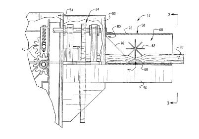
The safety output chute 12, with additional lel~lence to Figures 2 and 3, is
defined by housing 58, generally le~L~ lar in cross-section, open to receive a pad
as it passes through the cutting assembly 24 and ext-ontling away from the cutting
assembly in a d~w~lsLlcalll direction. The housing 58 is conl~ to the cutting
assembly enclosure 52 and is supported by the frame extension 56. Disposed within
the housing 58 is a rotatable, multivaned assembly 60 formed of a ~-lmlbel of vanes
or blades 62 extending radially from a shaft 64 which traverses laterally the
rectangular chute defined within the housing 58. The shaft 64 is rotatably mounted
to opposed sidewalls 66 of the housing 58 and is spaced from the bottom wall 68 in
order to accommodate a pad 70 in a somewhat con~ ,.,sed condition between the
vane 62 and bottom wall 68.
The vane 62 may be discollLilluous axially along ~e shaft 64 in the form of
discreet, spaced vane portion 72, as shown in Figures 1 and 3, or as axially
continuous vanes 74, as is shown in Figure 4. Also disposed within the housing 58
between the cutting assembly enclosure 52 and the vane assembly 60 is a deflector
panel 76 extPn(lin~ from the upper, ll~sLl~alll portion of the housing dowl~wal.lly
and dowl~Ll~ to the space 77 (Figure 4) bclween the vane assembly 60 and the
bottom wall 68 to direct a pad b~Lw~ell the bottom wall and the vane assembly. The
deflector panel 76 is preferably mounted at its upper distal end to ~e top wall 78 by
.. . . ... ..... . .. ..... .
CA 022~9266 1998-12-23
W O 98100288 PCTAUS97/11515
a hinge 80 and biased dow-~w~rdly. In operation, a pad 70 e~llelgillg through the
cutting assembly 24 and progressing through the safety output chute 12 will be
directed under the vane assembly 62 by the deflector panel 76, with the e.,.~ g
pad thus turning the vane assembly as the pad is forced through the safety output
chute. Concequ~Pntly, the pad 70 can be directed through the safety output chute 12
to an op~,.aLor while pre~e.,lillg the ingress of a hand past the vane assembly 62.
The pad is preferably colnplcssed by the vane assembly 60 to a thicknP5s such that
access is limited toward the cutting assembly 24, yet which still allows the pad to
resiliently expand to s~lbst~nti~lly its original unco~llplessed size. The space 77
between the vane assembly 60 and the bottom wall 68 and the ~lict~nre from the
space to the cutting assembly 24 is preferably correlated such that access to the
cutting assembly is limited by the combined effects of the narrow space 77 and its
~lict~nce to the cutting assembly located upstream thereof.
In some embo~;~"~ , the shaft 64 may extend through an end wall 66 of
the housing 58 for conn~ction to a knob 82, as is shown in Figure 4, to permit the
manual rotation of the vane assembly. This permits an operator to urge a pad 70
through the safety output chute 12 by rotation of the knob 82. This is particularly
advantageous where short sectionc of pad 70 are cut which may not extend throughthe output chute 12 through norrnal operation of the m~hinP.
The rotation of the vane assembly 62 may also be powered, such as is shown
in Figure 5, by extending the shaft 64 through the end wall 66 for coMection to a
sprocket 84. The sprocket 84 is powered by a coMection to the feed assembly 38
through the chain 86. The chain 86 is enmPchP(l with sprocket 84 of the safety
output chute 12 and sprocket 88 conn~cted to the shaft 90 which drives the gears 40
of the feed assembly 38. ConcequPntly, when the conversion assembly 22 (Figure
1) is producing a pad, as caused by the rotation of the gears 40, the vane assembly
62 will also be rotating to urge the forrned pad 70 (Figure 2) through the safety
output chute 12 to the operator.
A safety output chute 100 employing a sensor for sensing the presence of a
foreign object, such as the hand of an operator, etc., is illustrated in Figures 6 and
7 in colljullcLion with an exemplary cushioning conversion m~rhinP 10. The output
CA 022~9266 1998-12-23
WO 98/00288 PCTAUS97/11515
chute 100 includes a housing generally rect~n~ r in cross-section which is
connPcted to the cutting assembly enclosure 52 and supported by the frame
extension 56. The housing 102 defines a chute through which the pad formed by
the cushioning conversion assembly 22 travels to an opeldlor through an opening
104. Positioned near the opening 104 of the housing 102, on a side wall thereof, is
a sensor 106 for sensing the l,lesellce of an object within the chute defined by the
housing. The sensor 106 preferably has sensing access within the housing 102
through a port or access opening 108. The sensor 106 may be any one of a llul~lbe
of conventional sensors for sensing the ~i~,sence of a foreign object, such as an
infrared heat sensor or a c~p~rit~nre sensor, and gel~laling a signal responsive to
the absence or plesellce of such a foreign object, such as a human appendage, for
example a hand or fingers, in the housing 102 near the sensor. Preferably the
sensor 106 is capable of disc~ ting belween a pad and a foreign object such as
the hand of the operator. An infrared sensor, for example, could disc~ ate basedon the heat as a hand or fingers would give off more heat than a pad. A capacitance
sensor would discli~ based on the capacitance in the chute as the c~p~ci~nre
of a hand or fingers, for example, is different and distinguishable from the
capacitance of a pad.
The signal generated by the sensor 106 is provided through conventional
means to the process controller which is programrned to prevent the operation of the
cutting assembly 24, such as through disabling motor 46 of the cutting assembly 24,
when an object is in the hollsing 102 as sensed by the sensor 106. Allelnalively,
the signal geneldl~d by the sensor 106 can be routed to a circuit ~le~irated to
enabling or disabling the motor 46 powering the cutting assembly 24.
A labyrinth-like safety output chute 120is shown in Figures 8 through 10 in
conjunction with an e~.ompl~ry cushioning conversion m~r1linr 122. The
cushioning conversion m~r.~line 122 is similar in design to that described above- relative to Figure 1, and is more comprehensively described in U.S. Patent No.
5,322,477, for in.~t~nre, which is incorporated herein in its entirety by this
l~ ellce. (Reference numerals for assemblies of the cushioning conversion
m~cllinP 122 which perform the same general functions as assemblies of the
CA 022~9266 1998-12-23
wo 98/00288 PCT/US97/ll5l5
c~lchioning conversion m~hine 10 are decigl.~t~d by the same primed numbers.) Itshould be understood that the labyrinth output chute 120 may be equally employedwith a cushioning conversion m~hin~ of the type depicted in Figure 1 or a
cushioning m~rllin~ of a different type and that the safety output chutes 12 and 100
could be employed with the exemplary cushioning conversion m~r~in~ 122 of
Figure 8 or other cushioning conversion m~chin~s not illustrated or ~i.cc lsse
herem.
The labyrinth safety output chute 120 acts to prevent the ingress of the hand
of an ol,elalo~ to the blade 44' of the cutting assembly 24' by requiring the pad to
progress through the chute along a path, such as a generally tortuous, non-linear or
n~ ting path, that the hand and arm of an operator could not traverse. The
labyrinth output chute 120 includes a housing 124 mounted to an enclosure 52'
~ub~ lly enclosing cutting operation of the cutting assembly 24', the housing
defining a chute for a pad to travel though from the cutting assembly to the point of
an operator or other transitional or pad storage area. The housing 124 may be of a
constant cross-section or the housing may diverge in the dow,~L~cdlll direction as
shown in Figure 9. Disposed within the housing 124 are a number of cylindrical
guide rollers 126, 128 and 130 defining a tortuous path through the chute for the
pad to travel. Each guide roller 126, 128 and 130 includes a shaft 132 extendingbetween and rotatably mounted to opposite side walls 134 of the housing 124 suchthat the axis of rotation of the rollers will preferably be parallel to a plane which
passes laterally through the pad as it approaches the rollers from the cutting
assembly 24'. While not so limhed, the guide rollers 126, 128 and 130 are
preferably of the same length and extend subst~nti~lly across the lateral width of the
housing 124 bel~,e,l side walls 134. Preferably the open space between the outerperipheries of adjacent guide rollers 126, 128 and 130 is deLellnilled so as to permit
a pad to fit therebelweell with minim~l con~lession of the pad. Further, the
vertical (1i~t~n~e between the centerlines of the guide rollers is so chosen that the
pad is forced to follow an un~ ting or solllewllat inclined "S" shape path and to
bend or Imrl~ te in a subst~nti~lly vertical direction to follow the path. Although
the guide rollers 126, 128 and 130 are shown as being spaced s~bst~nti~lly the same
CA 022~9266 1998-12-23
W 0 98100288 PCT~US97/11515
di.~ re from each other, the guide rollers can be offset so that the ~ re b~weena~jaçent rollers is not the same.
Instead of the guide rollers 126, 128 and 130 being att~ch~d in fLxed
positions within the housing 124 the shafts 132 alle~ ively could be independently
spring biased with the travel for each roller being limited such that the rollers
continue to overlap so as to m~int~in a labyrinth function. The housing 124 could
also be provided with lateral guides in order to direct the travel of the pad between
the rollers 126, 128 and 130.
The rotation of the guide rollers 126, 128 and 130 could be effected
passively, by movement of the pad through the labyrinth, or actively, either by a
s~a.~te motor 136 driving one or more of the guide rollers, or by coupling one or
more of the guide rollers to the feed assembly 38' much in the same way as the
vane assembly 62 is coupled to the feed assembly 38 in the manner shown in Figure
5.
The outer surface of each guide roller 126, 128 and 130 preferably allows
sliding contact with the pad in an application where the rollers are not poweredsepal~t~ from the movement of a pad therebetween, and a so-llewl.at glippillg
contact with the pad when the rollers are separately powered to urge the pad
through the labyrinth output chute 120. The construction of the rollers 126, 128and 130 may be chosen a variety of materials based on the application.
Additionally, if desired, the rollers could serve a dual purpose by also pe.roldting
the pad or making a ",~-ki~.g on the pad so as to facilitate use of a pad lengthmeasuring device in conjunction with the labyrinth safety output chute 120.
In operation, a pad (not shown) formed by the conversion assembly 22'
passes through the cutting assembly 24' to the labyrinth safety output chute 120where its is fed above the first guide roller 126 rolalillg clockwise, below thesecond guide roller 128 rotating counterclockwise and above the last guide roller
130 rotating clockwise and then e~ n~tes from the chute for use by the operator.A further embodiment of an safety output chute 150 for use with a
cushioning conversion m~rhinP, such as the m~hinP 10 illustrated in Figure 1, isshown in Figures 11 and 12. The safety output chute 150 includes a housing 152 of
CA 022~9266 1998-12-23
W O 98/00288 PCTrUS97111'.15
14
the same basic design as the housing 102 shown in Figures 6 and 7 and described
above. Disposed within the chute defined within the housing 152 is a shield 154
which is conn~cte~ at its u~Lrealn end 156 to the upper, u~sLl.,alll portion of the
housing by a hinge 157. The shield 154 extends dOwllwaldly in the dowl~Ll~alll
direction to define a space lS8 be~w~ell the distal end 160 of the shield 154 and the
bottom wall 162 of the housing 152 through which the pad 70 traverses. Extendingfrom the shield 154 through a side wall 164 of the housing 152 in order to be
operative outside of the housing 152 is a lever 166 which moves with shield 154
within the housing. The lever 166 is conn~cted to a piston portion 168 of a
solenoid 170 which is in turn mounted to the outer face of the side wall 164 of the
housing 152. Operation of the solenoid 170 thus moves the lever 166 and likewisethe shield 154 within the housing 152. A limit switch 172 mounted to the outer
face of the side wall 164 of the housing 152 below the lever 166 genelaL~s a signal
indicative of whether the lever, and thus the shield 154, are in their lowermost or
lS closed condition, whe~ill the shield slightly co~ sses the pad 70 or senses the
presence of a hand in the chute because the chute is in a relatively raised position.
The solenoid 170 is controlled by the previously noted process controller 51 which
also receives the signals generated by the limit switch 172. Preferably the lever
166, the solenoid 170 and the limit switch 172 are contained within an enclosure174.
In operation, while a pad 70 is being formed by the conversion assembly 22,
the piston portion 168 of the solenoid 170 is in a retracted state thus drawing the
lever 166 and shield 154 to a relatively upper or open state away from the bottom
wall 162 thus increasing the space 158 through which the pad may traverse withinthe chute. Upon initiation of a cutting operation, the process controller S l causes
the solenoid 170 to extend the piston portion 168 forcing the lever 166 and the
shield 154 relatively dowllwaldly to narrow the space 158 and co~ ess the pad 70therein. The force exerted by shield 154 on the pad is preferably adequate to
compress the pad as desired, but limited so as not to present a hazard to a handbelow the shield. If only the pad is in the chute, then this action causes the lever
166 to contact the limit switch 172 which generates a signal to the process
CA 022~9266 1998-12-23
WO 98/00288 PCT/US97/11515
controller 51 ;..~ic~ g that the shield 154 is in its relatively closed position. Upon
receipt of the signal from the limit switch 172 co~ ,lhlg that the shield 154 is in
its closed position, the process controller 51 causes the cutting assembly 24 toexecute a cut of the pad 70. If a foreign object were in the opening 158 p~cvellling
the shield 154 from re~hing its fully closed position, the process controller 51,
sensing this fact from the output of the contact switch 172 in its open position,
would prevent the e~rPcl3tion of a cut. Furthermore, if the shield 154 were forced
open, away from its closed position, during a cutting operation, the process
controller 51 would h~ t the cutting operation. Alternatively of the limit switch
172 providing a signal to the process controller S1, the limit switch may act as a
true switch in series with the cut motor or solenoid 46 preventing its operationwhen the limit switch is in its open position.
With lcfelclue to Figures 13 through 16 there is shown an embodiment of a
safety output chute 200 for collecting cut pads once they have been cut and
deposited into the chute. The safety output chute 200 is connPctecl to a cushioning
conversion m~rhinP 10 dowl~L~ of the cutting assembly (not shown) adjacent an
output passage 202 (Figure 15). In this embodiment the safety output chute 200 and
cushioning conversion m~rhinP 10 function cooperatively in a manner similar to avending m~rhin~. The safety output chute 200 includes a cover 204 mounted to a
chute body 206 by means of a hinge 208. Preferably the cover 204 includes a
llalls~a.c"t insert 210 which permits the ~ lo~ to see a pad within the safety
output chute 200. It is also preferable that during the formation of a pad and while
the pad is being cut to the desired length, the cover 204 be locked into a closed
position and that only upon the completion of a cutting operation is the operator
pc, l~ r~l to open the cover to obtain the pad from inside the chute. The safetyoutput chute 200 may also, but not l-ecess~,ily, include an assembly 212 which
permits a pad to travel from the m~r~inP to the safety output chute 200 when thecover 204 is in its closed position, as shown in Figure 15, but which closes offaccess to the m~chinP and cutting assembly (not shown) through the opening 202
when the cover is in an open position, as shown in Figure 16. The closure
assembly 212 includes a sliding door element 214 which is operable to slide
CA 022~9266 1998-12-23
W O 98/00288 PCT~US97/11515
16
vertically within guides 216 spaced at opposite lateral sides of the chute 200. The
sliding door 214 includes a vertical projection 218 including a wheel 220 at an end
distal from the main portion of the door for contact with the inside surface 222 of
the cover 204. The sliding door 214 is biased vertically upwardly by a pair of
springs 224. Consequently, when the cover 204 of the safety output chute 200 is in
a closed position, as shown in Figure 15, the wheel 220 is forced dowllwaldly
causing the sliding door to slide dowllw~ldly by co~ )ressillg the springs 224 and
pel~lliL~ access via the opening 202 to the cutting assembly for receipt of a pad.
When the door 204 is in an open position, the springs 224 urge the sliding door 214
in an upward direction to s~bst~nti~lly cover the passage or opening 202 and permit
access to the cutting assembly. When the cover 204 is again closed it will contact
the wheel 220 which will rotate against the underside 222 of the cover 204 as the
cover forces the sliding door 214 downwardly by colll~lessing the springs 224 and
again p~ g access be~ween the m~t~,hin~, and the safety output chute 200 via thelS passage 202. The safety output chute 200 may be provided with sensors or limit
switches (not shown) to sense whether the cover 204 is in an open or closed
position and to disable or enable a cutting operation accordingly.
The end of the safety output chute 200 remote from the m~chin~ 10 can be
open or closed. An open end permits pads of llnlimite~l lengths to be produced, but
in such an in~t~nre the chute should be of sufficient length to inhibit physical access
by the ~elator to the cutting assembly 24 from the open end.
A further embodiment of a safety output chute 230 configured with a
cushioning conversion m~rhin~ 10 to operate analogous to a vending machine is
shown in Figures 17 through 20. In this embodiment, the m~r.hinP, 232 is
preferably supported on a frame 234 in an upright, vertical position. In such anin~t~nre the frame may also include casters 236 to facilitate movement of the
cushioning conversion m~r,hin~, to an applop.ia~e location where strip material is
desired at a given time. The cushioning conversion m:lrhinP, 232 is preferably
oriented vertically with the stock supply assembly 18 located relatively near the
floor and the m~r.hin~ output 238 facing upwardly. The safety output chute 230 is
mounted in a vertical orientation adjacent the cushioning conversion m~rhinP 232
CA 022~9266 1998-12-23
WO 98/00288 PCTIUS97/11515
by a llul~ber of mounting brackets 240. A pad is transferred from the cushioningconversion m~rhinr 232 to the safety output chute 230 through a 180~ arcuate
passage 242 located above the cushioning conversion ".~r.hi..e and the output chute.
The safety output chute 230 preferably includes a cover 244 mounted to the chutebody 246 by a hinge 248. The chute cover 244 preferably also inrll~cles a
,alelll window insert 250 to permit the ope~dtor to visually d~lmine whether
a pad has been deposited into the safety output chute 230. The safety output chute
230 is provided with a sensor or limit switch which permits operation of the
cushioning conversion m~hin~ 232 only when the door 244 is shut and may either
alternatively or with the limit switch include a means for locking the cover 244 in a
closed con~liti~ n when the cushioning conversion m~rhin~ is in operation. The end
of the output chute 230 remote from the cushioning conversion m~rhin~ 232 may beopen or closed. However, when the end of the output chute 230 is open, as
tliccl~ssed above, the length of the chute should be sufficiently long to inhibit
physical access by the operator to the cutting assembly 24 from the open end of the
chute.
A m~rhin~ output closure assembly 252 may also be provided to close the
m~rhine outlet 202 when the cover 244 is in an open position, as shown in
Figure 20 and to open access from the m~r.hinP. output to the arcuate passage 242
when the cover is closed, as shown in Figure 19. The closure mPch~nicm 252 is
configured similar to the closure mPcl-~ni!i", 212 illustrated in Figures 15 and 16.
The closure mrc.h~ni.cm 252 includes a sliding door 254 which ~lle, ~ ely opens
the m~r.hinr outlet 202 when in a retracted position and closes access to the m~r.hine
output when in its ulllelldcted position when the door 244 of the safety m~rhin~output chute 230 is open. The sliding door 254 slides holi~onlally within the slides
256 and is biased towards a closed position by springs 258. An extension 260
e~t~ling from the sliding door 254 and It~ g in a wheel 262 engages the
cover 244 to urge the sliding door into an open or closed position depending upon
the position of the cover 244. Consequently, when the door 244 is in a closed
position, as shown in Figure 19, the sliding door 254 is urged towards its open
condition retracting the springs 258 to permit access through the m~rhin~ outlet
CA 022~9266 1998-12-23
W 098/00288 PCTrUS97/11515
18
202. Conversely, when the cover 244 is in an open condition the springs 258 urgethe sliding door 254 into a closed position covering the m~rllinP output 202, thus
precl~ ing access to the ",~rl~in~ and the cutting assembly.
A partially retractable safety output chute 300 is illustrated in Figures 21
S through 25. As seen in the cross-sections of Figure 21 and 22, the chute 300 is
formed by co~ onlillg lower and inverted upper tray shape elemrnt.c 302 and 304.The lower tray 302 is rigidly conn~ctecl to the cutting assembly enclosure 52 at an
end 306 while the upper tray 304 is hingedly connrctecl to the cutting assembly
enclosure by the hinge 308 to pivot upwardly away from the lower tray and provide
access to within the output chute 300. The lower and upper trays 302, 304
cooperatively diverge away from the cutting assembly enclosure 52 to form the
chute output 310. A deflector plate 312 guides a formed pad 314 (Figure 24) fromthe cutting assembly enclosure 52 through the output chute 300.
Disposed within the output chute 300 hingedly connrcted to the upper tray
304, near the upper wall 315, is a chute guard 316. The chute guard 316
preferably extends from the upper tray 304 sufficiently that when the chute 300 is
closed and a pad is not present in the chute, the distal end of the chute guard
contacts the lower tray 302 and cannot be freely deflected toward the cutting
assembly. The chute guard 316 is preferably composed of two offset curtains or
rows 318, 320 of several independent flaps 322, 324, respectively, each rotatably
corlnected to a rod 326 e~temling between side walls 328 of the upper tray 304 to
effect the hinged connection between the upper tray 304 and the chute guard. Theflaps 322 of row 318 are offset with the flaps 324 of row 320 by a (li.ct~nre of one-
half of the axial length of a flap so that ingress from the chute opening 310 to the
cutting assembly enclosure 52 requires that at least one flap of each row be
oulwaldly displaced.
A secondary chute guard 330, is hingedly conn~cted to the lower tray 302
and biased, such as through spring 332, away from the bottom wall 334 of the
lower tray to protrude into chute area. The secondary chute guard 330 is angled in
its extended biased condition toward the chute opening 310 so that the secondarychute guard can be pressed toward the bottom wall 334 of the lower tray to
CA 022~9266 1998-12-23
W 098/00288 PCT~US97111515
accornmodate a pad through the chute as shown in Figure 24. The secondal y chuteguard 330 cooperates with the chute guard 316 to further inhibit access to the
cutting assembly enclosure 52 from the chute output 310.
When a pad is not present in the output chute 300 as is the condition shown
in Figure 21, the chute guard 316 extends dow~lw~ldly away from the upper tray
304, such as through the force of gravity, preferably to contact the bottom wall 334
of the lower tray 302. The secondary chute guard 330 is biased away from the
bottom wall 334 of the lower tray 302 to protrude into confines of the output chute.
The chute guard 316 and secondary chute guard 330 thus require for an object to
progress from the chute output 310 to the cutting assembly enclosure 52 that theobject pass below the chute guard 316 and above the secondary chute guard 330 toeffectively inhibit access to the cutting assembly 24 within the cutting assembly
enclosure 52.
When a pad 314 has been formed by the conversion assembly 22 (Figure 1)
and has been fed through the cutting assembly 24 (Figure 1) and the safety output
chute 300, as shown in Figure 24, the pad will depress the secondary chute guard330 dowllwardly toward the bottom wall 334 and will deflect the chute guard 316
ouLw~dly and upwardly toward the top wall 315 of the upper tray 304. While the
chute guard 316 and secondary chute guard 330 are in their lespe,;Live relatively
retracted conditions, ingress through the chute from the chute output is inhibited by
the pl~sellce of the pad 314 in the output chute along with the chute guards.
The upper tray 304 my be retracted by lifting the output end of the upper
tray around the hinge 308, as shown in Figure 25, to provide access within the
interior of the output chute 300. When the upper tray 304 is lifted upwardly, the
chute guard 316, through the force of gravity, will rotate downwardly away from
the upper wall 315 of the upper tray 304 to protrude substantially across the
opening 340 between the cutting assembly enclosure 52 and the output chute 300 to
at least partially restrict, with the secondary chute guard 330, access to the cutting
assembly 24.
The lower and upper trays 302 and 304 are preferably provided with a keyed
safety interlock switch embodied through the key 342 protruding from the upper
CA 022~9266 1998-12-23
W O 98/00288 rcTrusg7/11515
tray for capture by a receptacle element 344 in the lower tray. The keyed interlock
switch provides an in(lir~tion to the cushioning conversion m~rllin~ of whether the
output chute is open or closed to be used in a logic circuit or by the m~rllinr
controller S1 (Figure 1) to prevent engagement of the cutting assembly 24 when the
upper tray is not in a closed position.
Turning to Figures 26 and 27, there is shown a powered chute guard
assembly 350. The powered chute guard assembly includes a chute guard or shield
352 disposed within a divelgellt output chute 354 and an ~ct~ting m~cll~ni~m 356,
such as a linear motor or a ~ u ~l~tir, hydraulic or electric solenoid powering a rod
358 in engagement with the chute guard 352 through a rotatable connection 359.
The chute guard 352 is hingedly co----~;lr~l at its interior end, through a hinge 360,
to the defl~ctor plate 312 secured to the cutting assembly enclosure 52 to allow it to
move between an open position shown in Figure 26 and a closed position shown in
Figure 27. In the open position, the pad 361 may progress through the output chute
354 relatively nnhin-lered by the chute guard 352, such as when the pad 361 is
being produced. In the closed position, the chute guard 352 co~ sses the pad
361 somewhat to prevent ingress of an object through the output chute 354 from the
output end 362, such as when a pad is being severed by the cutting assembly 24.
The solenoid 356 is mounted to a mounted plate 364 spaced from the cutting
assembly enclosure 52 by spacers 366 so that the rod 358 exten(1ing from the
solenoid 356 connects to the chute guard 352 at a suitable ~i~t~nre from the hinge
360. A coiled col~ ession spring 368 coaxial with the rod 358 and extrn-ling
between a shoulder 370 of the rotatable connector 359 and the lower surface of aflange 372 biases the rod 358 and chute guard 352 downwardly to a closed position,
as shown in Figure 27. .Altern~tively, the spring 368 could be located elsewhere to
perform the same function, such as embodied into the solenoid 356. The force of
the spring 368 is preferably sufficient to compress the pad 361 to a thickness that
would be less than that of a hand, while not ~m~ging the pad, for example
approximately 3/4 of an inch. The spring force should also not be so strong as to
cause harm to a person's hand or fingers if they were to be beneath the chute guard
CA 022~9266 1998-12-23
WO 98/00288 PCT/US97/11515
352 upon being moved t~alds its closed position. Preferably the cutting assemblycan execute a cutting cycle only when the chute guard 352 is in this closed position.
The position of the chute guard 352 is ~etec~P~ by a contact sensor 374
mounted to the flange 372 and having a contact 376 for contact with a finger 378secured to the rod 358 to move axially with the rod. The sensor 374 ge~ es a
signal indicative of whether or not the contact is deplessed by the finger 378 which
is provided to a logic circuit or the m~r.hinP. controller Sl of the cushioning
collvélsion m~rhinP for use in d~le. ~l~inil~g whélll~ . the m~rhinP may sever the pad
361 in the output chute.
While a pad is being produced the solenoid is ellelgi;c~d, causing the rod 358
to retract, co,l~plessillg the spring 368 and pulling the chute guard 352 upwardly
into the open position, shown in Figure 26, to allow the pad 361 to progress
through the chute 354 as it is being formed. Once the pad has been formed to thedesired length and a cutting operation is to be initi~tPd, the solenoid is de-ene.~i~.ed
and the force of the spring 368 causes the rod 358 and ~tt~chPd chute guard 352 to
move dowllwal-lly into the output chute, as shown in Figure 27. With the chute
guard fully lowered and the pad colllp,essed, the finger 378 will depress the contact
376 and the sensor 374 will generate a signal to the cushioning conversion m~rhinP
allowing a cut operation to take place.
If an obstruction has prevented the chute guard 352 from lowering fully, the
flnger 378 will fail to depress adequately the contact 376 and as the sensor 374 will
not genel~t~ the chute closed signal, thus preventing a cutting operation from being
~e~ecuted.
.. n-l ively to the coiled colllplession spring 368 biasing the rod 358 and
chute guard 352 to its closed position, a coiled extension spring can be secured to
the flange 372 and shoulder 370 and can bias the chute guard 352 in its open
position. In this case, the solenoid 356 would not be ene,~,i~d during a pad
forming and feeding operation, but would be e~ ized to overcome the spring bias
and cause the rod 358 to extend downwardly on being eneL~ ed. To p~lrOll,l a
cutting operation, the solenoid 356 is enelgi;ced and, if the chute guard 352 can be
CA 022~9266 1998-12-23
WO 98/00288 PCT/US97/11515
deplessed s~rr~r;e~ y to reach its closed position, the sensor 374 will sense the
finger 378 deprcssil g the contact 376 and the cuKing operation will be p~
Further, the solenoid 356 and rod 358 could be oriented hol~onlally, with
the hol~o~ l motion of the rod tr~n~l~ted into hinged movement of the chute guard
352 through conventional mP.thorl~.
In some applications, it may be useful to conlou~ and extend an output chute
guard 380 as shown in Figure 28 so that a relatively smaller area of the chute guard
depresses a smaller area of the pad 361 (Figure 27), preferably outside of the output
chute 354', to reduce the amount of force n~cess~. y to COl~ .,SS the pad sufficiently
to prevent ingress of a foreign object into the chute during cutting operation. The
design of the output chute 354', the solenoid 356', rod 358' and sensor may be the
same or similar to the like llulllbf~,d components described above relative to
Figures 26 and 27. With the distal portion of the chute guard 380 positioned
outside of the output chute 354', the pad is caused to curve dow,lv~ldly about the
lower distal edge 381 of the output chute when the chute guard is in its lowered or
closed position 380a, subst~nti~lly ple~ g ingress into the chute from below thepad. A output chute deflector 382 positioned over the output 384 of the output
chute inhibits ingress into the chute above the pad. Control and actuation of the
chute guard 380 between its closed 380a and open 380b positions can be
accomplished similarly to that described imm~ tely above relative to Figures 26
and 27~ with the actuator ".f~h~ni~m and spring being adapted as discussed above to
provide a biased closed or biased open operation.
In Figure 29, there is shown an embodiment of an output chute 354" with a
chute guard 380" similar to that shown in Figure 28, with the exception that thechute guard 380" is adapted to contact the pad 361 within the output chute.
Preferably the output chute guard 380" contacts the pad within the output chute
354" over a small area of contact such as along a line transverse to the direction to
the movement of the pad through the output chute to reduce the amount of force
required to collll)less the pad. The chute guard 380" may thus be in the form of a
generally flat plate which extends dow-lwar lly abruptly near its distal end 390 to
contact the pad 361. The chute guard 380" may operate between an open position
CA 02259266 1998-12-23
WO ~a!0~8 P~T~S9-/11;15
23
,gO"~ and ~ elo~ed posi~ion 3~0"~ s~n~ilar to the chu~e ~ d ~ dlsc.lssed a~ov~.
Althollgll i~e ~Yentio~ has be~n shovvn an~ cles&ril~ed ~ith res?ect t~ ~erta~n
eIe.~e~t embo~-.~ents, it is obvious that equivalent ~ke~ations arld mc ~ific;3~ions
occur ~o oth~rs s~led ~n the art upon the re~ding ~n~ e~n~l;n~ of ~.ls
specilication. The present in~ention ~ncludes all s~lch equivalent dLter~r.ons and
n~odific~tions, ~d is l~mited cnly b~ the scope of tue foilo~ny claims. Fur~er~r~ore
the cor~espondi~g stmcru~es, materizls, ~cts, ~d e~lUlv~lle~t3 OI 3!! means or s~ep ~
A~nc~;on eleme-~ts ~t rhe cl~im~ beiow ~re int~nfied to include ~y s~rare, m~ter.al.
or acts f~r performing the lunction3 i~ combi~auon u~llh the othc:r ~ od 51e~e.'1l:5 as
1 G specific~lly ciaiIrect.
, .