Note: Descriptions are shown in the official language in which they were submitted.
CA 022~9272 1998-12-24
W O g7/49340 -1- PCT~US97/10158
MULTI-~u~ ONAL SURGICAL CONTROL SYSTEM
AND SWITCHING lNl~FACE
BACKGROUND OF THE lNVl!il!~L lON
1. FIELD OF THE lNV~ lON
The present invention generally relates to
control systems. More particularly, the present
invention relates to an interface that allows
multiple surgical devices to be controlled from an
input device, such as a foot pedal.
2. DESCRIPTION OF REhATED ART
Many surgical procedures are performed with
multiple instruments. For example, some
laparoscopic procedures are performed utilizing a
robotic arm system produced by Computer Motion,
Inc. of Goleta, California to hold and move an
endoscope. The surgeon may also use a laser to
cut tissue and an electrocautery device to
- cauterize the tissue. Each instrument has a
unique control panel or foot pedal to operate the
device. The surgeon must therefore depress one
foot pedal to move the robotic arm and endoscope,
depress a different foot pedal to actuate the
electrocautery device, and manipulate yet another
input device to energize the laser. Operating
multiple input devices may distract the surgeon,
thereby reducing the efficiency and safety of
performing the procedure. It would therefore be
desirable to provide an interface that would allow
the surgeon to select and control multiple
surgical devices from a single input device.
CA 022~9272 1998-12-24
W097/49340 -2- PCT~Sg7/10158
Additionally, it is also desirable to provide an
interface that would allow the surgeon to mutually
exclusively select and control multiple surgical
devices from an input device.
SUMMARY OF THE lNv~:NlION
The present invention provides an interface
for coupling an input device to a first surgical
apparatus and a second surgical apparatus, the
interface comprising:
(a) a first input channel coupled to the input
devlce;
(b) a first output channel coupled to the
first surgical apparatus;
(c) a second output channel coupled to the
second surgical apparatus;
(d) a select channel configured to switch said
first input channel between said first output
channel and said second output channel.
The interface allows a surgeon to operate
multiple surgical devices from a single input
device. The input device may be a foot pedal that
provides output signals to actuate a number of
different surgical devices. The surgical devices
may include a robotic arm system, a laser, an
electrocautery device, or an operating table. The
interface has an input channel that is coupled to
the input device and a plurality of output
channels that are coupled to the surgical devices.
The interface also has a select channel which can
receive input commands and correspondingly switch
the input channel between one of the output
channels. The select channel may be coupled to a
speech interface that allows the surgeon to select
one of the surgical devices with a voice command.
The surgeon can then operate a specific device
CA 022~9272 1998-12-24
W O 97/49340 -3- PCT~US97/10158
after providing an input or switching command
which switches the input channel to the desired
output channel and thereby connects the input
device with the desired surgical device.
BRIEF DESCRIPTION OF THE DRAWINGS
The objects and advantages of the present
invention will be readily apparent to those
ordinarily skilled in the art after reviewing the
following detailed description and accompanying
drawings, wherein:
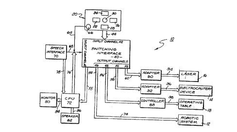
Figure 1 is a schematic of a control system
and interface in accordance with the present
invention.
DETAILED DESCRIPTION OF THE INVENTION
Referring to drawings more particularly by
reference numbers, Figure 1 shows a surgical
system 10 in accordance with the present
invention. The system 10 allows a surgeon to
operate a number of different surgical devices 12,
14, 16 and 18 from a single input device 20.
Providing a single input device reduces the
complexity of operating the various devices and
improves the efficiency of a surgical procedure
performed by a surgeon.
Surgical device 12 may be a robotic arm which
can hold and move a surgical instrument. The arm
12 may be a device such as that sold by Computer
Motion, Inc. of Goleta, California under the
trademark AESOP. The arm 12 is commonly used to
hold and move an endoscope within a patient. The
system of the present invention allows the surgeon
,
CA 022~9272 1998-12-24
W097/4g340 -4- pcT~ss7tlols8
to control the operation of the robotic arm 12
through the input device 20.
Surgical device 14 may be an electrocautery
device. Electrocautery devices typically have a
bi-polar tip which carries a current that heats
and denatures tissue. The device is typically
coupled to an on-off switch to actuate the device
and heat the tissue. The electrocautery device
may also receive control signals to vary its power
output. The system 10 of the present invention
allows the surgeon to control the operation of the
electrocautery device through the input device 20.
Surgical device 16 may be a laser. The laser
16 may be actuated through an on-off switch.
Additionally, the power of the laser 16 may be
controlled by control signals. The system 10 of
the present invention allows the surgeon to
control the operation of the laser 16 through the
input device 20.
Device 18 may be an operating table. The
operating table 18 may contain motors and
mechanisms which adjust the position of the table.
The present invention allows the surgeon to
control the position of the table 18 through the
input device 20. Although four surgical devices
12, 14, 16 and 18 are described, it is to be
understood that other functions within the
operating room may be controlled through the input
device 20. By way of example, the system 10 may
allow the surgeon to control the lighting and
temperature of the operating room through the
input device 20.
The input device 20 may be a foot pedal which
has a plurality of buttons 22, 24, 26, 28 and 30
that can be depressed by the surgeon. Each button
is typically associated with a specific control
CA 022~9272 1998-12-24
W O 97/49340 -5- PCT~US97/10158
command of a surgical device. For example, when
the input device 20 is controlling the robotic arm
12, depressing button 22 may move the arm in one
direction and depressing button 26 may move the
arm in an opposite direction. Likewise, when the
electrocautery device 14 or laser 16 are coupled
to the input device 20, depressing button 30 may
energize the devices, and so forth and so on.
Although a foot pedal is shown and described, it
is to be understood that the input device 20 may
be a hand controller, a speech interface which
accepts voice commands from the surgeon, a
cantilever pedal or other input devices which may
be well known in the art of surgical device
control.
The system 10 has a switching interface 40
which couples the input device 20 to the surgical
devices 12, 14, 16 and 18. The interface 40 has
an input channel 42 which is connected to the
input device 20 by bus 44. The interface 40 also
has a plurality of output channels 46, 48, 50 and
52 that are coupled to the surgical devices by
busses 54, 56, 58, 60, 94, 96, 98 and which may
have adapters or controllers disposed in
electrical communication therewith and
therebetween. Such adapters and controllers will
be discussed in more detail hereinbelow.
Because each device 12, 14, 16, 18 may require
specifically configured control signals for proper
operation, adapters 90, 92 or a controller 88 may
be placed intermediate and in electrical
communication with a specific output channel and a
specific surgical device. In the case of the
robotic arm system 12, no adapter is necessary and
as such, the robotic arm system 13 may be in
direct connection with a specific output channel.
CA 022~9272 1998-12-24
W097t49340 -6- PCT~S97/10158
The interface 40 couples the input channel 42 to
one of the output channels 46, 48, 50 and 52.
The interface 40 has a select channel 62 which
can switch the input channel 42 to a different
output channel 46, 48, 50 or 52 so that the input
device 20 can control any of the surgical devices.
The interface 40 may be a multiplexor circuit
constructed as an integrated circuit and placed on
an ASIC. Alternatively, the interface 40 may be a
plurality of solenoid actuated relays coupled to
the select channel by a logic circuit. The
interface 40 switches to a specific output channel
in response to an input signal or switching signal
on the select channel 62.
As depicted in Fig. l, there may be several
inputs to the select channel 62. Such inputs
originate from the foot pedal 20, the speech
interface 70 and the CPU 72. The interface 40 may
have a multiplexing unit such that only one
switching signal may be received at the select
channel 62 at any one time, thus ensuring no
substantial hardware conflicts. The
prioritization of the input devices may be
configured so the foot pedal has highest priority
followed by the voice interface and the CPU. This
is intended for example as the prioritization
scheme may be employed to ensure the most
efficient system. As such other prioritization
schemes may be employed. The select channel 62
may sequentially connect the input channel to one
of the output channels each time a switching
signal is provided to the select channel 62.
Alternatively, the select channel 62 may be
addressable so that the interface 40 connects the
input channel to a specific output channel when an
address is provided to the select channel 62.
,
CA 022~9272 1998-12-24
W O 97/49340 -7- PCTAJS97/10158
Such addressing is known in the art of electrical
switches.
The select channel 62 may be connected by line
64 to a dedicated button 66 on the foot pedal 20.
The surgeon can switch surgical devices by
depressing the button 66. Alternatively, the
select channel 62 may be coupled by line 68 to a
speech interface 70 which allows the surgeon to
switch surgical devices with voice commands.
The system 10 may have a central processing
unit (CPU) 72 which receives input signals from
the input device 20 through the interface 40 and
bus 55. The CPU 72 receives the input signals,
and can ensure that no improper commands are being
input at the controller. If this occurs, the CPU
72 may respond accordingly, either by sending a
different switching signal to select channel 62,
or by alerting the surgeon via a video monitor or
speaker.
The CPU 72 can also provide output commands
for the select channel 62 on bus 76 and receive
input commands from the speech interface 70 on the
same bi-directional bus 76. The CPU 72 may be
coupled to a monitor 80 and/or a speaker 82 by
buses 84 and 86, respectively. The monitor 80 may
provide a visual indication of which surgical
device is coupled to the input device 20. The
monitor may also provide a menu of commands which
can be selected by the surgeon either through the
speech interface 70 or button 66. Alternatively,
the surgeon could switch to a surgical device by
selecting a command through a graphic user
interface. The monitor 80 may also provide
information regarding improper control signals
sent to a specific surgical device 12, 14, 16, 18
and recognized by the CPU 72. Each device 12, 14,
CA 022~9272 1998-12-24
W O 97/49340 -8- rCTrUS97/10158
16, 18 has a specific appropriate operating range,
which is well known to the skilled artisan. As
such, the CPU 72 may be programmed to recognize
when the requested operation from the input device
20 is inappropriate and will then alert the
surgeon either visually via the monitor 80 or
audibly via the speaker 82. The speaker 82 may
also provide an audio indication of which surgical
device is coupled to the input device 20.
The system 10 may include a controller 88
which receives the input signals from the input
device 20 and provides corresponding output
signals to control the operating table 18.
Likewise, the system may have adapters 90 and 92
which provide an interface between the input
device 20 and the specific surgical instruments
connected to the system.
In operation, the interface 40 initially
couples the input device 20 to one of the surgical
devices. The surgeon can control a different
surgical device by generating an input command
that is provided to the select channel 62. The
input command switches the interface 40 so that
the input device 20 is coupled to a different
output channel and corresponding surgical device
or adapter. What is thus provided is an interface
40 that allows a surgeon to select, operate and
control a plurality of different surgical devices
through a common input device 20.
While certain exemplary embodiments have been
described and shown in the accompanying drawings,
it is to be understood that such embodiments are
merely illustrative of and not restrictive on the
broad invention, and that this invention not be
limited to the specific constructions and
arrangements shown and described, since various
CA 02259272 1998-12-24
W097/49340 -9- PCT~S97/10
other modifications may occur to those ordinarily
skilled in the art.