Note: Descriptions are shown in the official language in which they were submitted.
CA 022~9~21 1999-01-04
ELECTROMAGNETIC RADIATION TRANSMITTER/REFLECTOR
DEVICE, APPARATUS AND METHOD TEREFOR
The present invention relates to an ultraviolet electromagnetic radiation transmitter/
reflector device comprising a straight glass tube with an end-to-end bore for retaining
a pressurised ionising gas, extending therethrough around an axis and defining aradiation transmitter beam.
It also relates to apparatuses and a process implementing such a device.
The invention finds a particularly important, although non-exclusive, application in
the field of photochemical treatment of materials by ultraviolet radiation with
transmitter tubes containing an ionising gas at high or medium pressure, for example
used in the paper industry, textiles, plastics industry, food industry, automobile
industry and in the printing field, in particular for polymerization of inks or varnishes
on films, for example formed by rolls of paper c,r cardboard
By high or medium pressure we mean absolute gas pressures greater than or equal
to 2 kg/cm2, for example 3 kg/ cm2for a mediurn pressure and greater than 5 kg/ cm2
for a high pressure, being able for example to ~go up to 100 kg/ cm2.
The invention is not limited to the types of prociucts to be treated. It can for example
be used for drying of plated products, for drying of certain varnishes and adhesives,
for drying of wire products extending around an axis, or for sterilization of liquid
products.
Devices for production and ref!ection of ultraviolet radiations are already known
comprising a straight transmitter tube and a straight concave reflector having aparabolic cross section or an elliptic cross section.
These devices present drawbacks. They are in fact cumbersome and require a
transmitter tube completely separated from the reflector by a distance of several
millimetres to enable efficient cooling by air flow between the transmitter tube and
reflector.
High temperatures from 600 to 900~ are in fact observed on the ultraviolet
transmitter, whereas the temperature of the reflector is much lower, for exampleabout 50~C.
The materials used are moreover different, the transmitters being made of glass and
the reflectors of reflecting metal, of the aluminium type, i.e. presenting a very
different thermal expansion coefficient from that of glass.
CA 022~9~21 1999-01-04
The tubes of great length of the devices of the prior art moreover present buckling
with time.
In the case more particularly concerned by the invention, i.e. ultraviolet radiation
transmission, known transmitters also cause formation of ozone in non-negligiblequantity.
The object of the present invention is to provide a radiation transmitter/reflector
device, an apparatus and a process implementing such a device, meeting the
requirements of practice better than those known before, in particular in that it
proposes a compact device which is not cumbersome, able to considerably limit
ozone production while maximizing the usable photochemical energy due to a
structural design enabling an excellent optimization of the energy efficiency of the
transmitted radiation.
For this purpose, the invention proposes in particular an ultraviolet radiation
transmitter/reflector device comprising a straight glass tube with an end-to-end bore
for retaining an ionising gas under high or medium pressure, extending around anaxis, and defining a radiation transmitter beam, and a surface for reflecting the
transmitted radiation comprising two longitudinal side wings symmetrical in relation to
an axial plane of the bore, the reflecting surface being at least partially secured to
the transmitter tube and presenting a transverse cross section at least partially
parabolic, elliptic or straight, or then again at least partially appreciably parabolic,
appreciably elliptic or appreciably straight, characterized in that the portions of
reflecting surface corresponding to the side wings and presenting a transverse cross
section at least partially parabolic or elliptic, or then again at least partially
appreciably parabolic or appreciably elliptic, belong to a curve (parabola or ellipse)
whose generating line at the peak is situated at a distance d from the axis of the
bore, such that:
d=f and O~d~r+e+1mm
with
f: distance between the focal point of the parabola or ellipse and the corresponding
generating line at the peak,
r: distance between the axis and the intemal surface of the bore in the axial plane of
the bore passing through the generating line at the peak, and
e: thickness of the tube in the axial plane, on the same side as and passing through
the generating line at the peak.
,
CA 022~9~21 1999-01-04
Even more advantageously, both of the two end portions of the side wings present a
cross section strictly in the form of a portion of parabola or ellipse or strictly straight.
In the embodiments more particularly desclibed, the present invention implements a
straight transmitter tube whose geometric transmission centre is the same as thecorresponding reflector focal point, also straight and of at least partially parabolic
cross section (for example to treat flat surfaces), or of at least partially elliptic cross
section (for example to treat curved surfaces), the generating line at the peak of the
reflection curve being parallel to the axis merged with the focal line, and the end
edges of the parabolic or elliptic portions being situated below the generating line of
the bore, on the other side from the latter in relation to said generating line at the
peak.
More precisely the medium or high pressure ultraviolet transmitters of the invention
more particularly described here are tubes called "discharge tubes" comprising
electrodes at very high temperature (greater than 1 000~C) called "hot electrodes".
The transmitter is therefore not provided with any filament of the infrared transmitter
filament type.
The electric arc generated by the two electrodes, respectively situated on each side
of the transparent tube, generates a light cylinder of constant cross section generally
formed by one or more metallic iodides in plasma state, or by xenon or a
mercury/xenon mixture or other gases or rare earths, each end of the cylinder being
in the form of light cones whose peaks are merged with the electrodes.
The light cylinder, which can advantageously be truncated, for example flattened, as
will be seen, presents a total length formed by the distance between the two
electrodes, for example comprised between a few mm for short arc transmitters and
more generally between 30 mm and 2500 mm, and also presents for example a
cross section of the same size as, or smaller than, the internal cross section of the
transparent tube which houses it.
The metallic iodide(s) can come from pure metals or alloys i.e. and e.g. a pure
mercury, a pure iron, a pure gallium, an iron/cobalt (mixture), a gallium/lead
(mixture), a mercury/gallium (mixture) etc.
More generally the gas(es) used can be pure (for example xenon) or in mixture form
(for example mercury/xenon).
The list of mixtures of metals, rare earths and/or gases given above is naturally not
restrictive.
CA 022~9~21 1999-01-04
Moreover their respective proportion is determined according to the required
radiation wavelengths, in a manner known in itself.
In advantageous embodiments recourse is in addition had to one and/or the other of
the following arrangements:
-d=r+e;
-r<d<r+e;
- d < r ;
- the bore is cylindrical;
- the cross section of the bore is an at least partially truncated circle, so that the
radiating beam is of truncated transverse cross section;
- the cross section of the bore is truncated by one or two dioptric planes
perpendicular to the axial plane of the bore, in such a way that the beam is forexample of appreciably rectangular shape inscribed in a cylinder (case where it is
doubly truncated);
- the reflecting suRace is securedly united to the tube;
- the external wall of the tube comprises a protruding part in the form of a cupola,
hereinafter called dome, of extemal surface adapted to the internal wall of the bore
and arranged, for example being a portion of a cylinder in the case of a cylindrical
bore, to send the primary radiation transmitted to the dome back to the focal point in
general merged with the axis of the bore, to operate in a form called inverse
radiation, said dome being symmetrical in relation to the axial plane of the bore,
situated on the same side as the generating line at the peak in relation to the bore,
and covered with a layer of reflecting material;
- the tube is solid between the end portions of the side wings whose extemal faces
form at least partially said reflecting surface by dioptric refraction;
- the reflecting suRace is entirely covered with a layer of reflecting material;- the reflecting surface is of parabolic or parltially parabolic transverse cross section
and the tube comprises an extemal face, called lower face, joining the ends of the
wings, situated on the opposite side from the generating line at the peak in relation
to the bore, flat and perpendicular to the axial plane containing said generating line
at the peak;
- the reflecting suRace is of elliptic or partially elliptic transverse cross section and
the tube comprises an external face joining the ends of the wings, situated on the
opposite side from the generating line at; the peak in relation to the bore, convex,
CA 022~9~21 1999-01-04
according to a curve symmetrical in relation to the axial plane containing the
generating line at the peak, said external face being arranged to direct the
transmitted rays towards the axial plane of the bore, for example towards the second
focal point of the ellipse;
- the transverse cross section of the external face is straight over a first part,
perpendicular and centred in relation to the axial plane, and curved over a second
part;
- the tube comprises, on the opposite side from the generating line at the peak, a
portion of partially recessed solid glass, fon~ing a longitudinal dioptric cavity;
- said cavity comprises a concave upper face in the form of a portion of cylinder,
having the same axis as the axis of the bore, and for example of radius equal to r +
e, and side face parallel to the axial plane of the bore over a height inscribed in an
angle at the centre a2, said angle a2 being the angle for which the primary radiation
from the plasma beam is entirely refracted by the dioptric plane of the lower face,
joining the wings of the device.
By avoiding transmitting in the angle a2we thus avoid significantly losing radiation;
- the dioptric cavity comprises a convex lower face in the form of a portion of
cylinder, whose axis is situated on the opposite side from the axis of the bore, and
the radius of curvature is arranged to clirect the light rays in one or more setdirections, for example parallel to the axial plane or towards the second focal plane
~ of the ellipse;
- the dome comprises a reflecting extemal face situated at a distance x from the axis
of the bore, such that:
r < x < 2y with
y: distance between the internal surface of the bore and the point of discontinuity of
the slope of the reflecting surface of the wing between dome and parabolic or elliptic
portion;
- the device comprises in addition two reflecting longitudinal side plates, situated on
each side of the ends of the wings, symmetrically in relation to the axial plane;
- the bore comprises an internal face, on the opposite side from the generating
line at the peak in relation to the axis, provided with a longitudinal dioptric recess
presenting a lower wall in the form of a portion of cylinder of radius, for example
r' > r and side walls parallel to the acial plane of the bore. But r' can also be
equal to or less than r;
~ , .
CA 022~9~21 1999-01-04
~' 6
- the tube is in the shape of a cylinder provided with two longitudinal side lugs,
symmetrical in relation to the axial plane passing via the generating line at the peak,
directed towards the irradiation plane and whose respective external surfaces form
the wings of parabolic or elliptic portion;
- the lugs are securedly affixed to the tube,
- the lugs are separable from the tube which is for example cylindrical, and comprise
joining faces in the form of a concave cylinder portion, of a shape complementary to
the extemal face of the tube with which they may or may not be in contact;
- the extemal faces of the lugs are perpendicular to the axial plane containing the
generating line at the peak;
- the end faces of the lugs are concave and arranged to direct the incident radiation
onto said faces towards the axial plane of the bore containing the generating line at
the peak;
- the cylindrical bore comprises on its intemal surface opposite the generating line at
the peak, two protuberances of appreciably triangular section, presenting one side
parallel to the axial plane, and the other situated on the same side as said axial
plane, in the form of a convex curved portion, said protuberances being symmetrical
in relation to the axial plane containing the generating line and such that the sides of
the angle at the centre of the bore a2 in v,~hich they are inscribed pass through the
two end peaks of the corresponding lug;
- the upper portion of the extemal surface of the tube is covered with reflecting
material, for example over an angle at the centre 2as in relation to the bore axis, a5
being defined as specified hereafter in the description, the two side wings being
entirely situated at a distance from the transmiKer tube, for example in such a way
that a circulating flow of a cooling gas is arranged between the tube and the
reflecting side wings;
- the wings present an at least partially parabolic or elliptic cross section, are
respectively extended at the upper part by a cylindrical portion coaxial with the bore,
entirely situated at a distance from the transmitter tube.
In this case the upper portion of the extemal surface of the tube is covered with
reflecting material over an angle a'5 smaller than a5 completing the parts of cylinders
;
- the two side wings are flat;
- the two side wings are formed by flat longitudinal reflecting plates;
. , . . , _
CA 022~9~21 1999-01-04
- the tube comprises electrode chambers of internal cross section greater than or
equal to the intemal cross section of the radiation transmitter beam, for example 2
1.5 times the latter, or example 2 2 times, and for example 6 times greater;
- the cross section of the transmitter beam is smaller than or equal to about 45 mm2,
or about 30 mm2, or even more precisely 10 mm2, or even 3 mm2;
- the beam is in the form of a longihJdinal slit of rectangular or appreciably
rectangular cross section of a width smaller than half of the length, for example than
1t5th or 1/10th of the length;
- the maximum diameter or transverse dimension of the intemal section of the tube
radiation transmitter beam over the useful arc length is smaller than or equal to 9
mm, < to about 6 mm, < about 4 mm or even < about 2 or even 1 mm, for example
0.5 mm.
The invention proposes in addition apparatuses for processing and in particular for
drying products arranged as a flat or curved sheet, comprising at least one device of
the type described above, and a process For applying radiation to a product running
in continuous or semi-continuous mannem~sing such a device.
The invention also proposes a process for applying radiation to a product arranged
as a sheet or on a flat or curved surface, characterized in that the product is
irradiated with a plasma beam of ultraviolet rays of cylindrical or appreciably
cylindrical shape extended around an axis, of constant circular or partially truncated
cross section, of the radiation transmitter beam smaller than 45 mm2, and for
example presenting a maximum radial dirnension smaller than or equal to about 9
mm.
The plasma beam is in fact a beam elongate around an axis whose peripheral shapeis influenced by the shape of the extemal wall of the bore which contains it, a shape
itself and for example of appreciably circular uniform cross section, then resulting in
an appreciably cylindrical shape.
By constant cross section, we mean a constant transverse cross section over the
useful arc length of the beam, therefore not including the electrode chambers.
The product is advantageously irradiated with a plasma beam of ultraviolet rays of
cylindrical or appreciably cylindrical shal~e extended around an axis, of constant
circular cross section and smaller than or equal to 30 mm2, or even 10 mm2, for
example presenting a maximum radial dimension smaller than or equal to about
4 mm, smaller than or equal to about 2 mm, or even smaller than or equal to about
.
CA 022;i9;i21 1999-01-04
1 mm, only the physical manufacturing limit; of a glass tube having to be taken into
account.
In an advantageous embodiment the product is irradiated with primary rays comingdirectly from the plasma beam and at the same time with secondary rays originating
from the primary rays by dioptric refraction on a reflecting wall presenting an at least
parabolic or elliptic transverse cross section.
Also advantageously the product is irradiated with rays coming entirely from andreflected by a single tube confining the plasma beam, comprising a reflecting surface
secured to the transmitter tube of said plasrna beam, defining an inverse light image,
rendered possible by the absence of filament.
The concept of inverse light image which will also be explained in detail hereinafter,
means that the primary rays transmitted at the level of the axis of the beam by the
plasma beam are reflected in the form of secondary rays, which are superposed,
appreciably or exactly, with the primary rays transmitted in the other direction by said
beam.
Irradiation is advantageously performed wiith a plasma cylinder of cylindrical cross
section truncated on two sides, on one side or comprising a convex curved cross
section at the lower part perpendicular to the axial plane.
The length of the plasma beam of constant cross section is advantageously greater
than thirty centimetres, is greater than one metre, and advantageously greater than
2 metres, or even 3 metres.
In an advantageous embodiment the linear voltage has a value greater than or equal
to 50 Volts/cm, advantageously greater than or equal to 100 Volts/cm.
Even more advantageously a length of plac,ma beam greater than 1 m~0 and a linear
voltage greater than 20 Volts/cm, for example 80 Volts/cm, are associated in
combination.
In an advantageous embodiment, the radius of the cross section of the cylindrical
plasma beam in relation to the equivalent diameter d of the tube is such that
--dSrS--dfore~ample--dSrS--dorrS--d, rS--dand/orr2--d
100 2 S0 4 8 10 20
In an also advantageous embodiment, the beam of small diameter of the type
described above is incorporated in a device comprising a surface reflecting the
transmitted rays comprising two longitudinal side wings symmetrical in relation to an
CA 022~9~21 1999-01-04
axial plane of the bore, the reflecting surf;ace presenting a cross section at least
partially parabolic, elliptic or straight, or at least partially appreciably parabolic,
appreciably elliptic or appreciably straight, characterized in that the two wings are
separated at the upper part by a longitudinal middle space or slit extending on each
side of the upper generating line of the wings, for example partially hyperbolic or
parabolic, for supply of cooling air, said space being covered at a distance by a flat
plate, i.e. flat and horizontal reflecting the! rays transmitted by said beam having
passed through the slit.
Advantageously the plate is perforated and also acts as support for the wings, the
conditions 0 ~ d < r + e + 1 mm moreover being complied with.
The invention will be more easily understood on reading of the following description
of several embodiments given as non-restrictive examples only.
The description refers to the accompanying drawings in which:
- Figures 1 to 5 are cross sectional views of alternative versions of a first
embodiment of a monoblock transmitter/reflector according to the invention,
comprising a reflecting surface of completely or partially parabolic cross section.
- Figures 6 to 10 are cross sectional vie!ws of alternative versions of a secondembodiment of a monoblock transmitter/reflector according to the invention,
comprising a reflecting surface of completely or partially elliptic cross section.
- Figure 11 illustrates other alternative versions of the second embodiment, with
upper cylindrical domes of different thicknesses.
- Figures 12 and 12A illustrate an alternative version of the second embodiment.- Figure 13 is another alternative version of the second embodiment.
- Figures 14 to 16 are cross sectional views of alternative versions of the first
embodiment with lugs.
- Figure 17 illustrates another alternative version of the first embodiment with lugs
and longitudinal recesses on the intemal face of the bore.
- Figures 18, 1 8A and 1 8B illustrate another altemative version of the first
embodiment with lugs and longitudinal spurs on the intemal face of the bore.
- Figure 19 illustrates another alternative version of the first embodiment with a bore
of appreciably rectangular cross section, and the upper face of the dome in the form
of a flattened cylinder.
- Figure 19A shows another altenlative version with lugs and rounded base.
CA 022~9~2l l999-0l-04
- Figure 19B shows another alternative version with lug and recess in the internal
wall of the bore.
- Figures 20 to 24 are cross'sectional views of alternative versions of a third
embodiment of a transmitter/reflector according to the invention with side wingsentirely at a distance from the transmitter tube and comprising a reflecting surface of
elliptic (figure 20) or parabolic (figures 21 to 24) cross section.
- Figure 25 is a cross sectional view of a fourth embodiment of a transmitter/reflector
according to the invention with side wings entirely at a distance from the transmitter
tube and comprising a reflecting surface of elliptic cross section.
- Figures 26A and 26B are cross sectional views of a fifth embodiment with a
reflector in three parts, situated entirely at a distance from the cylindrical transmitter
comprising a truncated bore or a bore with a recess.
- Figures 27A, 27A', 27B, 27C and 27t) show in partial cross section a sixth
embodiment of a device according to the invention, with a truncated bore.
- Figure 28 is a longitudinal cross sectional view of an embodiment of an electrode
chamber of a transmitter tube of the type d~ scribed with reference to figure 10.
- Figure 29 is a cross sectional view of an embodiment of an electrode chamber of a
transmitter tube according to figure 27A.
- Figure 30 illustrates a longitudinal cross sectional view of an alternative version of
figure 28, with no electrode.
- Figures 31 and 31A are cross sectional views, respectively longitudinal and
transverse, of another embodiment of an electrode end of a transmitter tube
according to the invention.
- Figure 32 schematically shows transverse cross sections (A, A', B, C, D, D' and E)
of a transmitter/reflector according to various embodiments of the invention.
- Figure 33 is a partial cross sectional view of a first embodiment of an apparatus
comprising a transmitter/reflector according to the invention.
- Figure 34 is a partially exploded perspective view of a second embodiment of an
apparatus according to the invention.
- Figure 35 is a cross sectional view of a third embodiment of an apparatus
according to the invention comprising s~everal devices arranged parallel to one
another.
- Figure 36 is a cross sectional view of a fourth embodiment of an apparatus
according to the invention comprising two devices arranged in opposition.
CA 022~9~21 1999-01-04
11
- Figure 37 is a cross sectional view of a fifth embodiment of an apparatus according
to the invention comprising several devices, arranged angularly.
- Figures 38 A, B and C are schematic top views of apparatuses according to three
embodiments of the invention enabling the processing of plated products to be
optimized.
- Figure 39 is a schematic view showing the distribution of the radiation density in a
tube according to an embodiment of the invention, according to three types of linear
voltage: 10 Volts/cm, 30 Volts/cm and 100 Volts/cm.
- Figure 40 A shows a device according to another embodiment of the invention, with
a parabolic reflecting wall, a tube of small diameter and a cylindrical plasma beam
away from the walls of the tube.
- Figure 40 B shows another embodiment with a cylindrical tube of small diameter,
showing three sections of plasma beam under three different voltages.
- Figure 41 shows a device implementing the process according to an embodiment
of the invention with a plasma beam of small diameter in relation to that of theinternal bore.
In the description which follows, the same reference numbers will preferably be used
to designate elements which are identical or of the same type.
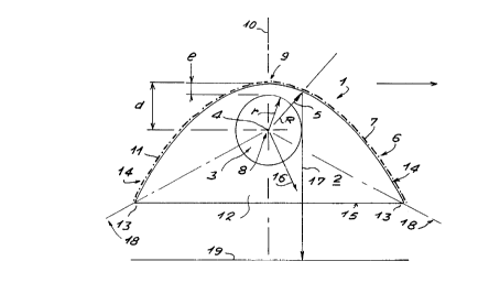
Figures 1 to 4 show a device 1 in cross section comprising a straight glass tube 2,
for example made of extruded quartz.
The tube 2 is drilled from end to end by a c ylindrical bore 3, of axis 4 and of radius r,
obtained by extrusion.
It is closed at each end by electrode-bearing plugs (not represented) which will be
described in detail further on, and contains an ionising gas, for example a mercury
iodide, at medium pressure, for example 3 bars, able to transmit ultraviolet radiation
5, when the tube is powered and it creates a plasma arc between the electrodes, in
a manner known in itself.
The tube 2 comprises a wall 6 provided with an external surface of at least partly
parabolic section, of equation y = x2 / 4f, f being the focal distance of the parabola
between the focal point 8 which merges with the axis 4 of the bore and the
generating line at the peak 9 of the parabola, situated in the axial plane of symmetry
10 of the bore.
CA 022~9~21 1999-01-04
12
The thickness of the tube in the axial plane 10, from the wall situated on the same
side as the generating line to the peak 9, being e and d being the distance between
the axis 4 of the bore and the generating line to the peak 9, it follows that:
d=fand, d=r+e(figure 1)
d ~ r + e (figure 2)
d = r (figure 3)
d ~ r (figure 4).
According to the embodiment of the invention of figure 1, the surface 7 is entirely
parabolic. It is covered, for example by cathode sputtering in a vacuum or any other
means known to the man of the trade enabling adhesion on quartz of a film 11 (inbroken line in figure 1) of material reflecting the ultraviolet rays (U.V.) transmitted, for
example of a metal layer of aluminium of a thickness of about one micron, for U.V. of
wavelength from 100 nm to 1 micron, for e,cample 360 nm.
The tube 2 is closed on the other side of the peak 9 in relation to the bore 3 by a
solid wall 12 extending between the ends 13 of the side wings 14 formed by the
sections of parabola symmetrical in relation to the axial plane 10.
The wall 12 comprises an external face 1';, transparent to radiation, for passage of
the directly transmitted rays 16 or of the ra~ys 17 reflected by the parabola.
It is recalled here, as a reminder:
- that the radiating energy (total or almost total) which irradiates from the focal point
8 of the parabolic curve, or as will be seen hereafter elliptic curve, or combined "arc
of circle and parabola" or combined " arc of circle and ellipse", is formed by the sum
of two radiating energies: the primary radiating energy, which irradiates directly in a
closed conical space 18 (in mixed line in figure 1) and whose limits are the ends 13
of the side wings of the reflector,
and the secondary radiating energy, which irradiates directly in a conical space open
on the reflection curve of the reflector to be reflected therein and return at best
perpendicular (arrow 17) to the product siituated in the irradiated plane 19 (case of
the parabola) or perpendicular to the tangents to the curved product to be treated by
irradiation (see hereafter the case of the ellipse),
- that the energy efficiency of an ultraviolet ray depends on the distance it covers
from its point of transmission to its point of receipt; by shortening this distance from
the point of transmission to the reflection plane (parabolic or elliptic curve) on the
... ...... .... . . . . .. .
CA 022~9~2l l999-0l-04
13
one hand, and from the reflection plane to the irradiated product on the other hand,
the invention therefore optimises the efficiency,
- that the sources whose luminance is independent from the direction obey
Lambert's law,
- that a better penetration depends on a high power density.
The intensity radiated in any direction is then equal to the product of the intensity
radiated in the direction of the normal to the radiated surface by the cosine of the
angle which this direction makes with the normal.
The face 15 of figures 1 to 4 is therefore flat and perpendicular to the axial plane 10.
In the embodiments more particularly described here, the transmitter/reflector device
is a monoblock entity, made of extruded quartz glass material, of very high
transparency quality in the 180 nm to 2000 nm passband and with a very low
fluorescence level, in which the transmitter and its reflector are intimately linked,
joined and inseparable, in such a way that the convex part, whose shape is
parabolic or elliptic, or presents another combined mathematical shape related
therewith, such as arc of circle + parabola or arc of circle + ellipse, is achieved to
become the reflecting surface.
The other part, facing the irradiated product, is transparent and arranged to direct
the whole of the transmitted radiation to the product, in such a way that the whole or
the essential part of the primary and secondary radiation arrives with parallel or
appreciably parallel fluxes perpendicularly to the irradiated product, according to
Lambert's law, in the case of a parabola, or in the direction of the axial plane 10
towards the second focal point of the ellipse in the case of an ellipse.
The geometrical shape of the dioptric surFaces, and in particular that of the lower
portion of the bore, implemented and generated structurally within the scope of the
embodiments of the invention more particularly described here, is designed with
reference to the geometrical focal point of the device comprising the tubes according
to the invention, a focal point in general merging with the axis of the bore, which will
therefore hereinafter be called focal axis.
Thus any light point originating from the focal axis irradiates radially as subsequently
represented in the figures.
On the other hand, it can be noted that any light point of the beam situated outside
the focal axis only partially complies with this radial irradiation mode corresponding
CA 022~9~21 1999-01-04
14
to the design of the dioptric surfaces. Only the radiation originating in the plane
passing through the focal axis corresponds to this design.
In the case of figure 1, the radius of curvature P of the straight transmitter is
therefore also the radius of curvature of the peak of the parabolic curve.
We therefore have R = r + e', r being, as we have already seen, the radius of the
cylindrical bore 3, which defines the light disk of the ultraviolet transmitter, and e' the
thickness of the quartz glass wall 11 of this same transmitter varying between e and
the maximum thickness of the wall in the corresponding axial plane.
In other words, the radius of curvature of the transmitter and that of the peak of the
reflector are identical and merged into one and the same.
According to the invention, they are moreover and advantageously of small size, i.e.
< 15 mm, advantageously < 10 mm, or even < 5 mm, even < 2 mm, for example
= 1.5 mm.
Referring to figures 2, 3 and 4, the radius of curvature R can also be the external
radius of the arc of circle of a dome 20 in the form of a portion of cylinder
symmetrical in relation to the axial plane 1() and of identical axis to the axis 4 of the
bore 3. The dome according to the invention is still covered on its external surface
with a reflecting material 11 (in unbroken line in the figures), for example aluminium.
As will be seen the rest of the external faces 14 of the parabolic wings may be either
also covered with a reflecting material, or be deprived thereof beyond a certain angle
of centre a5 corresponding to an angle of limit incidence aL, in which case reflection
of the rays transmitted by the tube will take place by dioptric refraction, according to
a particularly advantageous embodiment of the invention.
The arc at the peak of the parabolic curves is for its part represented in an unbroken
line 21 (virtual state) in figures 2 to 4.
In figure 5, another embodiment of the invention has been represented comprising a
dioptric cavity 22 formed by a longitudinal slit comprising a concave upper face 23 in
the form of a cylindrical portion, of axis 4 and of external radius equal to r + e.
The cavity 22 comprises two side faces 23' and 23" parallel to the axial plane 10 and
inscribed in the angle a2 defining the dihedron in which the rays would be entirely
reflected by the dioptric wall 15 in the absence of cavity.
The cavity also comprises a lower face 24 in the form of a curve whose equation is
determined according to the laws of optics to obtain a beam of rays 25, transmitted
. . .
CA 022~9~21 1999-01-04
to the support and conveying plane 19 of the products to be dried, which is as
parallel as possible.
In this particular case, the curve is a portion of cylinder of radius R' ~ R, with R = r +
e.
In case of absence of a partial cylindrical dome (figure 1) or if the arc at the peak of
the latter is less than 2 x a5 the rays inscribed in the angle a5 are totally or at least
partially reflected on the parabolic curve (this will also be valid in the case of an
elliptic curve as will be seen hereafter) and pass again inside the light disk, defining
an angle with the circular diopter 26 (figure 5) which is variable according to their
position.
They are then refracted in the surface of the luminous disk 27 elsewhere than on the
transmission focal point, then pass through the circular diopter 28 again in the other
direction according to variable angles of incidence and refraction, distributing the
radiation in different directions from those normally reflected by the parabolic (or
later elliptic) curve.
It is therefore to minimise the dispersion of this radiation that the invention proposes
to replace the parabolic or elliptic curves inscribed in the angle a5 (figures 2 to 5 and
figures 7 to 18 B) by the dome 20 of arc of circle cross section or dome in the form
of a portion of cylinder whose geomelric centre is on the focal point of the
transmitter/reflector.
All the rays transmitted in the inscribed angle a5 (which will always be less than 90~)
from the axis of the bore are then thereby reflected on the back of the cylindrical
dome 20 covered with reflecting material, and behave as a light image which has
been turned to radiate towards the frcnt of the transmitter/reflector inside theinscribed angle (a12 + a3), defining an inverse light image as if these same rays
came from the focal point or axis of the bore, and were only affected in their energy
value with a reflection coefficient of the re!flecting material applied to the back of the
dome 20.
Thus the secondary radiating energy originating from the inscribed angle a5 is added
to the primary radiating energy inscribed in the angle (a,2 + a3), inside which the rays
are all directed towards the plane 19 situated at the front of the transmitter/reflector.
At this level, all the radiating energy normally inscribed over 360~ is therefore
contained in the angle (a12 + a3), and is then divided into two parts, i.e. the radiation
_ .. . .. . . .
CA 022~9~21 1999-01-04
16
according to the inscribed angle a3, and the inscribed radiation according to the
inscribed angle a12
The embodiment of the transmitter/reflector device according to the invention
corresponding to figures 6 to 13 presenting an at least partly elliptic reflecting
surface 31 will now be described, in which d = r + e (figure 6); r ~ d ~ r + e (figures 7
and 7A); d = r (figure 8) and d < r (figure 97.
Here again the transmitter/reflector device is advantageously provided with a portion
of cylindrical dome 32 covered with a fine layer 33 of reflecting material (in broken
line in the figures), for example aluminium
More precisely the device 30 comprises a cylindrical bore 34 and a solid quartz glass
wall 35 which joins the wings 36 of the reflecting surface of elliptic cross section or in
the shape of portions of ellipse, for example a half-ellipse of equation:
2~2 y2
(FF +2d) (FF'+2d)2 (_)2
F and F' designating the focal points of th~e ellipse.
As in the case of figure 1, figure 6 shows a reflecting surface without upper dome,
entirely covered with a layer of reflecting metallic material which concentrates the
rays transmitted by the tube radiating towards the second focal point F'. In the case
of figures 7, 8 and 9 as in the case of figures 2, 3 and 4, only the cylindrical dome
32, and possibly a portion 36 (figure 7) of the elliptic surface directly next to the
dome with which it is joined is covered with reflecting material.
The wall of the dome therefore sends an inverse radiating image back to the focal
point F, which retransmits a reflected ray to the elliptic walls as if this ray was
originating from the focal point itself, with the same wavelength as the primary ray
transmitted with energy E, but with an energy E' ~ E due to the absorption linked to
the coefficient of reflection of the reflecting material deposited on the back of the
dome.
The wall 3~ is bounded towards the curved product to be treated 37 by a surface 38
of curved cross section arranged to be perpendicular to the largest number of rays
originating from inside the device, to prevent them from being deviated, in a manner
known to the man of the trade applying the laws of optics.
CA 022~9~21 1999-01-04
17
An example of calcuiation of the angle aL is given hereafter.
In the embodiments of the invention more particularly described here, with upperreflecting dome of a determined angle in the centre aS which will be specified
hereafter, the remaining part of the parabolic or elliptic reflecting surface is not
covered with reflecting material, reflection of the rays transmitted by the plasma disk
on this remaining part, i.e. in the cone of angle a3 being performed by dioptricrefraction, due to the different refractive indexes of the two refringent media which
are the quartz and the surrounding gas.
However there exists a limit angle aL which will depend on the wavelength of theultraviolet rays transmitted and of the precise values of the refractive indexes of
each of the media, above which any incident ray which meets the dioptric reflection
curve 14 or 31 is fully reflected.
This limit angle aL enables the above-mentioned angle at the centre aS of the dome
or portion of cylinder 20 or 32 to be determined so as to optimise the device so that
dioptric reflection is used to its maximum.
Indeed, there is then no energy loss of the secondary radiation energy transmitted in
relation to the primary radiation, which presents a great advantage.
Thus, the dioptric reflection fully restores l:he energy of the wavelengths lower than
250 nanometers which are often completely absorbed by the photoinitiators used on
the products to be dried.
Optimising restoral of the energy of th~ese wavelengths therefore considerably
speeds up for example the polymerization process of the treated ink, and therefore
the drying speed by factors much larger than the simple ratio of the energies.
On the other hand, reflection by a reflecting surface in general made of aluminium,
which absorbs the energy of the wavelengths less than 250 nanometers is less
favourable, although not excluded by the invention.
The invention therefore proposes a transmitter/reflector device:
- whose shape of the dome in portion of a cylinder and that of the parabolic or elliptic
reflecting surfaces of the wings,
- the refringence indices of the quartz and surrounding gas used,
- and the reflecting material used
are arranged to enable all or appreciably all of the rays of determined wavelength
and energy to be merged in a single unified and controlled, homogeneous flux,
according to the required treatment defining the photochemical parameters to be
CA 022S9S21 1999-01-04
18
retained to dimension said device, in an appreciably single direction, towards the
product to be treated.
In the case of a parabolic transmitter/refl~ector device, the primary and secondary
rays must be perpendicular to the irracliated plane, with a cosine equal to 1
according to Lambert.
In the case of an elliptic transmitter/reflector device, the rays are directed towards
the focal point F' of the ellipse.
The invention also proposes (figure 10, to be compared with figure 5) a device of the
type of figure 9 comprising a dioptric cavity 39 further improving the optical
equilibrium of the light disk, with a shape c alculated in a similar way to the cavity 22
of figure 5.
More precisely, the behaviour of the light rays within the scope of the device of figure
10 will now be described in detail.
This device present a combination arranged so that all the radiating energy is
contained in the angle a,2 + a3, as has already been seen with reference to figure 5.
The face 31, inscribed in the angle a3, then receives all the radiations comprised
between the limits of the rays 40 and 41.
These light rays convey their energy in a refringent medium which is quartz, whose
refraction coefficient value depends on the.~ wavelength passing through it.
They then meet a dioptric curved surface whose second refringent medium is air or a
gas (for example a neutral gas).
Thus, after the choice has been made on the wavelength(s) to be used and after the
gas constituting the second medium has been determined, the limit angle of
incidence aL (such that any incident ray which meets the curved dioptric reflection
surface 31 is fully reflected) is calculated, and the angle at the centre a5 of the axis
merged with the axis of the bore is deduced therefrom according to the equation of
the reflecting surface and the laws of optics.
An example of calculation of the angle aL is given hereafter.
Likewise, with reference to figure 5, by constructing the curve of the parabola as that
of the ellipse, and as has been seen, there exists a mathematical construction of the
curves such that the limit angle of incidence aL is the meeting point of the curve 20
or 42 as an arc of a circle with the curve 14 or 31 as a parabola or ellipse.
Here again the performance acquired is then remarkable knowing that:
CA 022~9~21 1999-01-04
- the polymerization rate of an ink or a varnish is closely linked to the reactivity of
these photoinitiators used in this product,
- the influence on the photoinitiators is essentially due to the energies borne by wave
lengths less than 250 nanometers,
- the metallic reflection coefficient for a treated aluminium to be ultraviolet reflective
is about 0.4 for wave lengths comprised between 180 and 270 nanometers, and
about 0.85 in the mercury spectrum, i.e. 360 nanometers.
For the same level of reactivity, three times more power is therefore required for a
known transmitter of the prior art, called "without ozone", than for a transmitter called
"with ozone".
Whatever the transmitted wavelengths on the other hand, the reflection coefficient
on a dioptric surface is always equal to one in the direction of propagation of a ray
moving from the solid transparent medium to the boundary of the gaseous
transparent medium.
In the embodiments more particularly described, the back of the parabolic or elliptic
curves under aL not being covered with a reflective coating, this advantage is
therefore to be found.
Figure 7A shows an embodiment of the invention improving the performances of thedevice according to the invention even further using dioptric reflection.
It can in fact be noted that, for all the rays inscribed in the angle a2, the curve 38
functions like the curve 31.
Indeed, the rays according to a2, bet~,veen the ray 43 and the rays 44, reach the
curve 38 with an angle of incidence greater than the limit angle of the two refringent
media.
The reflection is therefore total, the reflection coefficient being equal to 1.
Beyond this angle a2, in the direction of lhe axis 45 of the ellipse for example, the
ray 46 goes off obliquely towards the outsiide.
But in the case of total reflection, the radiating energy is then entirely sent back onto
the portion of curve formed by the parabolic 14 or elliptic (more particularly described
here) wings to give the reflecting surface 31, where a new angle of incidence isclose to 0.
The following situation is then observed: the portion of curve 47 operates in
reflection for all the rays transmitted in the angle a3 and, at the same time, in
transparency for all the rays transmitted in the angle a2.
~ , . . . . . . ..
CA 022~9~21 1999-01-04
The rays transmitted in the angle a2 exit by transparency from the
transmitter/reflector in the portion of curve 47 and are then sent back by reflection
obstacles 48 for example metallic, in the form of inclined longitudinal plates, flat or
curved, according to the directions which are to be given to the reflected rays 49.
Likewise the use of a dioptric cavity may or may not be combined with the reflection
obstacles 48.
The above comments and compiementary elements are naturally also applicable to
parabolic construction.
Another embodiment of a device according to the invention has been represented in
figure 11 with a dome in the form of a cylindrical portion of different thickness _, i.e.:
with e ~ R, where R is the external radius of the bore cylinder, as indicated by the
mixed line 51, with e = R by the broken line 52 and with e > R, for example e = 2R,
by the unbroken line 53.
Figure 12 shows a device 30 whose bore '34 comprises an internal face 54 provided
with two longitudinal grooves 55 of cros's section appreciably in the shape of atriangle of height for example < 1/5 of the diameter of the bore, for example equal to
1/10th inscribed in the angle a2, whose external side 55' is parallel to the axial plane.
The rays 43 and 44 bounding this angle a2 and the curve of the grooves 55 thus
defines a portion of energy which irradiates on one side the first circular diopter 56
formed by the ultraviolet light disk (first relringent medium with n = 1) on the quartz
glass (second refringent medium with n = 1.5) and is diverted the other side by the
side faces of the grooves towards the side walls 31.
More precisely the grooves 55 each comprise a side face parallel to the axial plane
10 and inscribed in the angle a2 defining t.he dihedron in which the rays are entirely
diverted by refraction onto the dioptric reFlection curves 14 for the parabolic curve
device and 31 for the elliptic curve device l'figure 12).
Figure 13 shows an altemative embodirnent of the device 30, comprising a bore
provided with a partially recessed lower part 60 forming a convex boss 62 on thelower intemal face 61 corresponding to the angles a12 and whose radius of curvature
R' is different from R in such a way that the rays refracted onto the dioptric curve 62
are then for example convergent.
The whole of the radiation inscribed in the angle a1 + a2 = a12, which defines aportion of energy irradiating the first diopter 56, also defines the portion of curve 62,
of the recess 60, in such a way that all the refracted primary rays are reoriented
, .... . . . ..
CA 022~9~21 1999-01-04
either to be directed to the virtual focal point F' in the case of the ellipse or to be
directed perpendicularly to the plane to be irradiated in the case of the parabola.
The whole of the rays inscribed in the angle a2 define a portion of energy irradiating
the first vertical diopter parallel to the axis of the recess 60, in such a way that all the
refracted primary rays are reoriented to be directed onto the dioptric reflection curves
14 for the parabola, 31 for the ellipse, where, on reflection on said dioptric curve,
they appreciably take the same path as the reflected rays originating from the angle
a3~
Thus, unlike known devices where the transmitter and reflector are physically
separated and for which two sorts of directed rays can be distinguished, which are
the primary rays and the secondary rays, the invention proposes a device which
enables the whole of the primary radiation and secondary radiation to be united in a
single homogeneous, unified and controlled flux in directions appreciably single and
identical.
A shape of the light cross section of the beam is advantageously sought for suchthat the light half cross section situated on the side of the angle a5 is equal or
appreciably equal to the light half cross section situated on the side of the angles a,,
a2 and a3.
As has been seen (figures 5 or 10) it is also possible to modify the dioptric curve 15
or 38, to reorient the radiation in such a way that the refracted rays originating from
the corrected dioptric transparency curve are even more parallel to one another and
perpendicular to the irradiated plane according to Lambert, or on the contrary are
reoriented so as to obtain a radiating flux converging towards a virtual focal point F',
or, inversely, a divergent radiating flux, by adding a dioptric cavity 22 or 39, in a
manner within the scope of the rneans of the man of the trade.
The circular dioptric curve 65 is the geometric extension of the circular metallic
reflection curve 11 or 42, in such a way that (cf. more precisely figure 11) any ray
which leaves the focal point (like any light ray on this same trajectory) passes via the
first circular dioptric curve 65 and the second circular dioptric curve 66 being diverted
towards the virtual focal point situated in the axial plane.
All the rays reach the face 15 or 38 within the limits of the inscribed angle a1 in such
a way that the primary rays all arrive perpendicular to the second diopter 67 (figure
11).
.. . _ , . . ...
CA 022~9~21 1999-01-04
In the case of the ellipse, it is possible to modify the dioptric transparency curve
(mixed line 68 in figure 11) even further l:o reorient the secondary rays originating
from a2 and those originating from a3 in such a way that all the rays refracted on the
corrected dioptric transparency curve 68 reconstitute a parallel radiating flux
perpendicular to the irradiated plane with a cosine equal to 1 according to Lambert.
It is also possible, in a manner within the scope of the means of the man of the trade
using the laws of optics, to modify the dioptric transparency curve 15 of a parabolic
transmitter/ reflector (figure 5) to reorient all the refracted rays onto a corrected
dioptric transparency curve (not represented) for example reconstituting a radiating
flux converging towards a virtual focal point F' or a divergent radiating flux.
The invention also proposes (figures 14 to 18 B) a device 70 comprising a cylindrical
tube 71 drilled from end to end with a cylindrical bore 72.
The tube is equipped with two longitudinal side lugs 73 of intemal surface 74 and
extemal surface 75 presenting cross sections in the shape of portions of parallel
parabolas, the extemal surface 75 consl:ituting the portion of parabolic reflecting
surface of the wing according to the invention.
The lugs have a width for example equal to the radius of the bore.
They are symmetrical in relation to the axial plane 76 passing through the generating
line at the peak 77 and the focal point 78 rnerged with the axis of the bore 72.The lower face 79 of the lugs for the parabolic shape is perpendicular to the plane
78 and situated in a plane 80 (in mixed line in the figures) tangent to the lower
portion of cylinder of the tube 71 for example of thickness equal to half the radius of
the bore.
The upper part of the tube constitutes, as described previously with reference to
figures 2 to 4, an upper dome 81, the arc at the peak of the parabola being entirely
comprised in the thickness of the cylindrical wall (r < d < r + e) (figure 14), being
tangent to the bore 72 (d = r) (figure 15) or being secant to the bore (d < r) (figure
16).
In the embodiments of the invention more! particularly described here, e = r and the
distance between the ends of the lugs 73 is equal to 7.4r.
Likewise, and as previously described, the bore can comprise longitudinal grooves
82 of isosceles or equilateral triangular cross section to redistribute the rays of the
angle a2 either towards the inside as primary rays or towards the outside as
... . . . . .
CA 022~9~21 1999-01-04
secondary rays by dioptric or metallic refl~ection (figure 17), for example of height
equal to about 1/10th of the radius of the bore.
In the embodiment of figures 18, 18 A and 18 B, a longitudinal spur 83 of rectangular
triangular cross section is on the other hand provided, whose external side wall is
parallel to the axial plane 76, which enables recanting of the rays towards the axial
plane 76 or parallel to said axial plane 76 to be improved even further, by making
use of the laws of optics.
As an example, and with reference to figure 18, the calculation is given below
enabling the parabola of the reflecting surlace 84 to be constructed, for a radius of
the light disk r = 2 mm, a thickness of the quartz glass e = 2 mm and a refractive
index depending on the wavelength used.
It can be seen that for ~ = 200 nm, n200 = 1 551
~in a 200 = 1 = = 0.6447, a 200 = 40.14~
n200 1.551
and for ~ = 360 nm, n360 = 1.475
sina360 = 2 = 475 = 0.6779, a360 = 42.68~
We will therefore take for the calculations aL = 42~ as reflection limit angle for
wavelengths ~ < 360 nm.
The tangent to the parabolic curve being
tg - = tg42~ = 0.9,
it is also the derivative of the equation of the parabola: y' = 0.9.
Let us set down the equation of the parabcla
1 x2
Y a
This gives:
1 (S + ~2 = 1 (X2 + 2x~ + ~ )
a a
= 1 (x2 + 2x~X + ~X2) ~ Y
a
= 1 (x2 + 2~x + ~2) _ 1 X2
a a
= 1 (2x~x + 2~x2)
CA 022~9~21 1999-01-04
24
Which therefore gives:
2 aL
y' = --x = tg--
According to the definition given before R = r + e = 4 mm
sin 84~ = xT
We can then calculate the coordinates at the point T; i.e.:
XT = R sin 84~
= 4 x 0.9945 = 3.978 mm
For the coefficient "a" of the parabola this gives:
y' = --x = tg 2 atthepointT
a
and a = L x with XT = 3.978 mrn
tga 2
a=8.83
tg42~ = tg-- =0.9004
The equation of the parabola is therefore of the form
Y 8.836
The significant points of the curve are then:
- the point 8~ (XT;YT) of the dioptric tan~gent, with XT = 3.978 mm =~ then YT =
1.7909 mm
- the point 86 (X~ = ~;Yd of the generating line at the peak.
The distance from the focal point of the parabola to the peak of the latter (therefore
for x = 0) being
y = 4 with Xf = O
. .
CA 022S9S21 1999-01-04
This then results in Yf = 2.209 mm
- the point 87 (X,;Y,) of intersection of the axial plane 88 with the parabola with
Y, = 2.209 mm, whence X, = 4.418 mm
- the end point 88 (X2;Y2) of the lug 73 with Y2 = (2.209 + 4) mm then X2 = 7.4 mm.
Figure 19 shows a device 90 with a parabolic reflecting surface 91 of the type with
side lugs 92 as described with reference to the previous figures.
The cross section of the bore 93 is this time not circular but in the shape of atruncated circle whose upper parts 94 and lower parts 95, of cross section in the
shape of a half-moon are kept solid, made of glass, symmetrically in relation to the
plane 96 perpendicular to the axial plane 97 containing the generating line at the
peak 98 of the parabola.
It has been observed that such an arrangement enabled a considerable increase ofthe efficiency to be achieved, in the change ratio of the light cross sections, in
relation to a circular cross section 99 (in rrlixed line in figure 19), according to a law
of the type
rl (S1)
with S2 the cross section of the circle and S1 the cross section of the truncated
circle.
In this embodiment the angle a3 = a'3 + a"3 is such that (for the radius and thickness
values taken before with reference to figure 18)
cos a"3 = 9 = 0.9945 ~a"3 _ 6~
7-4 - 2-209 = 0836=, a'3 _ 40~
6.209
i.e. a3 = 46~
To re-establish the equilibrium of distribution of the rays reflected upwards, the wall
100 of the dome 101 of the device 90 presents a flattened surface 102 in relation to
that of a cylindrical dome 103 (in mixed line in the figure).
CA 022~9~2l l999-0l-04
26
Its equation is calculated so as to enable a return of the rays transmitted 104 from
the bore 93, in exactly reverse manner, the incident rays therefore having to strike
the reflecting surface 102 perpendicularly.
Figure 19 A shows another monoblock device 105 with cylindrical bore comprising
two lugs 106 of parabolic surface 106'. The lower face 107 is cylindrical, with an axis
identical to the axis of the bore, and joins the internal ends 107' of the lugs to one
another.
Figure 19 B shows a monoblock device 108 of the type described before with lugs
and cylindrical bore, comprising on its lower internal surface a recess 109 provided
with side faces 109' parallel to the axial plane and with a cylindrical lower face 109",
of radius equal to the external radius of the cap.
Here, the lugs have an elliptic surface, the lower face of the lugs being shaped as a
portion of a cylinder.
Another embodiment of a device 110 according to the invention has been
represented in figures 20 to 25 comprising a transmitter tube 11 made of tubularquartz, separated from its reflecting wings 112 and 113 made of metallic reflecting
material.
The transmitter/reflector couple nevertheless proceeds from the same geometric
arrangement as the transmitter/reflector devices described above, where reflector
and transmitter are securedly united to one another.
The reflector formed by the two wings 112 and 113 therefore presents a reflecting
geometric shape whose geometry combines the arc of circle with the parabolic curve
or with the elliptic curve.
The transmitter tube 114 for example cylindrical, is covered with a reflecting material
115 as shown in the figures, i.e. with a slight angle overlap with the wings.
It can adopt different shapes and be:
- a circular transmitter with electrode chamber, according to the invention,
- a conventional transmitter, and/or
- a transmitter excited by microwaves.
Figures 21 to 24 schematically show the respective positions of the tube 114 in
relation to the generating line at the peak 116 of the parabola partially forming the
wings, for example made of aluminium, which is also true in the case of the ellipse.
The separation between the transmitter and reflector here enables a circulation 117
of the coolant fluid.
CA 022~9~21 1999-01-04
Figure 25 shows a device 118 with an ellipsoid reflecting surface, equally applicable
to the parabolic shape.
Figure 25 shows two symmetrical wings 120, terminated at the top part by a portion
of cylindrical dome 121 and separated frorn one another by a longitudinal slit 122,
through which a coolant fluid 123 can be inlet.
The top 124 of the cylindrical transmitter tube 125 is coated with a metallic layer 126
so as not to leave any escape angle for the transmitted rays, there being an overlap
between the end of the portion of cylindrical dome 121 and said also partially
cylindrical metallic layer 126.
Figures 26 A, 26 B and 26 C show three ernbodiments of cylindrical tubes coated on
the upper portion with a reflecting layer according to the invention.
Figure 26 A shows a tube 127 with a bore 128 in the shape of a cylinder truncated
by a lower plane 129 perpendicular to the axial plane 130, for example situated at a
distance equal to half the radius of the axis 131.
Figure 26 B shows another transmitter tube 132 comprising a recess 133 on the
lower face 134 of the cylindrical bore. The recess comprises side walls parallel to the
axial plane 135 and a lower face 136 in the form of a port~on of cylinder of radius
equal for example to the external radius of the tube.
A transmitter tube 140 according to the invention has been represented in figures
27 A, 27 A', 27 B and 27 C with partially dissociated reflectors, of parabolic cross
section shape.
More precisely the tube 140 (cf. figure 27 A) is appreciably cylindrical, its upper part
141 and its bore 142 being of the flatlened or truncated type described with
reference to figure 19.
The upper part 141 is covered with a reflecl:ing layer 143.
The tube (see figure 27 A') can comprise a lower portion 141' whose external
surface 141" enables the rays refracted bly the truncated cavity of the bore to be
diverted in parallel fluxes for example or, in the case where the same convex shape
is used but more accentuated (with a smaller radius of curvature), a convergent flux
to be diverted to the second focal point F', according to the laws of optics.
The wings 144 entirely at a distance from the transmitter tube are for example
mechanically fixed slightly prestressed so as to keep them in mathematical position
by a pin screw 145 (cf. figure 27 B).
. . .
CA 022~9~21 1999-01-04
This screw is fixed in a groove 146 of the dryer support structure which may be of
extruded aluminium profile. A hypothesis of cooling sweeping 148 is shown in figure
27C.
Figure 27 D shows an acceptable alternative version of the invention, comprisingportions of flat, rectangular wings 149 extending along the tube and at a distance
from the latter or not, the portions are tangent andlor appreciably identical to the
parallel or elliptic section of the wings of the previous figures.
These portions according to the invention can therefore be appreciably assimilated
to a parabola or ellipse, but easier to manufac:ture.
Several embodiments of a transmitter 150, 151, 152, 153 usable with the invention
have been represented (figures 28 to 31 A).
In these embodiments more particularly desc:ribed, a light disk of internal diameter
"ID" of about 4 mm (and advantageously less) is provided for the whole radiatinglength ''Luv''.
At each end, a chamber 154, 155, 156 is provided corresponding to the housing ofthe electrode (when it exists) and to the potential fouling and devitrification zone.
In figures 28 and 29 the diameter of the chamber 'lDcell is enlarged up to the usual
value of 11 mm which, by experience, is recognised as being sufficient for correct
operation of the electrode and for the mechanical strength of the quartz enclosure.
In figure 30, a structure with no electrode has been provided, for example in case of
20 external excitation by microwave.
In the course of operation of a known transmitter, a milky zone is observed around
the electrode which becomes progressively opaque over a certain length "b~ll, which
is classically the length of the electrode chamlber.
This length begins at the foot of the electrode and ends with the invention at the
reduction of the intemal diameter "ID".
To remedy this, it is therefore also proposed to provide a coating of reflectingmaterial 157 over the whole external periphery of the chamber, designed to maintain
a certain radiating temperature for the elec:trode. This coating is represented in
dashed lines in figures 28 to 31 A.
AMENDED SHEET
CA 022~9~21 1999-01-04
The invention enabling drying of an ink or a vamish, by means of an ultraviolet
transmitter, which does not depend so much on the increase of the linear powers as
on the modification of the shape of the light disk and/or on the decrease of its cross
section, this leads for the same result, to said linear powers being able to be
lowered, which means that at low power (~ 30 W/cm) no electrode chamber, even
with a very small diameter (figure 31) is required.
An example of manufacture of a transmitter/reflector device is described hereafter,
for the purposes of illustrating its ease of achievement, with reference to figure 28.
The transmitter/reflector device 150, also of the type of figure 10, comprises a body
160.
The end 161 of the body is first heated and is then crimped to the diameter of the
electrode plug 162, achieved in the usual manner.
The plug comprises a ceramic end 163 as used for example by the Philips Company
on its own manufactures.
Assembly in fact takes place in three stages:
- The end of the transmitter/reflector device is prepared, over a length ~LCe~ by
cutting by milling at the level of the dioptric cavity, which is easy since the tube
forming the transmitter enclosure is practically completed in its cylindrical
configuration at the time of threading; then the quartz is heated to its softening
temperature; the diameter is then flared to give it the extemal diameter of the
electrode plug;
- The electrode plug 162 is then mounted on the body 160 of the transmitter/reflector
device by heating; complete fusion of one part on the other is thus created according
to the same method as that used by the glass-maker to close the end of the
transmitter.
- Finally the ceramic end part 163 is fitted on the electrode plug after electrical
connection has been made by welding.
The mercury is for its part inserted according to the usual manufacturing methods.
A reflection layer coating is then applied to the transmitter and to the ends of the
transmitter/reflector and/or partly or totally on the wings.
On account of the low linear powers (< 30 Watts/cm), due to the large increase of
the energy efficiency, it is possible, for transmitters of radiating length ''Lw'' variable
up to a little more than one metre, to increase the linear voltage up to a value of
30 volts/cm (i.e. 3000 volts in supply voltage, a value still used in the profession)
~, , , . , . _
CA 022~9~21 1999-01-04
which enhances the quality of the ultraviolet arc while preserving a current of
maximum intensity of about 1 A.
The more conventional powers of 80 Watts/cm can naturally also be adopted,
suitably modifying if necessary the ventilation required for cooling.
Figure 32 shows in cross section several embodiments of the invention, whose
transparent face presents different forms ac:cording to the desired applications.
Thus, figure 32 A shows a cross section in the shape of a half-moon.
Figure 32 A' shows the same type of cross section, but with a lower cylindrical cap of
the type described with reference to figure l9 A.
Figure 32 B shows a bore of transverse cross section in the shape of an eye, thelower wall being convex.
Figure 32 C shows an embodiment of a device of the type of figure 1, with a large
thickness of lower wall and a parabolic refle!cting surface.
Figure 32 D gives a version with a bore of boomerang-shaped cross section, with a
reflecting wall parallel to the bore.
Figure 32 D' gives another version with three bores, one central cylindrical bore and
t~vo side bores symmetrical in relation to the axial plane, of appreciably triangular
cross section and whose walls are parallel on the one hand to the external walls of
the device and on the other hand to the walls of the bore.
Figure 32 E shows yet another embodiment of a device, symmetrical in relation to an
axial plane in the form of two portions of opposite parabolas or ellipses with
cylindrical bore.
Figures 33 to 37 represent apparatuses comprising one or more devices
corresponding to one or more of the types described above.
Figure 33 is a schematic cross sectional view of an apparatus 200 according to the
invention able to comprise two identical devices 201 situated on two opposite walls
of a support structure 202.
With reference to figure 34, the invention therefore proposes an ultraviolet drying
apparatus 200 whose support structure 202 is formed by a profiled tube 203 made
of extruded aluminium which may be of square or rectangular, circular or ovoid
shape, and comprising on its y-axis a single device or two devices 201 in opposition.
More precisely, the transmitter/reflector device 201 of figure 33 is mounted in the
profiled aluminium structure 203 for whichl the drawing of the internal shape called
"cradle" 204 is identical to that of the convex shape 205 of the device.
~ . . . .
CA 022~9~21 1999-01-04
31
A ventilation space 206 of about 1 mm is reserved between the two shapes.
The ventilation space is smaller than the air cross section of the profiled section so
as to cause an appreciable pressure loss at the bottom of the device 201 and thus
force the air flows 207 to become uniforrn at the back and on each side of the
radiating device.
This "cradle" shape comprises at the peak a longitudinal slit 208 whose width isvariable according to the direction of the ventilation in such a way that the air flow
which sweeps the back of the device is conistant over the whole length.
The transmitter/reflector device 201 is moreover held in position geometrically
centred in relation to the profiled aluminium section by means of a securing part 209
fixed to each end of the device.
When the device is assembled, the securing part 209 slides simultaneously in thetwo intemal grooves 210 of the profiled section and in the ceramic cylindrical end
part 211 of the device.
It can be noted that the securing part 209 is for example formed by three floating
elements enabling the transmitter/reflector device to be kept positioned in the centre
of the aluminium profiled section while accepting manufacturing tolerances.
Its fixing is achieved by means of two bolts 212 housed and tightened in the bottom
internal grooves 210 of the profiled section.
A cover 213 is moreover added at each end of the device enabling the longitudinal
ventilation which is conveyed in the extrucled profile as if a normal aeraulic sheath
was involved, to be separated from the bransverse ventilation which is distributed
with appreciably laminar flow in the reserved space at the back 214 of the
transmitter/ reflector device.
Its assembly and mechanical fixing proceeld from the same principle as the securing
part 209.
At the ends of the device, there are slid in the top and bottom grooves 215 covers
216 which, once in place, position the device longitudinally in the profile.
Finally and for example in the transverse direction of the device, housed in the two
bottom grooves, on each side, there are fixed two small pointed spacing wedges 217
to prevent thermal bridges.
These small wedges are designed to preserve the ventilation space and to keep the
device 201 centred in the profile according to the two axes.
.. . . ..
CA 022~9~21 1999-01-04
32
The extemal cover is for its part perforated at the level of the end lengths of the
device with a longitudinal slit (not represented) of a length smaller than ~LE~ (length
of the end part) and of a width of about 3 mm to enhance the temperature drop ofthe ceramic end part at the foot of the electrode according to a gradient down to
300~C.
The external surface, on the width side of the profile, is provided with small grooves
218 which are as many inclined surfaces designed to prevent uncontrolled outlet of
diffuse reflected rays.
The width opposite the radiating part is arranged with a narrow housing 219 (figure
35) designed to receive the electrical logistics (not represented) necessary for the
dryer such as the wiring of the transmitters and that of the thermostatic and
photometric control elements.
This same width may be envisaged to receive a possible second transmitter/reflector
device 201.
Its cradle shape can also be used as a housing for the electrical wiring in use with a
single transmitter/reflector.
On the two lengths of rectangular profile, on the external wall, there are also
arranged rectangular grooves 220 enabling several dryers to be associated at thesame time by means of spacers 221 whose variable width and shape enable a set ofjoined or separate dryers to be constructed, with an arrangement which may be
straight or circular-shaped (figure 37), or square, or rectangular, or polygonal.
The spacers 221 thereby become the extemal and intemal walls of the processing
enclosure. Furthermore, the homogeneous shape of the profile enables a set of
dryers to be just as easily assembled "head-to-tail" (figure 36) to achieve a minimum
space occupation to process two sheets in "forward and return" manner (arrow 222).
Finally, at each longitudinal end of the dn/er (figure 34), the connection 223 of the
ventilation duct is located on one side, alnd the electrical connections 224 of the
transmitter, the,ll,oslclic relays, and photometric cell, on the other side.
The invention is applicable to non-fluorescent low pressure transmitters and forlamps radiating in visible light.
As far as the ventilation at each end of the transmitter is concerned, over the whole
length ~LCE~ the opening of the structure t.o air is much larger so as to enhance the
temperature drop to values lower than or equal to 300~.
,._ , , . ., ~. ,
CA 022~9~21 1999-01-04
It can be noted that the radiating source is located in the circular curve 20 of the
device (figure 2), where the temperature is the highest, whereas the two ends in the
form of wings 14 are swept by a smaller extemal ventilation to take account of the
expansion differences and to minimise the intemal tensions.
Advantage is taken of the low expansion of quartz to ignore the temperature
differences which exist between the circular enclosure of the tubular part called "of
the transmitter" and the external ends of the elliptic or parabolic part "of thereflector".
As a reminder, the distribution of the ventilation designed to maintain the operating
temperatures at different points of the radiating elements is known to the man of the
trade who plays on the dimensions of the holes, their position, on the choice of fan
and its characteristics (flowrate/pressure) to model the aeraulic currents to the
thermomechanical necessities of the radiating element.
On account of the good mastery of the air flows circulating around the radiatingelement with the invention, the flowrate necessary for the thermal equilibria remains
less than 50 m3/h/kW.
It is interesting here to set out five advantages provided by the transmitter/reflector
device according to the invention:
- At the same polymerization capacity of a known drying system, the blowing
ventilation necessary for cooling of the radiating element is considerably reduced to
the point of being able to be easily integrated in the lost volumes of the printing
machine.
- The transmitter/reflector device not having any mechanical reflection surface or
radiating surface swept by the ventilation, Filtering of the air is not necessary.
- A consequence of the second advantage, the radiating element not having any
mechanical reflection surface in air, degrcnding of the reflection coefficient in time is
impossible and its reflecting quality is not ilmpaired.
- Consequently, due to the almost total absence of air flow under the radiating part,
except by Venturi effect of the running sheet, the quantity of ozone is imperceptible
to the measuring elements, and extraction ventilation being of no purpose, the risk of
oxidation of the metallic parts of the machine becomes negligible.
- Due to the small quantity of ventilated air, an antioxidant aeraulic cover canmoreover be provided, if the product requires, by replacing, for example, the air by
nitrogen.
... ..
CA 022~9~21 1999-01-04
34
The numerous advantages of the invention are notably due to the following seven
parameters:
- the reduction of the light cross section,
- the non-circular shape of the light disk,
- the reduction of the path followed,
- the absence of ozone,
- the dioptric reflection curve, with a reflection coefficient 1,
- the dioptric transparency curve, with a cosine of about 1,
- the high power density.
To sum up and moreover in non-exhaustive manner, the advantages of the inventionare the very low linear power for identical photochemical results, consequently and
in the same proportions, the reduction of the stray thermal energy; the directivity of a
homogeneous flux parallel to the constant power density; the unimpairable nature of
the reflecting surface, and consequently the absence of filtering device; the absence
of measurable ozone; the low cooling ventilation which makes the aeraulic
installation insignificant; the greatly reduced electrical arrangements and cabinet
dimensions; the extreme simplification of manufacture of the dryer; the greatly
reduced dimensions of the dryer in relation to the competition; the installation of the
ultraviolet dryer directly in the inking or varnishing station; the transmitter/reflector,
the only component with a lifetime; the elimination of the buckling effect called
"banana" effect, etc.
Figures 38 A, B and C show top views of l:he apparatuses according to the invention
comprising several apparatuses 200 arranged to dry a sheet of products 225.
Figure 38 A shows apparatuses 200 ;3rranged perpendicularly to the running
direction 226 of the products in left/right altemation, with a slight overlap at the
centre of the product.
Figures 38 B and C show apparatuses 200 arranged obliquely in relation to the
running direction with an angle comprised between 5~ and 20~, advantageously 15~to distribute the rays homogeneously.
Figure 39 shows three distribution curves of the light density in a cylindrical tube
300.
The cylindrical tube 300; for example of small diameter (< 10 mm), is placed at the
focal point 301 of a reflecting parabola 30,2 (cf. figure 40A).
CA 022~9~21 1999-01-04
The curve 303 shows an appreciably homogeneous distribution, the plasma 303' (cf.
figure 40B) occupying the whole of the volume of the tube, for example with a linear
voltage, for a tube a few centimetres in len!3th, of 5 Volts/cm.
The curve 304 shows the density distribution 304' for a voltage between electrodes
of 30 Volts/cm and curve 305 the distribution of the plasma 305' for a voltage of 100
Volts/cm.
In this case the plasma beam is almost linear, with a cross section close to a pin-
point, and away from the walls 306.
In the case of figure 40B, the reflecting wall 307 is of hyperbolic transverse cross
section, the rays 308 emitted by the beam being sent back to the focal point 309,
without interferences with the beam 305'.
Figure 41 shows a device 110 comprising a cylindrical tube of constant cross section
111 of small diameter, for example smaller than 9 mm, provided with two wings 112
of transverse cross sections in the shape of a portion of ellipse, covered by a
reflecting material, separated at their peak by a slit 113, for example with a width of
from 1 to 5 cm.
The device comprises a horizontal flat plate 114, facing the tube 111 entirely at a
distance from the wings.
The distance d between axis and upper generating line of the ellipse is such that d =
f and d < r + e + 1 mm (f = distance to the focal point; r = radius of the tube;e = thickness of the tube), said plate being reflecting of the rays transmitted by a
plasma beam 115 of diameter less than l:hat of the intemal bore of the tube. Theplate (sheet metal) acts as support for the whole of the transmitter/reflector.
It is situated at a distance h, for example from 10 mm to 3 cm, and is fixed forexample by spacers (not represented) on which the flat edges 116 of the upper end
of the wings rest.
The lowerface 117 of the plate 114 situated facing the slit 113 is rendered reflecting
by sticking, depositing or film casting of a reflecting material, orifices 118 for
passage of the cooling air 119 being provided on the sides.
Naturally, and moreover as results from the foregoing, the present invention is not
limited to the embodiments more particularly described, but on the contrary
encompasses all the altemative versions and in particular and for example those
where the cross section of the light disk is more flattened, or even laterally truncated.
. _, . . . , . . ~
CA 022~9~21 1999-01-04
36
The invention also relates to apparatuses which enable sterilization of the water
around an axis and drying of ink and vamish to be polymerized on wire products or
circular around an axis such as marking of electric wires, cables, rubber hoses, PVC
tubes, etc.
An ultraviolet transmitter/reflector according to the invention can thus be fitted on a
sterilization or polymerization chamber for example in opposition around a
transparent cylinder acting as sterilization or polymerization chamber.
The apparatus for processing axial products can for its part comprise several
radiating devices, for example three, five or seven, arranged regularly in a star
shape around a transparent cylinder acting as sterilization chamber.