Note: Descriptions are shown in the official language in which they were submitted.
CA 02259716 1999-O1-20
-2-
COMBINED CABLE MANAGER AND TABLE CONNECTOR
This invention relates to work station systems suitable for offices,
particularly such systems which employ elongate support beams and/or support
walls that are mounted on the floor and that extend horizontally.
A variety of work station systems for use in offices and other work areas
have been developed in recent years, many of these systems being designed for
the purpose of using office space more efficiently. Because modern offices
commonly require a considerable amount of electronic office equipment and
cables and wires to operate and support same, modern office systems must be
adapted to accommodate this type of equipment and must make it easy for
workers and employees to use and operate this equipment in an efficient and
effective manner. In addition, work station systems must take into account the
need to have access to this electronic office equipment, including telephone
units and the wires and cables for same, for the purpose of providing
maintenance, repairs, and upgrades or changes to the equipment.
Work station systems suitable for an office which are based on an
elevated, horizontal, structural beam support are known and used in the office
furniture industry and these systems can be used to support electronic office
equipment and phone systems. One such beam-type work station system is
described in United States patent No. 4,838,177 issued June 13, 1989 to Nova-
Link Limited. This system is capable of mounting reasonably heavy electrical
communication and computer equipment along the rear of a horizontal work
surface. Support legs mount a beam of rectangular cross-section in a
horizontal
position above the floor while support brackets are detachably connected to
one
or both sides of the beam with the work surfaces being mounted on these
brackets. Although this known work station system works reasonably well, the
work surfaces provided by this system are not generally or easily adjustable
or
movable either in a horizontal direction or in a vertical direction.
CA 02259716 1999-O1-20
-3-
The applicant's co-pending Canadian patent application serial No.
2,207,344 filed June 9, 1997 describes and illustrates an improved beam-type
work station system which not only employs a horizontal support beam and
work surfaces mounted on at least one side of this beam, but also has a
primary
support wall capable of bearing reasonably heavy loads and mounted on top of
the beam in a generally vertical position so as to be supported by the beam.
This pending application also describes the use of a support wall extension
which can be mounted on top of the primary support wall so as to increase the
overall height of the support wall, which extension is detachable from the
primary support wall. Preferably the primary support wall and any extension
thereof have major surfaces thereof formed by metal panel members on which
office equipment or shelves can readily be mounted by means of horizontally
extending rails integrally formed on the panel members.
The aforementioned pending application also teaches the use of
adjustable support brackets that can be mounted on one or both sides of the
beam and that can be used to support not only electrically operated display
screens and/or computer equipment but also horizontal work surfaces.
However, although the support brackets are extendible to some extent in a
horizontal direction, thereby moving the work surface outwardly away from the
beam, any such adjustment does require some time and effort by the user or his
or her equipment provider and therefore any such adjustment would only be
carried out occasionally, possibly when the office was being reorganized or
when new office equipment was required. Furthermore, this known system does
not provide for any easy adjustment in the height of the work surface.
It is also known in the office furniture art to provide readily movable
tables and desks, often by providing wheels or rollers mounted on the bottom
of
the furniture or at the bottom of the legs thereof. A recent example of a
movable office desk with a keyboard support is that shown and described in
CA 02259716 1999-O1-20
-4-
U.S. patent 5,704,299 which issued January 6, 1998 to Haworth, Inc. This
keyboard support stand includes a support frame assembly and a height-
adjustable top work surface that is divided into two side surfaces. The legs
of
the stand extend upwardly from two horizontal base members which can have a
rollable caster mounted at one end thereof to facilitate repositioning of the
stand. A support foot is mounted at the end of the base member located away
from the caster. One known difficulty however with movable office furniture is
that they may not be suitable for computer and/or communication equipment
which can be quite delicate and easily damaged by movement. For this reason,
it is generally desirable to mount such delicate equipment so that its
position is
substantially fixed.
Another problem with movable desks and tables is that, if electrical
equipment is placed or mounted thereon, loose cables and wires for this
equipment can be a problem and can even create a safety hazard. There is a
clear need to reduce or avoid entirely any loose cables and wires and to
properly provide for conducting same to the desk.
Devices such as protective sleeves and conduits for protecting and
supporting electrical cable and wires are known in the cable and wire
industry.
For example, it is known to provide flexible, metal conduit which will protect
wiring as well as persons and equipment located in the vicinity of this
wiring.
Rigid, metal pipes can also be used along walls to conduct and protect wiring
and cable.
In particular, it is known to provide flexible, cable carriers for use in
conjunction with large machine tools that have a moving machine component.
One such cable carrier which is said to be self supporting is taught in U.S.
patent 4,658,577 which issued April 21, 1987 to A & A Manufacturing
Inc. This cable carrier is capable of carrying one or more cables or
conductors
which are provided to transmit energy to a moving machine member. The
CA 02259716 1999-O1-20
-5-
carrier is formed of a plurality of segments or lengths which can be of
similar
construction. Each segment has a generally rectangular cross-section with a
hollow interior. The segments are pivotable with respect to each other a
limited
amount to form a flexible tube which fully encloses the cables or wires and
supports same. The segments are preferably molded in one piece from a
suitable plastic.
Also it is known in the modular office furniture art to provide rigid
supporting walls that are mounted on the floor and not on a beam structure.
Such walls can provide conduits for electrical wires and cables that are
connected to office and computer equipment. Desk and shelving modules can
be rigidly connected to these supporting walls.
The present invention seeks to provide a work station system suitable for
an office which includes an elongate supporting structure and a movable desk
unit mounted on rollable members wherein the desk unit is connected by a
flexible cable and wire carrier device to the supporting structure and the
desk
unit itself is readily movable at least in a primary direction towards and
away
from the support beam.
The invention further provides a highly flexible and utilitarian work
station system for an office which includes a rigid, horizontally extending
supporting arrangement and at least one movable desk unit with the desk unit
or
units being movably connected to the supporting arrangement by means of one
or more flexible cable and wire carrier devices each of which in a preferred
embodiment includes an elongate carrier section made of a plurality of
interconnected links that are pivotable with respect to each other.
According to one aspect of the invention, a work station system suitable
for an office comprises an elongate rigid, horizontally extending supporting
arrangement adapted for support on a floor, this arrangement including a wall
structure that extends vertically, and a movable desk unit with a work surface
CA 02259716 1999-O1-20
-6-
thereon and rollable members mounted at a bottom end thereof. These members
rollably support the desk unit near the supporting arrangement. A flexible
cable and wire carrier device extends between the supporting arrangement and
the desk unit and is connected to both. This carrier device includes an
elongate
carrier section comprising a plurality of interconnected links that are
pivotable
with respect to each other in a single, vertically extending plane. The
carrier
device permits the desk unit to move in a primary direction towards and away
from the supporting arrangement and substantially prevents movement of the
desk unit in a horizontal direction perpendicular to the primary direction.
Preferably, the desk unit includes a desk top section providing the work
surface and the height of this desk top section is adjustable. The carrier
device
is connected to this desk top section.
According to another aspect of the invention, a work station system for
an office comprises an elongate, rigid, horizontally and vertically extending
supporting arrangement adapted for support on a floor, this arrangement being
adapted for supporting electrically operated office equipment. A movable desk
unit with a desk top section provides a work surface on top thereof and a
flexible cable and wire carrier device extends between the supporting
arrangement and the desk unit and is connected to both. The carrier device
includes an elongate, flexible carrier section comprising a plurality of
interconnected links that are pivtable to a limited extent with respect to
each
other. The carrier section provides protection for wires or cables extending
therethrough during use of the carrier device and has a desk end and an
opposite end, the desk end being connected to the desk unit at a connection
point located a substantial distance above the floor. The carrier device
permits
the desk unit to move towards and away from the supporting arrangement to a
limited extent.
CA 02259716 1999-O1-20
According to a further aspect of the invention, a work station system
suitable for office use includes an elongate horizontally and vertically
extending supporting arrangement adapted for support on a floor, this
arrangement including a support wall that extends vertically. 'The supporting
arrangement supports computer equipment including a central processing unit.
At least one electronic display screen is mounted on the support wall and is
operatively connected to the computer equipment. There is also a movable desk
unit with a computer keyboard provided thereon, this keyboard being connected
by wiring to the central processing unit. The desk unit includes rollable
members mounted at a bottom end thereof and rollably supporting the desk unit
near the supporting arrangement. A flexible cable and wire carrier device
extends between the supporting arrangement and the desk unit and is connected
to both. The wiring extends through this carrier and is protected thereby. The
carrier device permits the desk unit to move towards and away from the
supporting arrangement.
Again, the preferred cable and wire carrier device includes an elongate
carrier section comprising a plurality of interconnected links that are
pivotable
with respect to each other.
Further features and advantages will become apparent from the
following detailed description of a preferred embodiment taken in conjunction
with the accompanying drawings.
In the drawings,
Figure 1 is a front view of a work station system constructed in
accordance with the invention;
Figure 2 is an end elevation of the work station system shown in Figure
l;
Figure 3 is a perspective view of a work station system constructed in
accordance with the invention, this view being taken from below and from the
CA 02259716 1999-O1-20
_g_
left end of the support beam with the beam and the support wall mounted on the
beam shown only in part for ease of illustration;
Figure 4 is a perspective view showing portions of a support beam and
support wall and a flexible cable and wire carrier device mounted on a side of
the beam, this view being taken from below and from the left side;
Figure 5 is a schematic plan view showing how two similar movable
desk units can be arranged side-by-side and movably connected to a single
elongate beam structure;
Figure 6 is an elevational schematic view illustrating a work station with
two LCD display units mounted on a support wall and a movable desk unit
lowered to sitting height;
Figure 7 is an elevational view similar to Figure 6 but showing the desk
unit raised to a height suitable for a user who is standing;
Figure 8 is a detail view showing a preferred construction for an end
section of the carrier device;
Figure 9 is a schematic elevational view showing a work station with a
horizontal CPU mounted on the beam and two LCD displays mounted at
different levels on the support wall;
Figure 10 is a schematic elevational view showing a computer or central
processing unit that extends vertically and is mounted on a side of the beam
and
behind a movable desk unit; and
Figure 11 is another schematic elevational view, this one showing how a
CRT display unit can be mounted on the support wall behind the movable desk
unit.
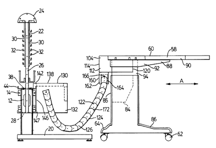
Figures 1 to 3 illustrate the major components that in combination
provide a work station system 10 constructed in accordance with the invention.
This system includes an elongate support beam 12 which per se is of known
construction and is similar, for example, to that disclosed in applicant's
United
CA 02259716 1999-O1-20
-9-
States patent No. 4,838,177 and more recently in applicant's copending
Canadian application No. 2,207,344 filed June 9, 1997. The beam 12 can
actually comprise a number of beam sections of standard length that can be
connected end-to-end by means of end flanges 14 and bolts. The beam is
supported by rigid, vertically extending supporting members or legs 16 a
substantial distance above the floor, ie. about nine inches. The legs are
connected to the beam for mounting same in a horizontal position above floor,
indicated for instance at 18 in Figures 9 to I I . The legs are supported in
an
upright position by adjustable feet 20 that can extend in just one direction
as
shown in Figures 1 to 3 or in opposite directions from their respective legs.
It
will be understood that the top end of each leg fits into a suitable opening
formed in the bottom of the adjacent beam section and the top end of the leg
can be secured in the beam by means of suitable bolts and nuts. The top of the
beam 12 is preferably no more than two feet above the floor and in a
particularly preferred embodiment the top is only about 18 inches from the
floor.
Extending upwardly from the beam is a primary support wall 22, also
shown and described in applicant's co-pending Canadian application No.
2,207,344. This wall is in a generally vertical position and can be provided
with
a rounded, decorative cap 24, if desired. The wall is solely supported by the
beam 12 and each section of the wall is rigidly connected to the beam by means
of vertically extending support columns or posts 26 which extend through
openings formed in the top of the beam. The bottom ends of the columns 26 fit
in slots or openings formed in a bottom plate 28 of the beam (see Figure 3).
Extruded metal panels 30 of known construction are secured to opposite sides
of the columns 26. Due to the rigidity of the columns 26 and the metal panels
and the secure manner in which the columns are mounted, the support wall 22
and any similarly constructed extension of this wall is quite strong and rigid
CA 02259716 1999-O1-20
-10-
and can support shelving, support brackets and items of considerable weight,
such as electrical equipment, mounted thereon. It should be noted that the
electrical and computer equipment typically mounted on the beam and on the
support wall is usually quite delicate and therefore unnecessary movement of
this equipment is to be avoided whenever possible. Preferably therefore the
position of this equipment should be fixed as it will be when mounted on the
rigid beam or the support wall. The metal panels 30 can be made of extruded
aluminum or aluminum alloy and each panel member is provided with a
number of horizontal connecting rails 32. These rails can extend the entire
length of each section of the wall and are preferably L-shaped in cross-
section
with an upwardly extending leg spaced from the outer or front surface of the
panel member. The bottom edge of the lowermost panel member can be spaced
some distance from the top of this support beam as shown, thereby leaving a
relatively open space 34 between the top of the beam and the panel members
for the passage of wires and cables. Of course, the support wall itself can be
used to pass or conduct wiring and cables horizontally or vertically, if
required.
Returning to the support beam 12, some features of this beam include
the provision of upper access openings formed in a top plate 38 of the beam.
Wires and cables can be inserted through or brought out through these
openings, if desired. Similar rectangular, access openings 40 and 42 can also
be
provided in the bottom and two vertical sides of the beam as shown in Figures
3
and 4. Extending upwardly from opposite sides of the beam are strong, rigid
connecting flanges 44 which can be provided with a series of bolt holes 46.
Similar, upwardly extending L-shaped flanges 48 can also be provided along
the bottom of the beam at each side, if desired.
An optional but preferred feature of this work station system is the
provision of open meshed raceways 50 on both sides of the posts 26, these
being attached by bolts to the posts and also to end columns 52 of the support
CA 02259716 1999-O1-20
wall. These raceways can be used to carry low voltage cable while high voltage
cable which comes up through the floor and through the bottom of the beam is
fed along the center of the hollow support beam 12.
It will be appreciated that the described work station structure including
the support beam, the legs for supporting the beam above the floor, and the
support wall form a rigid, horizontally extending supporting arrangement or
spine suitable for at least one station and preferably for a number of work
stations arranged on a floor area. This supporting arrangement can be laid out
and constructed in a number of ways, depending upon the particular
requirements for an office work site and it will be appreciated that this
supporting arrangement is highly adaptable to the particular needs of a user.
As
indicated, it is also known in the office furniture art to make a similar
rigid
supporting arrangement or spine without the use of an elevated support beam.
In these known systems, there is simply a supporting wall that extends up from
the floor, that accommodates wiring and cables in its interior and that
permits
heavy electrical equipment to be mounted thereon. It will be understood that
the
present invention in its broadest aspects includes the use of supporting walls
of
this type.
The work station system 10 also includes at least one movable desk unit
58 as shown in Figures 1 to 3. Each desk unit 58 has a work surface 60 thereon
and rollable members 62 mounted at a bottom end thereof and rollably
supporting the desk unit near the supporting arrangement, including the beam
12. The rollable members preferably comprise either small wheels or casters
and can be of known construction. Although four wheels are shown in the
drawings, it is also possible to construct the desk unit with, for example,
only
two rollable members or wheels 62, these being located at the front end 64 of
the base structure. If only two wheels at the front end are used, the rear end
of
the desk can simply be lifted by the user in order to move the desk unit
CA 02259716 1999-O1-20
-12-
inwardly or outwardly. The wheels or rollers are mounted on a suitable
supporting base 68 shown in Figures 1 to 3. It is also possible to use a
movable
desk unit which has no wheels or casters, particularly if the floor is a hard,
smooth surface and the desk unit itself is relatively light in weight. Such a
light
desk can be pushed back or forward as required, particularly if nothing heavy
is
resting on the desk.
The base section 68 has two vertical end panels 82, 83 which are joined
together by a horizontal connecting panel 84 and a vertical back panel 85.
Also
connecting the two end panels 82, 83 are two vertically extending forward
panels 93 and 96. Connected to the bottom of each panel 82, 83 or integrally
formed thereon are horizontally extending foot sections 86 on which the wheels
62 are mounted. Slidably connected to the top of the panels 82, 83, is a desk
top
section 88 which provides the aforementioned work surface. The top section
includes a generally flat, horizontal panel 90 to the bottom of which is
connected two connecting brackets 92 which can be made of a metal such as
steel. Extending downwardly from each bracket 92 is a vertical upper
connecting panel 94 that extends into a slot formed in the top of its
respective
end panel 82 or 83. Any suitable known connecting means can be used to
secure the desk top section 88 at the desired height once it has been moved to
this height. Again, for example, nuts and bolts can be passed through suitable
holes (not shown) in the end panels 82, 83 and the connecting panels 94 to
prevent movement of these panels relative to one another. Although an
adjustable desk unit is preferred, the present invention can also include the
use
of desk units having no adjustment capability, for example, no height
adjustment.
The work surface of the desk unit can support the usual files, writing
utensils and other office equipment normally placed on an office desk. In
particular, the desk unit can have a computer key board 100 mounted or placed
CA 02259716 1999-O1-20
-13-
thereon, usually centrally on the desk top. An electrical cord 102 typically
extends from this key board to a computer or central processing unit which can
be mounted off the desk unit itself as described hereinafter.
The desk unit 58 is provided with an elongate cable and wire housing
104 that extends along the rear side of the desk unit, that is the side
adjacent the
support wall 22. This housing is hollow and one or more access openings 118
can be formed in a bottom 116 thereof as shown in Figure 3. As shown the
bottom 116 is located a substantial distance above the floor, for example, 2.0
to
2.5 feet assuming that the desk unit is in the normal position for sitting.
The
housing can be fitted with a movable top (not shown) in order to cover the
wires and equipment therein. The size of this top will depend upon the
particular requirements of the desk unit. For example, installed in the
housing
may be a standard phone equipment module such as the module 106 illustrated
schematically in Figures 9 to 11. There may also, for example, be fitted into
this chamber a calculator module or perhaps a small video display screen. Any
area of the housing that is not filled with an equipment module such as these
can be covered with a movable top panel in order to provide more desk area
and in order to provide a very clean, finished appearance. Although one
specific
desk unit 58 has been illustrated, it will be appreciated that a variety of
mobile
desk units can be used with the present invention, the selected desk unit
being
designed to suit the specific project and equipment requirements.
The housing 104 projects rearwardly from the rear of the desk top as
shown in Figures 2 and 3. This housing has two vertical end walls 112 and a
rectangular rear wall 114. The housing has a front wall indicated at 120 in
Figure 2.
In addition to the rigid, horizontally extending supporting arrangement
and the movable desk unit or units, the work station system 10 also includes a
flexible cable and wire carrier device indicated generally at 122, this device
CA 02259716 1999-O1-20
-14-
extending between the support beam 12 and the movable desk unit 58 and
connected to both, preferably at connection points well above the floor. The
carrier device includes an elongate carrier section 124 comprising a plurality
of
interconnected links 126 that are pivotable with respect to each other,
preferably in a single, vertically extending plane as shown in the drawings.
The
carrier device 124 permits the desk unit 58 to move in a primary direction
indicated by arrow A in Figures 2 and 3 towards and away from the support
beam 12 and at the same time substantially prevents movement of the desk unit
in a horizontal direction perpendicular to this primary direction. The
preferred
carrier device serves several functions in addition to the basic purpose of
conducting wires and/or cables from the support beam to the desk unit. It
serves
as a wire and cable organizer to prevent loose and/or separate cables and
wires
extending between the beam and the desk. It provides protection for the wire
and cables that extend through it and reduces cable fatigue. Furthermore,
because the amount of pivotal movement is generally limited, it can prevent
the
cable from being bent unduly or improperly when this is required to avoid
damage to the cable.
The carrier device 122 illustrated in Figures 1 to 3 includes a connecting
module 130 attached to the beam end of the flexible carrier section 124. As
indicated by the dashed lines in Figures 2 and as shown more clearly in Figure
4, an end section of the carrier section 124 is located within the module 130.
The preferred illustrated module includes two opposite side walls 132, 134,
each with a vertically extending edge 136 adapted to rest against a vertical
side
of the support beam 12 and a top wall 138 which optionally may be provided
with an access opening, if desired. This preferred module also has two hook
members 142 which can be an integral extension of each of the side walls and
which are located at a top corner of the side walls. The hook members
detachably engage the support beam and, in particular, one of the upwardly
CA 02259716 1999-O1-20
-15-
extending connecting flanges 44.To provide a very rigid and strong connection
between the connecting module and the beam, the bottom corner 147 of each
side wall 132, 134 is also preferably connected by means of bolts and nuts and
suitable connecting brackets to the bottom of the edge of the beam.
Incidentally, in a known manner, the adjacent side wall of the beam 12 can
optionally be covered with a cover plate 144 in those regions of the beam
where
the access openings in the side of the beam are not in use. Figure 4 shows the
use of this cover plate to the left of the module 130 and shows the beam side
without the cover plate on the right side of the module. For present purposes,
this cover plate can be considered part of the support beam 12. If there is a
cover plate, this plate would normally, but not necessarily, end approximately
at the aforementioned vertical edge 136 of the module. Often the wires and
cables exit the support beam through the top of the beam and not the side. In
such cases, the cables can enter the module 130 from above.
The illustrated preferred module has a substantially open bottom through
which the flexible carrier section 124 can extend and a substantially open end
indicated at 146 (see Figures 2 and 3). This open end 146 is the end adjacent
the support beam 12. The open bottom of the module allows the desk unit
attached to the carrier section to move closer to the beam. In order to
strengthen the rigidity of the module and to partially close the visible end
thereof, the module preferably has a vertical front wall 148 which, as
illustrated, is perforated and which extends only partway down the edge of the
sidewalls 132, 134 leaving a frontal opening 150 through which the carrier
section 124 can also extend, particularly when this section is stretched out
by
moving the desk unit outwardly away from the beam. The beam end of the
carrier section 124 is pivotably connected to the module 130 by means of two
strong pivot pins or bolts 152, one of which is shown in Figure 4. A preferred
form of bolt 152 is a shoulder bolt to provide the end section a degree of
CA 02259716 1999-O1-20
-16-
movement. The preferred pivot axis provided by the bolts 152 is a substantial
distance above the floor. In the illustrated preferred embodiment, it is
located at
about the same level as the top of the beam, that is, about 18 inches above
the
floor. The elevated connection point helps to ensure that the carrier section,
which preferably ranges between 36 inches and 60 inches in length has the
required degree of slack so that the desk unit can be moved as required. It
will
be appreciated that the interior width of the module 130 is just slightly more
than the width of the links 126 that together make up the carrier section. The
construction of the carrier section, a preferred embodiment of which is
described in more detail below, together with the restraint on the bending or
twisting of this section imposed by the sides of the carrier module 130 helps
to
restrain the movement of the desk unit 56 or 58 so that it moves primarily in
the
direction indicated by the arrow A in Figures 2 and 3, that is, either
directly
towards or away from the support beam 12. The construction of the module 130
and the carrier section 124 helps to substantially prevent movement of the
desk
unit in a direction perpendicular to the primary direction, that is, it helps
prevent movement of the desk unit in the direction indicated by the arrows B
in
Figure 4.
As indicated, the support beam 12 has access openings 42 formed in one
or both of the vertical, longitudinal sides thereof. The carrier device 122 is
connected to the support beam 12 in the region of one of these access openings
42 whereby wires or cables extending along the interior passageway formed by
the support beam are able to pass through the adjacent access opening and the
elongate carrier section and out to the desk unit. Note also that the carrier
device 122 and in particular the beam end of the carrier section are mounted a
substantial distance above the floor. Preferably the pivot pin connection for
the
beam end of the carrier section is at least one foot and more preferably at
least
1.5 feet above the floor level. This connection arrangement helps to provide
the
CA 02259716 1999-O1-20
-17-
carrier section with the required degree of movement (slack) to permit the
desk
unit to move horizontally or vertically as desired.
Turning to the desk end of the carrier device 122, this end is preferably
firmly connected to the cable and wire housing mounted along the rear of the
desk top already described above. In the preferred embodiment, the desk end of
the carrier section is pivotably connected to a channel shaped connector 160
that extends downwardly from the aforementioned housing but is a substantial
distance above floor level (ie. about 2.0 feet). In the illustrated
embodiment,
this connector 160 is located in the center of the bottom 116 and is open at
the
rear. The connector has two vertical side walls 162 and a front wall 164
extending between these side walls. The connector is preferably made from
sheet metal that has been bent to the required shape and size. It will be
understood that an access opening into the cable and wiring housing is
provided
directly above the channel shaped connector 160 so that wires and cables
passing through the carrier device can readily pass into the housing. The desk
end of the carrier section 124 is connected by mean of one or two strong pivot
pins or bolts 166 to the side walls 162. Again, the internal width of the
connector 160 is just slightly greater than the width of the links that make
up
the carrier section 124 and thus the side walls 162 act to guide the pivoting
movement of the end links and help to prevent twisting of the carrier section
as
the desk unit is moved. Again, because of the height of the pivot axis
provided
by the bolts 166 and the end of the carrier section attached thereto, the
carrier
section is provided with the required slack to permit the desk unit to move as
required. The carrier device is preferably constructed and mounted to not
restrict movement of the mobile desk unit towards the support beam and
support wall. In one preferred embodiment, this pivot axis is about 29 - 30
inches above the floor with the desk top in the normal position for sitting.
The
preferred range for the height of this pivot axis above the floor is between 2
and
CA 02259716 1999-O1-20
-18-
2.5 feet. The preferred work station system of the invention is constructed so
that the carrier section 124 stays off the floor. This can be accomplished by
controlling the length of the carrier section and the height at which its ends
are
mounted.
The preferred construction of the links which make up the carrier section
124 is illustrated in Figures 1, 4 and 8. The preferred links 126 are
generally
uniform in their construction. The links can be constructed in the same manner
as the links of the cable carrier sold under the trademark "GORTRAC
NYLATUBE". Each link is formed with a semi-circular end section 172 on
two opposite sides thereof. This end section fits into a cooperating semi-
circular
recess 174 formed in the adjacent end of the next link. One suitable form of
cable carrier is described in detail in United States patent No. 4,658,577 of
A &
A Manufacturine Co., Inc. Briefly, each link has a generally rectangular
transverse cross-section and has a hollow interior through which cables and
wires can readily pass. The sections are pivotable with respect to each other
a
limited amount to form a flexible tube that is able to bend in a single plane.
The
cable or conductors are fully enclosed while being supported by the cable
carrier. Each link can be molded from a single piece of suitable plastic
material
which should be sufficiently strong to withstand normal stress forces applied
to
it by the movable desk unit. If desired, the links can be made with a dividing
wall in order to form two separate passageways, for example, one for high
voltage cable and the other for low voltage wiring.
Extending forwardly from the arcuate recess 174 on each side of the link
is a coupling member 176 outlined in dashed lines in Figure 8. The outer
surface of each coupling member is provided with a recess which is configured
to receive a complimentary boss formed on the inner wall of the adjacent link.
These bosses can pivot within their respective recesses. Each plastic end link
180 can be secured in a suitable connecting bracket 182 on which the pivot
pins
CA 02259716 1999-O1-20
-19-
or bolts can be securely mounted. It is these pivot bolts 152 which pivotably
connect the carrier section to the module 130.
Turning now to the illustrations of Figures 6, 7 and 9 to 1 l, Figures 6
and 7 shown how a work station system constructed in accordance with the
invention can be used both in a sitting position (Figure 6) and in a standing
position. In the sitting position, the top section of the desk unit 58 has
been
lowered. In this position the sitting user 60 of the system can readily type
on a
keyboard located on the work surface of the desk. The user is also able to
observe two liquid crystal display units or screens 200. These units 200,
which
are quite heavy for their size, are mounted on and supported by a side of the
support wall 22. Liquid crystal display units of this type are of known
construction and therefore a detailed description thereof in the present
application is deemed unnecessary. A suitable pivoting support bracket 202 or
204 can be used to connect the display unit to the metal side panel of the
support wall and, in particular, to the connecting flanges formed thereon. The
upper display unit 200 as shown in Figure 6 is directly in front of the user's
head along a generally horizontal sight line. The lower display unit 200 is
tilted
at an angle to the vertical in order that its display screen can be readily
seen as
well by the same user 60.
Turning to Figure 7, the desk unit 58 is shown in an elevated position
suitable for a user 60 who is standing up. It will be seen that the user
standing
in front of the desk unit is still able to see quite readily both of the
liquid crystal
display units 200. Note that the top section of the desk unit 50 can be raised
quickly and easily to the position shown in Figure 7 since the wires and
cables
that extend through the carrier device 122 do not need to be disconnected and
then reconnected again after the top section has been raised. It is also very
easy
for the user to move the desk unit inwardly or outwardly relative to the
support
beam and the support wall because of the highly flexible connection that
exists
CA 02259716 1999-O1-20
-20-
between the two components.
Turning now to the arrangements illustrated in Figures 9 to 11 wherein
the user 60 is seated, these drawings illustrate various forms of display
units or
display devices that can be mounted on the support wall and further show how
a computer or central processing unit can be mounted on or adjacent to the
support beam and away from the movable desk. In the work station shown in
Figure 9 there are again two liquid crystal display units 200 mounted one
above
the other. Directly below the bottom display unit and mounted to the side of
the
support beam 12 is a horizontally extending central processing unit 206
outlined in dashed lines. This computer can be of standard, well known
construction and accordingly a further description thereof is deemed
unnecessary. The computer can be housed in a suitable computer housing 208
which can also be of known construction and which has connectors on its beam
side for rigidly connecting the housing to a vertical side of the support
beam. In
this case the housing 208 would be mounted either to the left or to the right
of
the connecting module 130 for the carrier device 122. It is also possible to
mount the connecting module 130 on the support wall 22 above the housing
208. Because the CPU and the display screens are mounted on the support
structure which is separate from the desk unit, the desk unit itself is not
required to bear or support relatively heavy loads and this helps to enhance
the
mobility of the desk unit as well as making more desk space available. The
display screens will normally be electrically connected to and operated by the
CPU 206.
Referring to Figure 10, this illustration shows a single liquid crystal
display unit 210 pivotably mounted on the support wall 22 at a location which
is readily visible from a seating position at the front of the desk unit.
Mounted
next to and on the support beam is a vertically extending computer or CPU 212
which can be a standard "tower type" computer. The CPU extends parallel to
CA 02259716 1999-O1-20
-21-
the vertical side of the support beam and to the support wall and is mounted
on
the beam by suitable known brackets or by means of a support housing attached
to the side of the beam. Again, the computer can be positioned either to the
left
or to the right of the connecting module 130 for the carrier device or, if the
module is mounted on the support wall, the computer can be located below this
module. Although it is possible to have the computer simply sit on the office
floor in approximately the position shown in the drawing, it can be mounted on
the side of the support beam using suitable brackets.
The arrangement illustrated in Figure 11 is similar to that shown in
Figure 6 except that instead of liquid crystal display screens, a single
television
monitor, or computer monitor (also known as a CRT), indicated at 214 is
mounted at about desk top height on the support wall 22. The monitor can rest
on a horizontal shelf connected to the support wall by two supporting brackets
216. As the construction of these supporting brackets and the support shelf is
known in the modular office furniture art, a detailed description thereof is
deemed unnecessary herein. It will be recognized that the video monitor 214
has a significant weight and some work stations may be provided with two or
more of these monitors. Thus, by removing this weight from the desk unit and
having these monitors supported by the separate support wall, the desk unit
remains easily movable by a user and can be readily raised or lowered.
Turning to Figure 5, this plan view shows how two movable desk units
220 can be arranged in a substantially side-by-side manner. These desk units
are similar in their construction (for present purposes) as the desk unit 58
shown in Figures 1 to 3. The two units are arranged on one side of a long
support beam 12 (shown only schematically) which comprises a number of
support beam sections 222 of uniform length, for example, four feet. Mounted
on the support wall above the support beam are a number of LCD display units
200. As illustrated, there are three of these LCD units for each of the two
desk
CA 02259716 1999-O1-20
-22-
units 220 with one LCD display mounted directly in front of each user, another
unit mounted to the left and a third unit mounted to the right. Also
illustrated
schematically in Figure 5 is the carrier device 122 that connects each desk
unit
220 to the support beam 12. Figure 5 illustrates how the preferred carrier
device
122 is able to guide the movement of each desk unit in the primary direction
(indicated by the arrows X) towards and away from the support beam. Because
the carrier device will only pivot in a single vertical plane, the device 122
substantially prevents movement of each desk unit 220 in a horizontal
direction
indicated by the arrow Y, this direction being perpendicular to the primary
direction of movement. It will thus be seen that this guidance provided by the
carrier device helps to prevent one desk unit from colliding with another desk
unit or interfering with the back and forth movement of the adjacent desk
unit.
It is also possible in some versions of the invention to use a carrier device
that
can pivot in a full 360 degree circle of movement at least to a limited
extent.
Such carrier devices are already known in the cable carrier art and therefore
a
description thereof is deemed unnecessary herein. One such cable carrier is
taught in U.S. Patent 5,824,957 issued October 20, 1998. Another carrier guide
with two-directional joints is taught in earlier U.S. patent 4,840,023 issued
June
20, 1989. With the use of these mufti-directional carrier devices, the desk
units
connected thereto can move in more than one horizontal direction including
sideways. This may not be a problem if the desk unit is spaced a good distance
from other desk units. In the alternative, other means could be provided for
guiding the movement of the desk unit such as guide tracks on the floor or
guiding surfaces arranged beside the desk unit (i.e. an adjacent desk, table
or
desks that are fixed in their own position).
It will be appreciated by those skilled in this art that various
modifications and changes can be made to the described work stations and
systems without departing from the spirit and scope of this invention. For
CA 02259716 1999-O1-20
-23-
example, instead of using a rigid support wall on top of the support beam as
shown, it is also possible to provide simply a divider wall that extends
vertically above the beam. This wall may have cloth covered sides, for
example, and be provided simply for privacy purposes and/or acoustical
reasons. The use of such a wall may be possible if it is not necessary to
mount
relatively heavy equipment such as monitors, etc. on the wall. Accordingly,
all
such modifications and changes as fall within the scope of the appended claims
are intended to be part of this invention.
15
25