Note: Descriptions are shown in the official language in which they were submitted.
CA 02259992 1999-O1-11
WO 98/02079 PCT/SE97/01252
ELECTRIC TOILET
TECHNICAL FIELD
The present invention relates to an electric toilet comprising a cabinet or
housing, an
opening in the cabinet's top side, a lid assigned to the opening, a bowl
arranged inside
the opening, which bowl is operable downwards, a combustion chamber arranged
under
the upper bowl and provided with an opening directed upwards, arranged to
which
opening is a lid, heating coils arranged in the combustion chamber and an
evacuation
device connected to the combustion chamber.
BACKGROUND TO THE INVENTION
The most common form of toilets without a doubt are water toilets. For reasons
which
are self evident, these cannot be used for certain application areas and in
certain places,
for example holiday cottages and boats. Other types of toilets have been
developed for
these, such as earth closets, freezer toilets and electric toilets, for
example. Recently
these types of toilets have also come into fashion on account of environmental
aspects.
Many places and urban districts do not permit water toilets to be connected up
to the
sewerage system on account of treatment plant capacity and groundwater
resources. Of
the alternative toilets, electric toilets offer the absolute minimum of waste
products.
Electric toilets function so that they are arranged with a receptacle under a
protective lid,
into which receptacle a liquid-resistant paper bag is placed. When one has
relieved
oneself into this and 'lushes", i.e. activates the device by stepping on a
pedal, for
example, the receptacle is opened and the waste drops down into a combustion
chamber
placed under the receptacle. When the pedal is then released, the receptacle
and a lid for
the combustion chamber are closed. Heating coils are then activated in the
combustion
chamber, which bums the waste. An evacuation facility from the combustion
chamber
arranged with a fan sucks out the combustion gases and routes them out into a
ventilation pipe. Following combustion, only a little ash remains in the
bottom of the
combustion chamber.
CA 02259992 1999-O1-11
PCT/SE97/01252
WO 98/02079 2
The electric toilets which are on the market have a number of disadvantages.
Due to the
fact that the combustion chamber is designed as a vertical cylinder and the
electric coils
are arranged in the top edge of the cylinder up by the lid, the coils do not
provide
uniform radiant heat in the bottom of the combustion chamber, but "pockets"
are
obtained with poorer heat, especially around the edges between the bottom and
the side.
Other disadvantages are that the top part of the bag has a tendency to get
caught
between the lid and the edge of the combustion chamber, in which case the bag
does not
collapse when it drops down but stands up. Tbis also applies if the foot slips
off the
pedal during 'flushing". If combustion is then commenced, the combustion
chamber is
not closed, but flames may emerge between the lid and the opening.
Another serious disadvantage is the design of the evacuation device. If the
power for the
electric toilet is lost while combustion is in progress, the power for the
suction fan is also
lost. This means that the flue gases from the hot faeces are no longer sucked
out but end
up in the space where the toilet is located, with a powerful stench as a
result.
Furthermore, a nasty-smelling coating is obtained on the fan, especially when
this is
arranged in the path of the flue gases.
From the safety aspect, the electric toilets on the market are not optimum, as
they permit
flushing to occur when the protective lid is raised. This causes children for
example
possibly to get the idea into their head of stepping on the pedal with the
protective lid
open, in the event of which the receptacle and the combustion chamber are
opened, with
a major risk of burns. In addition, these electric toilets are disposed with a
spring system
for suspension of the upper and lower part of the combustion chamber, which
springs
lose their elasticity with time on account of the heat and even break, which
on the one
hand causes a gap between the parts of the combustion chamber and on the other
means
that the toilet cannot be used.
A fiuther disadvantage is that the electric toilets on the market do not have
any spillage
protection in case a person does not know how the toilet is to be used and
urinates in the
receptacle without having first placed a bag therein. The urine then runs down
through
the receptacle and into the interior of the toilet with major cleaning
problems as a result.
CA 02259992 1999-O1-11
WO 98/02079 '1 PCT/SE97/01252
Further disadvantages are that the locking of the ash box, i. e. the lower
part of the
combustion chamber, includes springs which draw this up towards the upper part
of the
combustion chamber. These lose their elasticity after a relatively short time,
largely due
to the heat from the combustion, at which a gap is created between the ash box
and the
upper part with a strong odour as a result.
DESCRIPTION OF THE INVENTION
The object of the device according to the invention is to remedy the above
problem
complex and disadvantages of conventional electric toilets. This is achieved
according to
an aspect of the invention by an electric toilet characterised in that the
combustion space
of the combustion chamber is shaped principally spherically and that the
heating coils are
arranged in the upper part of the combustion space around its circumference.
According to an aspect of the invention, it is characterised in that the
bottom of the
combustion space is arranged with a turning device directed upwards.
According to another aspect of the invention, it is characterised in that the
evacuation
device is arranged with a fan and that the fan is driven by low direct-current
voltage.
The electric toilet according to the invention displays a number of advantages
compared
with conventional electric toilets. Thanks to the fact that the combustion
space is shaped
principally spherically and that the heating coils are arranged in the upper
part of the
combustion space, directed heat radiation down towards the bottom of the
combustion
space is obtained, whereby uniform heat distribution is obtained without
cooler
'dockets". The heating coils are preferably arranged outside the area of the
opening,
whereby the waste is prevented from falling down onto the heating coils during
flushing.
The turning device in the bottom of the combustion space ensures that the
falling bag is
turned out and in and the waste is dispersed in the combustion chamber, which
allows a
shorter combustion time.
CA 02259992 1999-O1-11
WO 98/02079 4 PCT/SE97I01252
Due to the fact that opening/closing of the toilet takes place by means of
motors, there is
no risk of the combustion space closing up insufficiently, which can occur
with pedal
manoeuvnng.
These and other aspects of and advantages of the invention will be clear from
a detailed
description of a preferred embodiment and the subsequent patent claims.
BRIEF DESCRIPTION OF DRAWINGS
In the following description of a preferred embodiment, reference will be made
to the
enclosed drawings, of which
Fig. 1 shows a lateral view in section of an embodiment of an electric toilet
according to
the invention,
Fig. 2 shows a lateral view of an upper bowl forming part of the device
according to
Fig. 1,
Fig. 3 shows the upper bowl according to Fig. 2 rotated by 90° and
Fig. 4 shows a view from above of a bottom plate forming part of the device
according
to Fig. 1.
DESCRIPTION OF PREFERRED EMBODIMENT
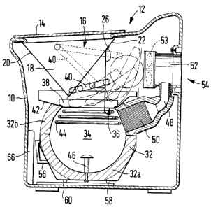
The device which is shown in the drawings comprises a cabinet or housing 10 of
suitably
heat-resistant and thermally insulating material. The cabinet is of a height
which makes it
comfortable to sit on. On the top side 12 of the cabinet and in the front edge
a lid 14 is
arranged articulately in its rear edge. Arranged under the lid 14 is an
opening 16, the
edge of which is gently rounded. Down in the opening a bowl 18, referred to
henceforth
as the upper bowl, is affixed to the inside at the edges of the opening. The
upper bowl
18 is formed with inwardly sloping front and back walls 20, 22, which meet
along a line,
and inwardly sloping side walls 24 so that the upper bowl has the appearance
of a coffee
filter funnel, Fig. 2 and 3. The back wall 22 is arranged with a part 26 which
is hinged
CA 02259992 1999-O1-11
WO 98/02079 ~ PCT/SE97/01252
rotatably around a bracket 28 a little way up on the back wall. The hinged
part is also
arranged with side walls 30 with the same inclination as the upper bowl's side
walls.
Arranged under the upper bowl 18 is a combustion chamber 32. The combustion
space
34 of the combustion chamber 32 has a principally spherical shape with a
principally
circular opening 36 towards the top. The combustion chamber 32 is located in
relation
to the upper bowl 18 so that the lower end of the upper bowl's front wall 20
is arranged
above and by the front edge of the opening 36. The opening of the combustion
chamber
is provided with a lid 38 which closes the combustion chamber's combustion
space by
means of a sealing ring. A hinge arrangement 40 is a$Iaced both to the hinged
part 26 of
the upper bowl 18 and to the lid 38 of the combustion chamber, which hinge
arrangement 40 is actuated preferably by an electric motor (not shown).
Arranged on the combustion chamber 32 and around its opening 36 is a spillage
guard 42
in the form of a trough with lateral edges. In the upper part of the
combustion space,
heating coils 44 are arranged in a spiral round the periphery of the
combustion space
inside an area with the form of a spherical zone. Due to this design, the heat
radiation is
directed downwards towards the centre of the combustion space. The combustion
space
34 is also arranged with a turning device 46 in the form of a spike with an
upwardly
rounded disc on its top in the centre of the chamber's bottom An evacuation
pipe 48 is
assigned to the combustion chamber. Affxed in the pipe nearest to the
combustion
space 34 is a catalyzer 50. The pipe 48 then continues to a suction fan 52 and
on to au
outlet 54 in the back of the cabinet. The outlet is then connected to a
suitable ventilation
pipe (not shown). The combustion chamber 32 is divided into a lower and an
upper part,
32a and 32b respectively. The underside of the lower pan 32a is provided on
the one
hand with a handle 56 in its front part and on the other hand with feet or
beads 58, three
in the embodiment shown. Arranged on the inside of the cabinet's bottom is a
base plate
60 of a certain thickness. Arranged in the base plate are three grooves 62,
Fig. 4, and
ramps 64 from the grooves to the top side of the base plate. Arranged on the
front side
of the cabinet in its lower part is a door 66.
The device functions as follows. When the toilet lias to be used, the
protective lid 14 is
CA 02259992 1999-O1-11
WO 98102079 6 PCT/SE97/01252
raised. A bag of liquid-resistant paper with the same shape as the upper bowl
18 is
placed into this. When one has relieved oneself, the protective lid 14 is
closed. This
activates the electric motor, which operates the rear part 26 in the upper
bowl and the lid
38 of the combustion chamber 32 so that these open and swing out of the way
respectively. The bag then drops down into the combustion space 34 and ends up
on the
turning device 46 in its bottom, whereupon the bag is turned out and in and
the waste is
dispersed in the combustion chamber. The rear part 26 and the lid 38 of the
combustion
chamber 32 are closed, at which the heating coils 44 are activated. The fan 52
for
evacuation is activated. Under the influence of the heat from the heating
coils 44, the
faeces are now burnt, vaporized and/or gasified and the flue gases are
conveyed up
through the catalyzes 50, where they are purified of unpleasant odours. The
flue gases
are then conveyed into the fan 52. This takes its supply air from the inside
of the cabinet
and ensures air circulation therein. The fan rotor 53 which is arranged
between the
supply air intake in the fan housing and the flue gas inlet blows the flue
gases out into the
ventilation pipe. Due to this design, the flue gases do not pass through the
fan rotor or
coat this. Thanks to the design of the combustion chamber and its heating
coils 44, heat
radiation is obtained down towards the faeces and no "pockets" are obtained
where the
heat radiation reaches poorly.
When the toilet is to be emptied of ash, the door 66 in the front edge of the
cabinet is
opened. The handle 56 is then grasped and the whole ofthe lower part 32a of
the
combustion chamber turned, whereupon the feet 58 slide on the base plate 60
and down
along the ramps 64 into the grooves 62. The under-part can then be pulled
right out and
emptied. Due to this design, a simple and functional solution is obtained for
dividing and
attaching the two halves of the combustion chamber without springs and similar
arrangements.
The fan is preferably driven by a 12V motor and the device is equipped with a
back-up
battery (not shown). This is for cases in which the power disappears before
combustion
is completely finished in the combustion chamber. It is then ensured that the
fa~i
continues to function and let out the odours from the hot waste, at least
until it cools
down.
CA 02259992 1999-O1-11
WO 98/02079
PCT/SE9?/01252
The spillage guard 42 is arranged for those cases when a user urinates into
the device
without having placed any paper receptacle in the upper bowl. The urine then
runs down
from the upper bowl 18 to the spillage guard 42 and when the protective lid is
closed the
lid 38 for the combustion chamber is opened and the urine runs down into it.
Compared
with conventional electric toilets without spillage guards, it is considerably
easier to clean
the spillage guard of any urine remaining than the urine which in conventional
toilets is
allowed to run down everywhere in the interior of the toilet, with major
cleaning
problems as a result.
The combustion chamber can also be disposed with a pipe inlet. This is
connected via
pipes to a urinal arranged close to the device. When one has relieved oneself
in the
urinal, the liquid runs down into the combustion chamber and the urinal is
rinsed using a
smaller quantity of water to remove the odour, which water also runs down into
the
combustion chamber which burns/gasifies the liquid. With this addition a paper
receptacle does not need to be placed into the upper bowl on urinating.
With an electric toilet according to the invention, a toilet is obtained which
is
considerably more functional than previous electric toilets and in which the
disadvantages
these exhibit are removed.
It must be understood that the invention is not restricted to the embodiment
described
above and shown in the drawings, but can be modified within the scope of the
following
patent claims.