Language selection

Search

Patent 2260547 Summary

Third-party information liability

Some of the information on this Web page has been provided by external sources. The Government of Canada is not responsible for the accuracy, reliability or currency of the information supplied by external sources. Users wishing to rely upon this information should consult directly with the source of the information. Content provided by external sources is not subject to official languages, privacy and accessibility requirements.

Claims and Abstract availability

Any discrepancies in the text and image of the Claims and Abstract are due to differing posting times. Text of the Claims and Abstract are posted:

  • At the time the application is open to public inspection;
  • At the time of issue of the patent (grant).
(12) Patent Application: (11) CA 2260547
(54) English Title: A PERCUSSIVE DOWN-THE-HOLE HAMMER AND A DRILL BIT
(54) French Title: MARTEAU FOND DE TROU A PERCUSSION ET TREPAN
Status: Dead
Bibliographic Data
(51) International Patent Classification (IPC):
  • E21B 4/14 (2006.01)
  • E21B 10/38 (2006.01)
  • E21B 21/10 (2006.01)
(72) Inventors :
  • ASBERG, BENGT (Sweden)
  • BECCU, RAINER (United States of America)
(73) Owners :
  • SANDVIK AB (Sweden)
(71) Applicants :
  • SANDVIK AB (Sweden)
(74) Agent: GOWLING LAFLEUR HENDERSON LLP
(74) Associate agent:
(45) Issued:
(22) Filed Date: 1999-02-01
(41) Open to Public Inspection: 1999-08-02
Examination requested: 2003-12-01
Availability of licence: N/A
(25) Language of filing: English

Patent Cooperation Treaty (PCT): No

(30) Application Priority Data:
Application No. Country/Territory Date
9800283-5 Sweden 1998-02-02

Abstracts

English Abstract


The present invention relates to a percussive down-the-hole hammer and a drill
bit. The drill bit (13) comprises a body having a front drilling face,
a central passageway (18) extending from a rear end (30) of the body in
direction towards the drilling face to conduct flushing medium to the drilling
face.
The rear end comprises an impact surface (24) surrounding the passageway
(18). The central passageway (18) is adapted to receive a foot valve (20) to
transfer pressurized air through the drill bit. The intersection of the drill
bit (13)
impact surface (24) and the drill bit passageway (18) is provided with a
circumferential projection (25) integrated with the drill bit (13) to deflect
jet
streams of water during drilling.


Claims

Note: Claims are shown in the official language in which they were submitted.


5
Claims
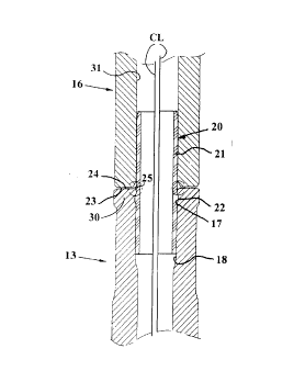
1. An air operated down-the-hole hammer (10) for rock drilling, comprising:
a generally cylindrical casing (11),
a drill chuck (12) mounted at one end of said casing to receive a drill bit
(13),
a drill sub (14) attached to the other end of said casing,
a foot valve (20) located in a central passageway (18) in a drill bit anvil
(30) and
projecting from an impact surface (24) of the anvil, said foot valve being
intermittently
enclosed by a central bore of a reciprocating piston (16) to transfer
pressurized air
through the drill bit,
characterized in that the intersection of the drill bit (13)/piston (16)
impact surface (24,23) and the drill bit/piston passageway (18,31) is provided
with a circumferential projection (25) integrated with the drill bit
(13)/piston (16)
to deflect jet streams of fluid during drilling.
2. The down-the-hole hammer according to claim 1,
characterized in that the circumferential projection (25) has a generally
conical cross-section formed by a radially internal entrance surface (26), a
curved top (27) and a radially external deflection surface (28), said
deflection
surface (28) forming an angle (a) with the center line (CL) of the drill bit
(13)/piston (16).
3. The down-the-hole hammer according to claim 2,
characterized in the angle (a) is acute, preferably at least 45°.
4. The down-the-hole hammer according to claim 1,
characterized in that the piston (16)/drill bit (13) is provided with a
chamfer (29) for intermittently housing the projection (25) during drilling.
5. A percussive drill bit comprising a body having: a front drilling face,
a central passageway (18) extending from a rear end (30) of the body in
direction towards the drilling face to conduct flushing medium to the drilling
face,


6


said rear end comprising an impact surface (24) surrounding the passageway
(18),
said central passageway (18) being adapted to receive a foot valve (20) to
transfer
pressurized air through the drill bit,
characterized in that the intersection of the drill bit (13) impact surface
(24) and the drill bit passageway (18) is provided with a circumferential
projection (25) integrated with the drill bit (13) to deflect jet streams of
water
during drilling.
6. The drill bit according to claim 5,
characterized in that the circumferential projection (25) has a generally
conical cross-section formed by a radially internal entrance surface (26), a
curved top (27) and a radially external deflection surface (28), said
deflection
surface (28) forming an angle (a) with the center line (CL) of the drill bit
(13).
7. The drill bit according to claim 5,
characterized in that the angle (a) is acute, preferably at least 45°.

Description

Note: Descriptions are shown in the official language in which they were submitted.


CA 02260547 1999-02-25
11310DE 1999-OI-21
A PERCUSSIVE DOWN-THE-HOLE HAMMER AND A DRILL BIT
Field of the invention
The present invention relates to a percussive down-the-hole hammer and a drill
bit according to the preambles of the appended independent claims.
Prior art
At drilling with down-the-hole hammers under ground, such as in tunnels the
dust generated by the drilling operation often is bound by the use of water
mixed
into the pressurized air driving the hammer and flushing the dust away. The
down-the-hole hammer used is provided with a plastic foot valve located in a
central passageway in a drill bit anvil and projecting from the impact surface
of
the anvil. The foot valve is repeatedly enclosed by a central bore of the
reciprocating piston to transfer spent pressurized driving air through the
drill bit.
When drilling downwardly, water is deposited on the impact surface between the
impacts such that each impact will create a jet stream of water away from the
impact surface. The part of the jet stream traveling radially inwardly will
cut into
the plastic foot valve and finally the valve will break such that the hammer
will
stop impacting.
Objects of the invention
An object of the present invention is to provide a drill bit for a down-the-
hole
hammer which provide for extended lifespan of the foot valve.
Another object of the present invention is to provide a drill bit for a down-
the-hole
hammer that will have a longer life between service than hitherto known
hammers.
These and other objects of the drill bit and the down-the-hole hammer
according
to the present invention will become apparent from the following detailed


CA 02260547 1999-02-25
1I310DE 1999-Ol-21 2
description of a preferred embodiment thereof in connection with the
accompanying drawings.
Description of the Drawings
Fig. 1 shows a down-the-hole hammer according to the present invention in a
longitudinal section. The left hand portion of Fig. 2 shows a foot valve and
portions of a drill bit according to the present invention and a piston, in a
longitudinal section, and the right hand part thereof discloses a prior art
solution.
Fig. 3 shows an enlarged view of the prior art portion of Fig. 2. Fig. 4 shows
an
enlarged view of the left hand portion of Fig. 2 and the drill bit according
to the
present invention.
Detailed Description of a Preferred Embodiment of the Invention
In Fig. 1 there is shown a preferred embodiment of a down-the-hole hammer 10
according to the present invention. The hammer 10 comprises an outer
cylindrical casing 11 connectable to a rotatable drill pipe string, not shown,
through which compressed air is conducted. A hammer piston 16 reciprocates in
the cylindrical casing 11, and compressed air is being directed alternately to
the
upper and lower ends of the piston to effect its reciprocation in the casing,
each
downward stroke inflicting an impact blow upon the anvil 30 of a drill bit 13
extending upwardly within the lower portion of the cylindrical casing. The
piston
comprises a passageway 31 for pressurized air. The percussive down-the-hole
hammer further comprises a top sub 14, a check valve 35, a control or fluid
feed
tube 15, a foot valve 20, a retaining means 33 and a driver sub 12. The down-
the-hole hammer 10 is of conventional design except for the shape of the anvil
of the drill bit 13. Usually the addition of water into the pressurized air
for
avoiding dust problems amounts to about 4 to 40 I of water per minute.
The foot valve 20 is of generally cylindrical basic shape and is made of
plastics,
30 such as nylon, see Fig. 2. The foot valve is a hollow tube 21 provided with
a
circumferential ridge 22 of a diameter larger than the diameter of the tube
21.
The ridge 22 is provided to keep the foot valve in the drill bit by pressing
the


CA 02260547 1999-02-25
11310DE 1999-OI-21
ridge into a corresponding circumferential groove 17 in a drill bit passageway
18.
The foot valve 20 extends generally equally far into the drill bit and the
piston 16
when the piston front surface 23 impacts on the drill bit rear surface 24. The
piston front surface 23 connects to a circumferential chamfer 29 located at
the
orifice of the passageway 31 of the piston.
Turning now to the prior art disclosure of Fig. 3. It is previously known to
chamfer
or smoothen the intersection of the drill bit rear surface 24 and the drill
bit
passageway 18. During drilling, the deposited water on the impact surface will
create a jet stream of water in a direction indicated by the arrow in Fig. 3.
The
part of the jet stream traveling radially inwardly has an angle of attack
about 90°
and will cut into the plastic foot valve and finally the valve will break.
When the
foot valve is broken there will not be any lower chamber present where
pressurized air can assemble to lift the piston but instead the air will be
transferred immediately through the drill bit passageway 18 and the hammer
will
not work.
Now looking at Fig. 4 there is presented a solution to the problem of jet
stream
damages to the foot valve. The intersection of the drill bit rear surface 24
and the
drill bit passageway 18 is provided with a jet stream deflector in the shape
of a
circumferential lip 25 integrated with the drill bit 13. The jet stream of
water
during drilling will be deflected by the lip 25 in a direction indicated by
the arrow
in Fig. 4 in such a manner that the energy of the stream is reduced to about
the
half. In addition, the attack angle of the stream will be obtuse such that
only
about half of remaining energy of the stream is transferred onto the foot
valve.
The lip 25 can be of many alternative shapes but in the preferred embodiment
the lip has a conical cross-section formed by a radially internal entrance
surface
26, a curved top 27 and a radially external deflection surface 28. The
deflection
surface 28 forms an angle a with the center line CL of the drill bit 13. The
angle
a is acute and is preferably at least 45°.


CA 02260547 1999-02-25
11310DE 1999-OI-21
A drill bit according to the present invention will provide for an extended
lifespan
of the foot valve. Furthermore, a down-the hole hammer according to the
present
invention will have a more reliable function than hitherto known hammers.
Although the present invention has been described in connection with preferred
embodiments thereof, it will be appreciated by those skilled in the art that
additions, deletions, modifications, and substitutions not specifically
described
may be made without departing from the spirit and scope of the invention as
defined in the appended claims. For example the projection 25 can be
integrated
with the impact surface 23 of the piston and the chamfer 29 can be formed in
the
impact surface 24 of the drill bit.

Representative Drawing
A single figure which represents the drawing illustrating the invention.
Administrative Status

For a clearer understanding of the status of the application/patent presented on this page, the site Disclaimer , as well as the definitions for Patent , Administrative Status , Maintenance Fee  and Payment History  should be consulted.

Administrative Status

Title Date
Forecasted Issue Date Unavailable
(22) Filed 1999-02-01
(41) Open to Public Inspection 1999-08-02
Examination Requested 2003-12-01
Dead Application 2006-02-01

Abandonment History

Abandonment Date Reason Reinstatement Date
2005-02-01 FAILURE TO PAY APPLICATION MAINTENANCE FEE

Payment History

Fee Type Anniversary Year Due Date Amount Paid Paid Date
Registration of a document - section 124 $100.00 1999-02-01
Application Fee $300.00 1999-02-01
Maintenance Fee - Application - New Act 2 2001-02-01 $100.00 2001-01-19
Maintenance Fee - Application - New Act 3 2002-02-01 $100.00 2002-01-22
Maintenance Fee - Application - New Act 4 2003-02-03 $100.00 2003-01-21
Request for Examination $400.00 2003-12-01
Maintenance Fee - Application - New Act 5 2004-02-02 $200.00 2004-01-09
Owners on Record

Note: Records showing the ownership history in alphabetical order.

Current Owners on Record
SANDVIK AB
Past Owners on Record
ASBERG, BENGT
BECCU, RAINER
Past Owners that do not appear in the "Owners on Record" listing will appear in other documentation within the application.
Documents

To view selected files, please enter reCAPTCHA code :


To view images, click a link in the Document Description column. To download the documents, select one or more checkboxes in the first column and then click the "Download Selected in PDF format (Zip Archive)" or the "Download Selected as Single PDF" button.

List of published and non-published patent-specific documents on the CPD .

If you have any difficulty accessing content, you can call the Client Service Centre at 1-866-997-1936 or send them an e-mail at CIPO Client Service Centre.


Document
Description 
Date
(yyyy-mm-dd) 
Number of pages   Size of Image (KB) 
Cover Page 1999-08-12 1 38
Representative Drawing 1999-08-12 1 11
Description 1999-02-26 4 162
Claims 1999-02-26 2 66
Abstract 1999-02-26 1 20
Drawings 1999-02-26 2 65
Abstract 1999-02-01 1 22
Claims 2003-12-01 3 92
Description 1999-02-01 4 168
Claims 1999-02-01 2 69
Drawings 1999-02-01 2 68
Claims 1999-02-25 2 66
Abstract 1999-02-25 1 20
Drawings 1999-02-25 2 65
Description 1999-02-25 4 162
Prosecution-Amendment 2004-02-02 1 32
Correspondence 1999-03-30 1 23
Assignment 1999-03-30 1 23
Assignment 1999-03-18 2 77
Prosecution-Amendment 1999-02-25 10 341
Correspondence 1999-03-09 1 34
Assignment 1999-02-01 2 81
Prosecution-Amendment 2003-12-01 1 29
Prosecution-Amendment 2003-12-01 4 115