Note: Descriptions are shown in the official language in which they were submitted.
CA 02260587 2004-07-22
Mvx~~x-~.~v~~.. .r~or~x~ro~u~o w~Lx~
Background of the Invention
~i'hc present inveaztion relates to systems for water monitoring and sampling,
more
particularly, to multi,levcl monitoring wells. A major objective of the
present invention is to
provide for Wanted determination of vertical gradients in pressure and wxtcr
quality in
groundwater.
Goa><tarxzinat;ion of water is a major environmental concern.. Toxic compounds
c;w rctrzain
in groundwater, caus'ung serious environt»cntal and health problems, and can
scup into
! dD surrounding sc)ils. Quick, accurate evaluation of the contacninat.ion is
critical, ospccinlly where
tlzcrc is a threat to health. Because contamination o(ien, spreads deep below
the suriizce, <~nd
hecau5e there arc variations in the vertical migration patterns of
contaminants, identifying <znd
treating contarrzinated water and sot( can be problematic.
The cxtc:zzt and xzature of a contamirtant spit! eau be di$icult to
dcterrnttze. I'he rapidity
I ;? azzd rk~lurc ofsprend cazz be unpredictable, depezading on the chemical
composition a~xl physical
or biological propeitties ofihe contaminant, on water and soil conditions, on
the wo,~ther, and on
the ctyatacicristics 4fthe soil and goologic formations. For example, consider
a clzcmical spill or
Irk ofarnzttiple chemical components. Each rnay have a different solubility,
and portions of the
spill nczay encounter different water and soil conditions, causing iherxt to
spread diife.rcnily.
One approach to testing soil oz water involves drilling or boring multiple
holes at variauN
locations and to varzotzs depths. Samples are then taken from the boreholes or
instnunents
lowcrccl in, and ilae rc~ults are atzalyzed to asseznblc an overall picture of
the cont3tnitnttion.
CA 02260587 1999-02-02
2
However, because of significant variability in dispersal of contaminants, the
picture can be wrong
or misleading. Also, this approach requires a lot of drilling, which takes
time. Finally taking
samples at just one depth in each hole is unsuitable for accurate assessments
of vertical gradients,
which requires monitoring at multiple levels within a single hole.
Unfortunately, sampling from multiple levels in the same hole has its own
problems.
Multi-level monitoring procedures can unintentionally alter the contaminant
profiles they are
trying to observe. In any system that involves placing equipment in a hole or
well, new drilling,
the sampling equipment itself, or water flow in the well can spread the
contaminants, leading to
inaccurate measurements. The borehole can crumble or erode, carrying
contaminants between
levels. To mitigate this, the annulus between the borehole and introduced
equipment can be
sealed offby backfilling or by the use of expandable packers (typically
inflatable) that seal the hole
at specified intervals to isolate the different sampling intervals.
One approach using packers to seal offborehole intervals is described in U.S.
Patent No.
5,195,583 to Toon et al., "Toon" hereinafter. In Toon, packers include
bentonite, which expands
upon contact with groundwater naturally occurring in the borehole. However,
this system can
provide less than ideal results. If the borehole contains insufficient
groundwater to expand the
packer fully, the annulus will not be sealed, and the sampling intervals will
not be isolated from
each other. Also, the bentonite near the entrance port tends to become
saturated and impermeable
before the water can reach more distant bentonite, causing insufficient packer
expansion. To
counteract this tendency, the system of Toon includes means such as
distributed blotting paper
and very small plastic pipes to effect the even penetration of groundwater.
Because these
measures require specially placed water distribution means, they add to the
time and expense of
producing the packers. Furthermore, the distribution means are subject to
displacement by
jostling or installer error, which decreases the reliability of the system.
CA 02260587 1999-02-02
3
In another approach, a relatively large-diameter hole is drilled, and pipes
cut to different
lengths are inserted into the hole. The insertion of separate pipes involves a
costly repetition of
several steps. Bundling tubes eliminates the need for repetitive insertion,
but is also problematic.
The bundled tubes must be carefully threaded into each section of casing,
which is very time-
consuming. Furthermore, individual tubes in a bundle often move relative to
each other,
complicating installation. Bundled tubes also permit fluid flow between the
tubes, making it
difficult to seal the well between intervals.
In another approach, described in U.S. Patent No. 4,838,079 to Harris, pipe
sections
include interior elements that divide the sections into chambers. When the
sections are joined, a
sectioned pipe with longitudinal chambers is created. However, because the
system of Harris is
jointed, the sectioned pipe is vulnerable to leakage if strained or jarred.
Furthermore, the
reinforced joints can decrease the flexibility of the system, complicating
installation.
What is needed is a convenient, cost-effective apparatus and method for
testing
groundwater or other fluids at multiple depths with minimal perturbation of
the sample
1 S distribution being measured.
Summary of the Invention
A Multi-Level Monitoring Well (NIL,MW) is used to collect samples of
groundwater, gas,
soil vapor, or other fluid from the earth. Important features of the invention
are ( 1 ) a central well
stock that includes multiple longitudinal chambers and that is formed as a
single piece, for
example an extruded, multichamber pipe; (2) an improved expandable packer used
to seal the
borehole between the sampled zones. Additional screening and filtering reduce
the introduction
of aquifer sediment into the groundwater samples. In particular, the MLMW
allows investigators
to collect or take measurements from groundwater samples or soil vapor samples
at multiple
CA 02260587 1999-02-02
4
depths. The device is also designed to allow measurement of groundwater
pressure (i. e.,
piezometric head) at various depths in one borehole. Other readings can be
taken from
instruments or sensors inserted into the longitudinal chambers.
Brief Description of the Drawings
FIGURE 1 A is a cross-section of a system in accordance with the present
invention,
showing a multichambered central stock with sandpacks and uninflated packers
in a borehole.
FIGURE 1B shows the system of FIGURE lA with the packers inflated.
FIGURE 2 is a cutaway, closeup view of a sandpack of FIGURES lA and 1B showing
features in more detail.
FIGURE 3 is a depiction of the central well stock of FIGURES 1 A and 1 B
schematically
showing inlets at different points along the length of the well stock opening
into separate
chambers.
FIGURES 4A-4B show alternative embodiments of the multichamber stock.
FIGURE 4C-4E depict the formation of an alternative embodiment of the
multichamber
stock.
FIGURE 5 is a flow chart of a first method of installing the MLMW in
accordance with
the present invention.
FIGURE 6 is a flow chart of a second method of installing the MLMW in
accordance with
the present invention.
FIGURE 7 is a flow chart of a third method of installing the MLMW in
accordance with
the present invention.
CA 02260587 1999-02-02
Description of the Preferred Embodiments
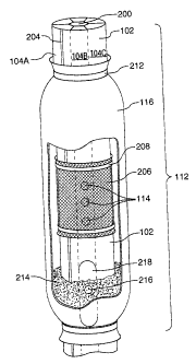
A system 100 includes a central well stock 102, containing two or more
internal
chambers 104, centered in an exploratory borehole 106, as schematically
depicted in Fig. 1.
Expandable packers 108 are spaced along the length of well stock 102. The
packers are
5 preferably bentonite or another expandable material contained within a
permeable, expandable
fabric sock (for example, of nylon or geotextile fabric) and surrounding the
central well stock 102.
Bentonite packers expand upon absorbing water. Accordingly, water can be
provided to the
packers, which will then expand to seal off different sections of borehole 106
from each other, as
seen in FIG. 1B. Isolating sections allows independent samples or measurements
to be taken
from discrete regions. Packers 108 are preferably attached to well stock 102
by ties 110. Ties
110 can be nylon, plastic or metal, or metal or plastic clamps can be used.
Alternative packers,
such as a fluid-filled elastic toroid, can also be used.
Packers 108 define sampling intervals 112 between the packers. In a preferred
embodiment, well stock 102 within sampling interval 112 includes a sample
inlet 114. Sandpack
socks 116 can be placed around the well stock and over the inlets, to filter
the water entering the
well stock. A cutaway close-up of sampling interval 112 is depicted in FIGURE
2, showing a
sandpack 116.
Mufti-chambered well stock 102 includes plural longitudinal chambers 104, as
shown in
Fig. 2. In a preferred embodiment, well stock 102 is a continuous cylindrical
tube of flexible
polyethylene with seven longitudinal chambers, comprising a central hexagonal
longitudinal
channel 200 surrounded by six outer longitudinal chambers, as seen in Fig. 2.
In the preferred
embodiment, the diameter of the central hexagonal channel is roughly 1 /4 of
the diameter of the
well stock. In the preferred embodiment, well stock 102 is about 1.7" in
diameter. In
alten~atives, the well stock outer diameters can be as small as 3/4 inch or as
large as 8 inches. The
CA 02260587 1999-02-02
6
well stock-packer system can be used with borehole or casing diameters as
small as 3/4 inch or
as large as 12 inches. The outer longitudinal chambers are roughly trapezoidal
in cross-section,
with a rounded outer edge.
Well stock 102 is preferably an extruded, medium-density, flexible
polyethylene.
Flexibility allows the well stock to be coiled on a spool and uncoiled into a
well. Use of
polyethylene for the well stock also creates a smooth outer surface, which can
simplify coiling,
storage and deployment of the well stock. Several hundred feet of well stock
can be coiled into
a roughly 5' diameter coil, which can be easily unwound into a borehole.
Coiling the stock also
greatly simplifies well stock storage and transportation. The diameter of the
well stock and the
shape and number of longitudinal chambers can be varied to suit circumstances.
In a preferred embodiment, the well stock is a single continuous piece
extending from the
surface of the ground to the deepest sampling depth. In addition to the
storage and deployment
advantages already mentioned, having one continuous well stock eliminates the
need for joints,
which improves the sampling integrity; joints in such a system must be water
tight, which can be
expensive to implement and difficult to maintain. Joints can also add to the
difficulty of deploying
the MLMW, because jostling can decrease joint integrity.
Well stock 102 also includes a reference groove 204 to aid in the
identification of specific
chambers. Reference groove 204 is preferably scribed into the well stock;
identifying marks or
paint can also be applied to the well stock. Where manufacturing techniques
allow, the well stock
material itself can be color-coded.
In the sampling interval depicted in Fig. 2, three sampling inlets 114 are
shown. For a
given sampling interval, preferably all sampling inlets open into the same
longitudinal chamber,
in this case chamber 104B. In other embodiments, sampling inlets in the same
sampling interval
can open into different chambers. In the system shown in Fig. 2, sampling
inlets 114 are covered
CA 02260587 1999-02-02
with a wire mesh 206 secured to well stock 102 by nylon ties 208. Ties 208 can
alternatively be
made of metal or other material A sand pack 116, secured by nylon ties 212 and
containing sand
214, covers inlets 114. Wire mesh 206 and sand pack 116 filter the sample on
its way into inlets
114. A sealant hole 216 is also shown in Fig. 2. A sealant is injected into
sealant hole 216 to
prevent liquid in chamber 104B from flowing below sealant hole 216.
FIGURE 3 is a depiction ofthe central well stock of FIGURES lA and 1B. In
Figure 3,
inlets 114 at different points along the length of the well stock, open into
separate chambers. As
schematically shown in Fig. 3, in actual use inlets 114A-114C would typically
be farther apart than
the scale of the drawing allows. Inlet 114A opens into chamber 104A, inlet
114B opens into
chamber 104B, and inlet 114C opens into chamber 104C. In one embodiment, when
installed,
packers would be used to isolate inlets 114A, 114B and 114C into three
respective sampling
intervals. Sealant, preferably inert, can be injected into holes below at
least one selected inlet.
Enough inert sealant is injected to block the longitudinal chamber so that the
fluid sample cannot
pass the sealant. In alternative embodiments, packers are not used. Also in
alternative
embodiments, a user can define a greater number of sampling intervals than
longitudinal chambers
by isolating longitudinal portions with a longitudinal chamber by injecting
sealant above and below
an inlet. The corresponding sections ofthe annulus between the well stock and
the borehole wall
can then be isolated by sealing using packers or, if the desired sampling
intervals are not long
enough for packers to be practical, then isolating layers, such as of grout,
bentonite, or sand can
be used. The isolating materials can be delivered by conventional methods such
as tremie, or via
one or more longitudinal chambers.
Alten~ative embodiments for well stock 102 are shown in FIGURES 4A- 4E. Figure
4A
shows extruded tubing 402 including internal openings 404. In the embodiment
depicted in Fig.
4A, the tubing 402 and openings 404 have been extruded as a single piece. In a
preferred
CA 02260587 1999-02-02
8
embodiment, the openings have a diameter of roughly 5/8". Openings can be
sized somewhat
smaller or much larger, as sampling or monitoring needs dictate.
Fig. 4B shows small tubes 406 contained within an outer sheath 408. Small
tubes 406
have an inner diameter of roughly 5/8". Outer sheath 408 can be an elastomeric
material such as
rubber, vinyl, or silicone. Alternatively, outer sheath 408 can be a flexible
plastic or metal. Small
tubes 406 can be threaded into sheath 408 or, alternatively, tubes 406 can be
bundled and sheath
408 wrapped around and sealed. Inlets can be cut, burned or otherwise provided
in the tubes and
outer sheath. In a preferred embodiment, sampling intervals are defined and
inlets open into only
one tube per sampling interval.
Figures 4C-4E show the formation of an alternative embodiment of a well stock
by
embedding tubes 410 in a plastic, preferably polyethylene, block 412. In this
embodiment, tubes
410 are embedded into block 412 by the application of heat. The polyethylene
block is then heated
and shaped, as shown in figure 4D. In the final step, block 412 is formed into
a cylinder and
sealed with a seam 414, as depicted in Figure 4E.
In an ahernative, well stock 102 can be injection-molded around tubes or
channels. In all
embodiments of well stock 102, the internal chambers allow for the collection
of groundwater or
soil vapor samples using small-diameter pumps or bailers, and finding the
depth of the static
groundwater using a conductance meter or other water-level measurement tool.
As will be
apparent to those skilled in the art, other instruments, such as pressure
transducers, geochemical
sensors, tensiometers, suction lysimeters, dissolved oxygen meters, interface
probes, check valves,
and optical sensors can be placed within longitudinal chambers 104. A small
camera can also be
placed in a chamber.
After the desired groundwater sampling intervals have been determined (for
example by
evaluating subsurface hydrogeologic and geochemical data), inlets or ports in
the internal
CA 02260587 1999-02-02
9
chambers are made to allow groundwater or soil vapor to pass in. In a
preferred embodiment,
the sampling inlets open into oily one chamber per sampling interval. However,
the invention
comprises plural sampling inlets opening into plural chambers in one interval.
To reduce the
entrance of sediment into the sampling chambers, the ports are covered with
filtering material.
Sample filtration can also be accomplished using a column of fine-grained sand
that is positioned
around the sample port inside of a geotextile filter fabric sock (or similar
material) affixed to the
monitoring well stock with ties, clamps, or other methods of attachment.
In one embodiment, a packer is used to seal the annular space between the
central well
stock and the borehole wall between the monitoring intervals to prevent cross-
contamination.
This is done using bentonite packers 108 that include mined bentonite chips or
bentonite that has
been compressed into pellets, contained within a permeable, expandable fabric
sock affixed to the
central well stock using ties 110, as shown in Fig. 1. The permeable fabric
allows water to enter
the packer from all sides, preventing the bentonite first exposed to water
from becoming saturated
and impermeable. Other permeable materials can be used for covering packers
108. The roughly
spherical shape of the chips or pellets ensures slow expansion and allows the
water to distribute
evenly to all chips or pellets, Compressed pellets absorb water more quickly
than uncompressed
bentonite, allowing regulation of the water absorption and helping avoid such
saturation and
impermeability. In this way, the saturation difFlculties discussed in U.S.
Patent No. 5,195,583 to
Toon et al. are obviated, and no intra-packer water distribution system, such
as Toon's blotting
paper or tiny pipes, is necessary. The compressed bentonite pellets are
preferably Volclay Pure
Gold 114 Inch Bentonite Tablets manufactured by CETCO (Colloid Environment
Technologies
Co.), located at 1500 West Shure Dr., Arlington Heights, IL 60004. Spherical
bentonite pellets
can be as small as grains of sand.
In a variation, the bentonite is formed into pellets that are coated in
various thicknesses
CA 02260587 1999-02-02
with a water-soluble material. As the water-soluble material dissolves around
a pellet, that pellet
expands. By using various thicknesses of coating, a time-release expansion can
be used to delay
hydration and expansion of the packers. The coated pellets are preferably
Pelplug manufactured
by PDS Co., P.O. Box 507, El Dorado, AR 71731. Another embodiment of the
invention uses
5 packers constructed of sheets of pressed bentonite mats (or other expandable
sheets) that are
wrapped around and are secured to the central well stock. They can be enclosed
in fabric socks.
Compressing the bentonite into mats also allows for even water distribution.
The bentonite
packers can be hydrated by exposure to groundwater, or a longitudinal chamber
can be used to
hydrate the packers. In the latter embodiment, holes are drilled into the
chamber and spaced
10 along the length of the well stock where the packers will be placed. The
packers are placed on
the well stock, and water can be introduced into the hydrating chamber at the
surface. If the
system is used with pneumatic packers or other devices that use fluid, the
fluid can be introduced
through one of the chambers, and the packer expansion can be controlled from
the surface. In
other alternatives, the packer sock can be of an elastomeric material such as
rubber, silicone, or
vinyl, and including plural openings to allow hydration.
The MLMW is installed in a borehole, temporary casing, or existing well. In a
preferred
method in accordance with the invention, the entire assembled MLMW is lowered
into the ground
during installation. The well stock can be uncoiled, the bentonite packers and
optional sand packs
attached, and the MLMW lowered into the existing hole. In a preferred
embodiment, the
diameter of a system including well stock, unhydrated packers, and sand-pack
containers is
roughly 3 inches, small enough for the assembled MLMW to be lowered into a
small-diameter
casing, well, or hole in the ground without obstruction, as shown in Fig. lA.
When the bentonite packers contact water -- either groundwater, water
introduced into
the well, or water introduced from the surface from a longitudinal chamber --
they slowly expand
CA 02260587 1999-02-02
11
over a period of several hours, filling and completely sealing the annular
space between the central
well stock and borehole or well casing, as seen in Fig. 1 B. When there is a
casing, it can be
removed after the unhydrated well stock assembly is inserted into the hole.
The smooth exterior of the extruded polyethylene well stock allows the
bentonite packers
to be attached to the well stock virtually gap-free. The gap-free attachment
prevents water from
leaking between the packer and the well stock, thus maintaining sample
integrity. The bentonite
packers expand to fill irregularities in the borehole wall, also maintaining
sample integrity. Using
bentonite packers effectively seals the borehole without the use of time-
consuming and potentially
sample-disruptive tremie procedures. In alternatives, fluid-filled packers or
packers filled with
other expandable materials can be used. Thus, the borehole (or well) is sealed
and groundwater
samples can be collected and groundwater pressures can be accurately measured
in independent
intervals in the borehole or well. Groundwater samples can be collected from
the chambers
using, for example, small-diameter bailers, check valve tubing pumps, or
peristaltic pumps.
Water levels can be measured using electronic well sounders. Pressure head can
be measured
using a piezometer or other transducer. Hydraulic tests, including slug,
extraction, injection, and
pressure pulse tests, can be performed. In situ geochemical analysis using
geochemical probes
inserted into the chamber can be performed.
Three alternative methods of installation are preferred. A first method 500 is
depicted in
FIGURE 5. After sampling intervals have been determined, for example, by
evaluating subsurface
hydrogeologic and geochemical data by reference to the boring log, ports are
drilled, at a step
502, into selected chambers at appropriate points to allow groundwater or soil
vapor to pass into
the longitudinal chambers at desired depths when the well stock is installed.
As has been
discussed, in a preferred embodiment, only one chamber is used per sampling
interval. The ports
can be covered with filtering fabric, at an optional step 504, and sandpacks
can be added, at an
CA 02260587 1999-02-02
12
optional step 506. A borehole is drilled by hollow stem auger, rotary drill,
or other means. Well
stock 102 is inserted, at a step 508, inside a hollow stem auger or a rotary
drilled boring.
Alternating lifts of sand and bentonite seals are installed, at a step 510.
The annular materials can
be installed by tremie or dropped from the surface. Centralizers can be used
to centralize the well
stock in the auger or boring. Readings or samples are taken, at a step 512.
A second method 600 of installation is depicted in Fig. 6. Openings are made
in well
stock 102, at a step 602. At least one unhydrated bentonite packer is
attached, at a step 604.
Mesh filters 206 and sand packs 116 can optionally be attached, at steps 606
and 608,
respectively. The well stock with unhydrated bentonite packers 108 and sand
packs 116 attached
is introduced, at a step 610, into a borehole, as schematically shown in Fig.
lA. Bentonite
packers 108 are hydrated by native or introduced water, at a step 612, sealing
the annulus
between the stock and the hole, and defining at least one sampling interval.
Samples and/or
readings are then taken, at a step 614. This method is the preferred
installation for use with direct
push equipment.
A third method 700 of installing the well stock is depicted in FIGURE 7. This
method is
preferred in some unconsolidated soil formations such as homogeneous heaving
sands where the
hole is surrounded by a casing. Openings are made in well stock 102, at a step
702. Mesh
filters 206 and sand packs 116 can optionally be attached, at steps 704 and
706, respectively. The
well stock is inserted, at a step 708, down a casing. When the casing is
withdrawn, the sand
collapses around the well stock and mesh screens, supporting the well stock.
The casing is
withdrawn, at a step 710. Samples and/or readings are then taken, at a step
712.
The well stock can be manufactured of Teflon, other plastics besides
polyethylene, or
metal, depending on the user's needs and site characteristics. The well stock
can be taken out,
redrilled and/or resealed, and put back. Inlet holes and ports can be
installed in ways other than
CA 02260587 1999-02-02
13
drilling, as for example, by cutting or by melting a hole into the plastic
stock. Inlets can transmit
fluid in either direction; in general, inlets can be used as ports to transmit
materials either into or
out of the chamber. Materials need not flow, but can be injected under
pressure. Materials
transported in the well stock chambers from the surface need not be fluids.
For example, sand
or grout could be placed within a chamber at the surface and would flow (or be
injected) down
the chamber and out of an inlet at a desired depth. This procedure could be
done at the
completion of monitoring when removal of the mufti-level well was desired. In
this way, the
mufti-level well fiznctions as a tremie pipe (i.e., the grout is pumped
through the tubing as it is
withdrawn to seal the borehole. Other materials, such as dyes or markers or
remediation
compounds, such as oxygen- or hydrogen- releasing compounds, can be injected
or introduced
through a longitudinal chamber of the well stock . Beneficial bacteria could
also be introduced
through the well stock.
Alternative embodiments of the well stock, including longitudinal chambers,
and other
components can be scaled up or down to the system limit dimensions. The
longitudinal chambers
can be larger or smaller than the roughly 5/8" diameter described supra. For
example, in a eight-
inch diameter well stock, each chamber can be approximately 1 2/3 inches in
diameter. In a 3/4-
inch diameter well stock, the chambers can be less than 1 /4 inch in diameter.
Preferably, well stock 102 includes at least 6 longitudinal chambers, but the
number of
chambers can be increased or decreased depending on the user's needs. The
chambers need not
be hexagonal, trapezoidal, or round, but can be any shape that suits the
user's manufacturing
capabilities, storage or transportation requirements, or in-ground needs. The
well stock can be
used to send fluids in either direction or in different directions
simultaneously. For example, fluid
dye from the surface can be injected down one longitudinal chamber while a
sample is drawn out
to the surface from another. The system can be used for sampling, monitoring,
introducing and
CA 02260587 1999-02-02
14
injecting. The system need not be installed vertically in a borehole, but can
be installed in other
orientations, such as horizontally in a trench. In one embodiment, the pellets
can be coated with
a material soluble in a solvent other than water, and the solvent can be
introduced through a
chamber in the well stock.
While there has been described what is believed to be the preferred
embodiments of the
invention, those skilled in the art will recognize that other and further
modifications may be made
thereto, and it is intended to claim all such embodiments that fall within the
true scope of the
invention.