Note: Descriptions are shown in the official language in which they were submitted.
~ CA 02260588 1999-02-02
FLEXIBLE CONTAINER WITH INTERNAL BAFFLES
TECHNICAL FIELD
The present invention relates to a flexible container having a support
system comprising internal baffles for assisting in maintaining the shape of
the
container when it is filled with a material.
BACKGROUND OF THE INVENTION
Flexible containers are commonly used for the handling, storage and
transportation of flowable materials. These containers are typically designed
to be
rectangular in cross-section so that they form "cubes" when filled which can
be
packed efficiently into storage and transportation facilities such as trucks
and
warehouses, minimizing the amount of wasted space that may result from other
shapes.
Unfortunately, flexible containers have an inherent tendency to bulge
when filled so that they do not maintain their intended shape. This bulging
typically results in the container having rounded corners and sides which are
not
straight. This in turn results in the containers being more difficult to
handle and
store efficiently.
It is well known in the art of flexible containers to employ devices or
systems for adding structural support to the container for the purpose of
assisting in
maintaining the shape of the container.
For example, U.S. Patent No. 5,076,710 (Derby), U.S. Patent No. 5,165,802
(Derby), U.S. Patent No. 5,222,812 (Cuddy et al), U.S. Patent No. 5,328,267
(Cuddy et
al), U.S. Patent No. 5,468,528 (Shnaars et al), U.S. Patent No. 5,556,205
(Gallie), U.S.
Patent No. 5,564,833 (Proffitt) and U.S. Patent No. 5,685,644 (Taylor) all
describe the
use of "corner baffles" which span adjacent sides of flexible containers in
order to
add support to the container. These corner baffles include apertures of a
variety of
shapes such as circles, rectangles, diamonds and triangles for permitting
material to
-1-
' CA 02260588 1999-02-02
pass between sides of the baffles. A variety of different configurations for
the baffles
is described in these references, but all are attached such that in a
rectangular shaped
container, there are eight locations of connection between the baffles and the
side
walls of the container.
U.S. Patent No. 5,071,025 (Boots), U.S. Patent No. 5,289,937 (Boots), U.S.
Patent No. 5,407,090 (Boots), U.S. Patent No. 5,562,227 (Takezawa et al), U.S.
Patent
No. 5,618,255 (Nickell et al) and U.S. Patent No. 5,649,767 (Nickell et al)
all describe
container systems that consist of outer structures and inner structures which
together provide support for the container through the cooperation of the two
structures. Once again, a variety of different configurations for the
structures is
described, but these container systems all tend to be somewhat complicated and
thus
would be difficult or costly to manufacture.
U.S. Patent No. 5,316,387 (Polett et al), U.S. Patent No. 5,328,268
(Lafleur), U.S. Patent No. 5,421,804 (Lafleur), U.S. Patent No. 5,538,155
(Hoekstra),
U.S. Patent No. 5,660,478 (Alack et al), and U.S. Patent No. 5,664,887
(Lafleur) all
describe types of support systems for flexible containers, some of which
include
baffle structures and some of which do not.
U.S. Patent No. 5,316,387 (Polett et al) describes three different
embodiments of a support system. In a first embodiment, a plurality of loops
are
attached to the inside surfaces of the walls of the container at a plurality
of levels. A
rope or the like is then passed through each loop at a level and the rope is
then
joined at its ends. Each loop is separately attached to a wall so that there
are four
attachment points per level for a four sided container. In a second
embodiment, a
plurality of panels are provided, each of which have one edge affixed to the
inside
surface of one wall of the container and extend toward the center of the
container.
The panels are then fastened together at a point at or near the center of the
interior
of the container to define a plurality of separate sections within the
container.
Material is permitted to move between sections at the upper and lower ends of
the
panels. A third embodiment is a hybrid of the first and second embodiments,
and
comprises a plurality of flaps, each of which have one edge affixed to the
inside
surface of one wall of the container. Each flap has a plurality of holes at a
plurality
of levels. A rope or the like is passed through each of the holes at a level
and the
-2-
CA 02260588 1999-02-02
rope is then joined at its ends. The support system in Polett therefore
involves a
significant amount of fabrication effort.
U.S. Patent No. 5,538,155 (Hoekstra) describes a support system
somewhat similar to the hybrid embodiment in Polett in which a baffle "core"
is
provided, which baffle core is contained within the container and is spaced
from the
inner surfaces of the walls of the container by side walls which extend from
the
inner surfaces of the walls toward the center of the container. The baffle
core is
therefore relatively small in comparison with the size of the container, and
fabrication of the container and support structure is made somewhat more
complicated by the inclusion of the side walls. Holes are provided in the
baffle core
to facilitate movement of material into and out of the baffle core.
U.S. Patent No. 5,660,478 (Alack et al) describes a support system
somewhat similar to the first and second embodiments in Polett. In Alack, a
plurality of tension members are provided at different levels in the
container.
These tension members are attached to the walls of the container and either
extend
between opposite sides of the container or between adjacent sides of the
container.
As in Polett, the use of the tension members requires four connection points
per
level for a four sided container.
U.S. Patent No. 5,328,268 (Lafleur), U.S. Patent No. 5,421,804 (Lafleur)
and U.S. Patent No. 5,664,887 (Lafleur) all describe a support system for a
flexible
container which is similar to the first embodiment in Polett, in that closed
loops of
cord are provided around the inner surfaces of the walls of the container at a
plurality of levels. These loops of cord preferably have portions which extend
obliquely between adjacent sides of the container. In the preferred
embodiment, the
cords require a minimum of eight connection points to the walls of the
container
per level in order to provide the oblique portions, thus adding to fabrication
costs.
All of the support systems for flexible containers as detailed above may
add significant cost to the fabrication of the container due to the number and
types
of connections that must be used to attach the support system to the
container.
-3-
CA 02260588 1999-02-02
In addition, the support systems detailed above which include
apertured baffles often permit the passage of material through the baffle but
only
while compromising its structural support properties.
For example, in U.S. Patent No. 5,076,710 (Derby), U.S. Patent No.
5,165,802 (Derby), U.S. Patent No. 5,468,528 (Schnaars et al), U.S. Patent No.
5,556,205
(Gallie et al), U.S. Patent No. 5,564,833 (Profitt) and U.S. Patent No.
5,685,644 (Taylor)
the baffles include a plurality of relatively large apertures spaced
vertically along the
centerline of the baffle. These large centralized apertures facilitate easy
movement
of the material through the baffle but tend to result in bulging of the
container
adjacent to locations where the apertures are positioned because the strength
of the
baffle is compromised at those locations.
In U.S. Patent No. 5,222,812 (Cuddy et al), U.S. Patent No. 5,328,267
(Cuddy et al), U.S. Patent No. 5,538,155 (Hoekstra), the apertures tend to be
smaller
and more evenly distributed on the baffle, resulting in some improvement in
the
strength and thus the support properties of the baffle. This improvement in
strength is offset, however, by the baffle providing a more restrictive
passage for
material due to the relatively small apertures.
U.S. Patent No. 5,618,255 (Nickell et al) and U.S. Patent No. 5,649,767
(Nickell et al) both describe the use of a plurality of "baffle strips" which
are attached
to a liner for the container with spaces between them to permit the passage of
material around the strips. Each baffle strip can thus function as a separate
support
member, with the ability of material to pass around the baffle strips being
governed
by the spacing between the strips. Although the system described in Nickell
addresses the issue of maintaining the support properties of the baffle, and
although
the width of the spacing between the strips could conceivably be adjusted to
facilitate
easy passage of material around the baffle strips, the Nickell system is
relatively
complicated and could as a result be quite costly to manufacture.
As a result, there remains in the art of flexible containers a need for a
flexible container that is relatively easy to manufacture and yet incorporates
a
relatively efficient support system for assisting in maintaining the shape of
the
container when it is filled with a material.
-4-
CA 02260588 1999-02-02
SUMMARY OF THE INVENTION
The present invention relates to a flexible container of the type
comprising a bottom, a plurality of flexible side walls and a plurality of
flexible
baffles. In particular, the invention relates to a flexible container of this
type where
each side wall is comprised of one baffle connection line and wherein each
baffle is
attached to two adjacent side walls along the baffle connections for those
side walls.
In one aspect of the invention, the invention is a flexible container, the
container comprising:
(a) a bottom;
(b) a plurality of flexible side walls projecting from the bottom, the side
walls and the bottom together defining a container space for containing
a material;
(c) one baffle connection line extending along each of the plurality of side
walls; and
(d) a plurality of flexible baffles contained within the container space,
wherein each baffle is attached to two adjacent side walls along the
baffle connection lines for those side walls.
In another aspect of the invention, the invention relates to a method
for constructing a flexible container of the type comprising a bottom, a
plurality of
flexible side walls projecting from the bottom, the side walls and the bottom
together defining a container space for containing a material, and a plurality
of
flexible baffles contained within the container space, and is the improvement
comprising attaching each baffle to two adjacent side walls along a single
baffle
connection line on each of the adjacent side walls.
The baffles are preferably attached to the side walls along seams on the
side walls so that the seams comprise the baffle connection lines along those
side
-5-
CA 02260588 1999-02-02
walls to which baffles are attached. The seams on the side walls may be
interior
seams which are created from inside of the container space. Preferably,
however,
the seams on the side walls are exterior seams which are created from outside
of the
container space.
The baffles may be attached to the baffle connection line in any
manner, including by gluing, melting, welding, riveting or stapling.
Preferably,
however, the baffles are attached to the baffle connection line by stitching
them to
create a seam so that the side walls and the baffles are attached by stitches
which
define the baffle connection line. The stitching is preferably performed from
outside
of the container space so that an exterior seam is formed.
The baffles may be attached to the side walls continuously or
intermittently along the baffle connection line. The baffle connection line
may
extend the full height of the side walls or may extend for only a portion of
the
height of the side walls. Preferably, the baffle connection line extends along
substantially the entire height of the side walls so that the baffles are
attached to the
side walls along substantially the entire height of the container.
The baffle connection lines on the side walls preferably extend in a
direction substantially perpendicular to a plane defined by the bottom of the
container and may be positioned at any location between the edges where side
walls
meet adjacent side walls. Preferably, however, the baffle connection lines are
positioned approximately midway between the edges of the side walls so that
the
baffle connection lines substantially bisect the side walls.
The baffles together when attached to the side walls preferably define
an interior baffle space within the container space and define an exterior
baffle space
within the container space. Preferably, the baffles are attached to the side
walls such
that the interior baffle space adjacent to the baffle connection line on each
side wall
extends substantially to the inner surface of the side wall.
The baffles may either include or not include apertures to facilitate the
passage of material between the interior baffle space and the exterior baffle
space. If
no apertures are provided in the baffles, the baffles preferably are attached
to the side
-6-
CA 02260588 1999-02-02
walls such that material may pass underneath the baffles or over the top of
the
baffles.
Preferably, however, each of the baffles defines at least one aperture for
permitting the material to pass between the interior baffle space and the
exterior
baffle space. More preferably, each of the baffles defines a plurality of
baffle strips
separated by apertures and preferably each of the baffle strips and apertures
extends
substantially between the baffle connection lines. Most preferably, the size
of each
baffle strip and each aperture is substantially the same.
The container may be comprised of any number of side walls and
baffles which are capable of defining the container space. It is not necessary
that the
number of baffles equal the number of side walls. Preferably, however, the
container is comprised of four side walls and four baffles. Each side wall and
each
baffle may be constructed of one panel or piece of material or may be
constructed of
more than one panel or piece of material. Furthermore, more than one side wall
or
baffle may be constructed from a single panel or piece of material.
BRIEF DESCRIPTION OF DRAWINGS
Embodiments of the invention will now be described with reference to
the accompanying drawings, in which:
Figure 1 is a pictorial view of a flexible container according to a
preferred embodiment of the invention;
Figure 2 is a side view of a baffle from the flexible container of Figure 1:
Figure 3 is a transverse section view of the flexible container of Figure 1
taken along line 3-3;
Figure 4 is a transverse section view of the flexible container of Figure 1
taken along line 4-4;
-
CA 02260588 1999-02-02
Figure 5 is a detail section view of a baffle connection line of the
flexible container of Figure 1, taken along line 3-3 of Figure 1;
Figure 6 is a detail section view of a junction of two adjacent side walls
of the flexible container of Figure 1, taken along line 3-3 of Figure 1;
Figure 7 is a detail section view of a junction of two adjacent side walls
of the flexible container of Figure 1, taken along line 4-4 of Figure 1;
Figure 8 is a detail section view of the junction of the bottom and the
discharge chute of the flexible container of Figure 1, taken along line 8-8 of
Figure 3;
Figure 9 is a top plan view of the flexible container of Figure 1.
DETAILED DESCRIPTION
The present invention relates to a flexible container having a support
system comprising a baffle system. The present invention also relates to a
method
of constructing such a flexible container in a relatively efficient and
economical
manner.
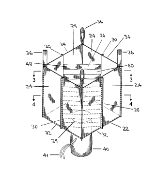
Referring to Figure 1, the invention is comprised of a flexible container
(20). The container (20) comprises a bottom (22), a plurality of side walls
(24) and a
plurality of baffles (26). The container (20) may also include an upper
closure device
(not shown). This upper closure device (not shown) may be comprised of any
suitable structure, device or mechanism permitting the opening and closing of
the
container (20).
The container (20), including the side walls (24), the baffles (26), the
bottom (22) and the upper closure device (not shown) may be comprised of any
material or materials. Preferably the container (20) is comprised of a
flexible or
semi-rigid material such that the container (20) takes the form of a large bag
or sack.
For example, the container (20) may be comprised of woven natural or synthetic
materials.
-g_
CA 02260588 1999-02-02
The container (20) is preferably comprised of one or more polyolefins
such as polypropylene or polyethylene. In the preferred embodiment, the
container
(20) is comprised of woven polypropylene, which is preferably resistant to
ultraviolet light. Depending upon the particular use, it may also be necessary
for the
container (20) to be chemically resistant, hygienic, resistant to
decomposition, have
good breathing properties or have other particular qualities or
characteristics. The
required weight and strength of the woven material will be dependent upon the
size
and required capacity of the container (20). In addition, for certain
applications an
inner sack or lining (not shown) may be placed in the container (20). This
lining is
typically comprised of a moisture proof material such as a polyethylene film.
The side walls (24) project from the bottom (22) so that the side walls
(24) and the bottom (22) together define a container space (28) for containing
a
material (not shown). The flexible container (20) may be comprised of any
number
of side walls (24) which are capable of defining the container space (28). As
a result,
the container (20) may have as few as two side walls (24). There is no upper
limit to
the number of side walls (24). In the preferred embodiment, the container (20)
has
four side walls (24) so that the container is rectangular in transverse cross
section,
thus increasing the efficiency with which multiple containers (20) can be
packed and
stacked.
Each side wall (24) has one baffle connection line (30) which extends
along the side wall (24). In the preferred embodiment the baffle connection
lines
(30) extend in a direction substantially perpendicular to a plane defined by
the
bottom (22) of the container (20). Each baffle (26) is contained within the
container
space (28) and is attached to two adjacent side walls (24) at the baffle
connection lines
(30) for those side walls (24).
It is preferred but it is not necessary that the number of baffles (26)
match the number of side walls (24). For example, there may be as few as two
baffles
(26) spanning as few as three side walls (24), even if the container (20) is
comprised
of more than three side walls (24). If, however, the number of baffles (26) is
less
than the number of side walls (24), the ability of the baffles (26) to provide
structural
support to the container will be compromised. There may also be a larger
number
of baffles (26) than there are side walls (24). If there is a larger number of
baffles (26)
-9-
CA 02260588 1999-02-02
than side walls (24), the "extra" baffles may attach to the container (20) at
the baffle
connection lines (30) or elsewhere.
In the preferred embodiment, however, the number of baffles (26) is
equal to the number of side walls (24) so that there are four baffles (26). As
a result,
in the preferred embodiment the baffle connection line (30) for each side wall
(24)
serves as a junction for two baffles (26), reducing by half the number of
connection
locations in comparison with prior art corner baffle systems which call for
two baffle
connection lines (30) per side wall (24).
The baffles (26) are preferably attached to the side walls (24) along seams
on the side walls (24) of the container (20) so that the seams comprise the
baffle
connection lines (30) for those side walls (24) to which baffles (26) are
attached. The
seams on the side walls (24) may be interior seams which are created from
inside of
the container space (28). In the preferred embodiment, the seams on the side
walls
(24) are exterior seams which are created from outside of the container space
(28). In
this specification, reference to a "seam" includes a seam which consists of
more than
one row of attachment locations.
The baffles (26) may be attached to the baffle connection line (30) in any
manner, including by gluing, melting, welding, riveting or stapling. In the
preferred embodiment, the baffles (26) are attached to the baffle connection
line (30)
by stitching them to create a seam so that the side walls (24) and the baffles
(26) are
attached by stitches which define the baffle connection line (30). The
stitching is
preferably performed from outside of the container space (28) so that an
exterior
seam is formed. In the preferred embodiment, the exterior seams are comprised
of
one or two rows of stitching. Most preferably, the exterior seams are
comprised of
only one row of stitching in order to save on labour and material costs, but
any
number of rows of stitching may be used in constructing the container (20).
There are several methods by which an exterior seam may be created.
For example, the material making up the side walls (24) may simply be gathered
around the baffles (26) at the baffle connection line (30) and the baffles
(26) can then
be attached to the side wall (24) by gluing, melting, welding, riveting,
stapling,
stitching or some other method which can be applied through the gathered
material
-10-
CA 02260588 1999-02-02
to create the seam. The advantage to this method is that the side walls (24)
may be
comprised of as few as one panel of flexible material.
Alternatively, and referring to Figures 1-3, the side walls (24) may be
constructed of more than one panel or piece of material which are connected by
gluing, melting, welding, riveting, stapling, stitching, or some other method
at the
baffle connection lines (30) along the same seam that attaches the baffles
(26) to the
side walls (24).
Interior seams may be created by either of the two above methods or
merely by attaching the baffles (26) to the side walls (24) along the interior
surfaces of
the side walls (24) by gluing, melting, welding, riveting, stapling, stitching
or some
other method without first gathering or separating the side walls (24).
Regardless of whether exterior seams or interior seams are used in the
invention, the side walls (24) of the container may therefore all be comprised
of the
same panel of material, or the side walls may be comprised of any number of
panels
connected together. The preferred number of panels making up the side walls
(24)
will depend upon considerations relating to fabrication costs. The side walls
(24)
and any panels making up the side walls (24) may be connected together in any
manner, including by gluing, melting, welding, riveting, stapling, stitching
or some
other method.
Referring to Figures 1-3 and 8, in the preferred embodiment the side
walls (24) are made up of eight panels, with each side wall (24) being
comprised of
two panels which are stitched together along the seams at the baffle
connection lines
(30) and are stitched to adjacent side walls (24) at the corners defining the
junction
between two side walls (24). In an alternate preferred embodiment, the side
walls
(24) are made up of four panels which are connected together along the seams
at the
baffle connection lines (30) so that each panel forms part of two adjacent
side walls
(24).
The baffle connection lines (30) on the side walls (24) may be located
anywhere between the corners defining the junction between two side walls
(24).
Preferably, the baffle connection lines (30) are located so that the baffles
(26) are
-11-
CA 02260588 2003-O1-09
attached symmetrically within the container space (28). Referring to Figure 1,
in the
preferred embodiment the baffle connection lines (30) are located at or near
the
middle of the side walls (24) so that they substantially bisect the side walls
(24).
Referring to Figure 1, the side walls (24) of the container (20) each have
a height which defines the height of the container (20). Each side wall (24)
has a
lower edge (32) which is joined to the bottom (22) of the container (20) and
an upper
edge (34). The height of each side wall (24) is defined by the distance
between the
lower edge (32) and the upper edge (34).
The seams along which the baffles (26) are attached to the side walls
(24) may extend along any portion of the height of the side walls (24). For
example,
if the baffles (26) do not include apertures to permit material to pass
through the
baffles (26), the seams will preferably not extend along the entire height of
the side
walls (24) so that material can either pass underneath or overtop of the
baffles (26).
Referring to Figure 1, in the preferred embodiment where the baffles (26)
include
apertures, the seams extend substantially along the entire height of the side
walls
(24).
The side walls (24) may be connected to the bottom (22) of the container
(20) in any manner, including by gluing, melting, welding, riveting, stapling,
stitching or some other method. In the preferred embodiment, the side walls
(24)
are connected to the bottom (22) of the container (20) by one or two rows of
stitching
between the lower edges (32) of the side walls (24) and the edges of the
bottom (22).
Referring to Figure 1, the container (20) may also be comprised of at
least one lifting device. Any type of lifting device may be used with the
invention,
but preferably the lifting device is comprised of one or more lift straps
(36). Any
number of lift straps (36) and any type of lift strap (36) may be used, and
the lift straps
(36) may be attached to the container (20) in any manner. The lift straps (36)
may
also be constructed from any material which will adequately support the weight
of
the container (20) when it is full.
In the preferred embodiment, and referring to Figure 1 and Figure (, ,
the container (20) is equipped with four lift straps (36) which are
constructed from
-12-
CA 02260588 2003-O1-09
the same material as the side walls (24), each of which lift straps (36) is
stitched into
an upper corner (38) of the container (20) with one or two roan's of
stitching. The lift
straps (36) are used for handling the container (20) when the container (20)
has been
filled with material.
Referring to Figure 1, the container (20) may also be comprised of a
discharge device for discharging material from the container (20). Any type of
discharge device may be used with the invention, but preferably the discharge
device is located on the bottom (22) of the container (20) so that the
container (20)
can be emptied without being tipped.
In the preferred embodiment, the discharge device is comprised of a
discharge chute (40) which projects downward from an orifice (39) located on
the
bottom (22) of the container (20). This discharge chute (40) is equipped with
a
closure tie (41) which is tied to prevent discharge of material from the
discharge
chute (40) and is untied to permit discharge of material from the discharge
chute
(40).
The discharge chute (40) may be attached to the bottom (22) of the
container (20) in any manner. Referring to Figure 8; in the preferred
embodiment
the discharge chute (40) is formed from one panel of material which is
stitched
together along opposite edges to form a cylinder by creating an external chute
seam
(42} of one or two rows of stitching. The discharge chute (40) is then
attached to the
bottom by creating an external seam of one or two rows of stitching between
the
bottom (22) and the discharge chute (40). Although any material may be used
for the
discharge chute (40), in the preferred embodiment the discharge chute (40) is
constructed from the same material as the side walls (24).
Referring, to Figure 9, in the preferred embodiment the container (20)
when viewed from above includes the container space (28) which is defined by
the
side walls (24) and the bottom (22) of the container (20). The container (20)
also
includes an interior baffle space (44) within the container space (28) and an
exterior
baffle space (46) within the container space (28), both of which are defined
by the
plurality of baffles (26).
-13-
CA 02260588 1999-02-02
One of the features of the preferred embodiment of the invention is
that the interior baffle space (44) adjacent to the baffle connection line
(30) on each
side wall (24) extends substantially to the interior surface of the side wall
(24). As a
result, the cross-sectional area of the interior baffle space (44) is
maximized within
the limits imposed by the size of the container space (28).
The baffles (26) may or may not include apertures to permit material to
pass through them. If the baffles (26) are not equipped with apertures, their
height is
preferably less than the height of the side walls (24) so that material can
either pass
underneath the baffles (26) or overtop of the baffles (26) in order to move
between
the interior baffle space (44) and the exterior baffle space (46).
Preferably each of the baffles (26) includes at least one aperture for
permitting material to pass between the interior baffle space (44) and the
exterior
baffle space (46), in which case the baffles (26) preferably extend along
substantially
the entire height of the side walls (24). Although the aperture or apertures
may be
of any shape or size, small apertures tend to restrict the passage of material
between
the interior baffle space (44) and the exterior baffle space (46), and
apertures which do
not extend substantially across the entire width of the baffle (26) are
believed to
cause bulging of the container (20).
As a result, each baffle (26) is preferably comprised of a plurality of
baffle strips (48) which are separated by apertures (50) and preferably both
the baffle
strips (48) and the apertures (50) extend substantially between the baffle
connection
lines (30) which are spanned by that baffle (26). The function of the baffle
strips (48)
is to provide uninterrupted structural support to the container (20) between
two
baffle connection lines (30) and the function of the apertures is to permit
passage of
material between the interior baffle space (44) and the exterior baffle space
(46).
In the preferred embodiment, a balance is sought between support of
the container (20) by the baffles (26) and permitting relatively unrestricted
passage of
material between the interior baffle space (44) and the exterior baffle space
(46). This
balance is achieved in the preferred embodiment by making each baffle strip
(48)
substantially the same size as each aperture (50) so that the respective areas
of baffle
strip (48) and aperture (50) on each baffle (26) are substantially the same.
-14-
CA 02260588 2003-O1-09
Each baffle (26) of the plurality of baffles (26) may be comprised either of
one piece of material or of a plurality of pieces of material connected
together.
Furthermore, more than one baffle (26) may be comprised of the same panel or
piece
of material. As a result, the plurality of baffles (26) may be comprised of
ane
continuous piece of material, one piece of material for each baffle (26), or a
plurality
of pieces of material for any one baffle (26).
In the preferred embodiment, each baffle (26) is comprised of one piece
of material so that there are four pieces of material making up the four
baffles (26).
Referring to Figure 2 , each baffle (26) is further comprised of a pair of
baffle
connection strips (52) which extend along both side edges of the baffle (26)
for
substantially the entire height of the baffle (26). These baffle connection
strips (52)
facilitate attachment of the baffle (26) to the baffle connection lines (30).
The baffle
strips (48) and the apertures (50) extend between the baffle connection strips
(52).
The invention also relates to a method for constructing the container
(20). In the preferred embodiment of the invention, the container (20) is
comprised
of four side walls (24), four baffles (26), one bottom (22), four lift straps
(36) and one
discharge chute (40). The four side walls (24) are comprised of eight pieces
of
material and the four baffles (26) are comprised of four pieces of material.
The pieces of material making up the container (20) may be connected
together in any manner, including by gluing, melting, welding, riveting,
stapling,
stitching or some other method. In the preferred embodiment, each of the
pieces of
material making up the container (20) are connected with one or two rows of
stitching, although any number of rows of stitching may be used. Most
preferably,
the pieces of material making up the container (20) are connected with only
one row
of stitching in order to save on labour and material costs.
There are eight lines of connection necessary to create and connect the
side walls (24). Four of these lines of connection will be along the four
corners
~~hich define the junctions of the side walls (24) and will be made by
creating
external seams of one or two rows of stitching to connect two side walls (24)
together
and to simultaneously attach one lift strap (36) to each of the earners along
the
-15-
CA 02260588 1999-02-02
upper edges (34) of the side walls (24). The other four lines of connection
will be at
the baffle connection lines (30), and will be made by creating external seams
of one
or two rows of stitching to connect the pieces of material making up the side
walls
(24) and to simultaneously attach two baffles (26) to the baffle connection
lines (30)
along the seams.
The discharge chute (40) is constructed by rolling a piece of material
into a cylinder and then creating the external chute seam (42). The discharge
chute
(40) is then attached to the orifice (39) on the bottom (22) of the container
(20) by
creating an external seam of one or two rows of stitching between the
discharge
chute (40) and the bottom (22). The bottom (22) of the container (20) is then
attached
to the four side walls (24) by creating an external seam of one or two rows of
stitching between the side walls (24) and the bottom (22).
As can be seen, the container (20) of the present invention is very
simple to construct and reduces by half the number of seams that must be
created to
install a baffle system in a flexible container in comparison with most
conventional
prior art flexible containers having corner baffle systems. In addition, in
the
preferred embodiment of the invention the container (20) is constructed
entirely by
creating external seams, thus eliminating the need to create internal seams,
which
add cost and time to the fabrication process.
The container (20) of the present invention also provides a relatively
effective and efficient system for supporting the container (20) due to the
symmetrical placement of the baffles (26) in the container (20). This
efficiency and
effectiveness is enhanced in the preferred embodiment due to the shape and
configuration of the baffle strips (48) and apertures (50) that are provided
in the
baffles (26).
-16-