Note: Descriptions are shown in the official language in which they were submitted.
CA 02260632 1999-01-29
.~., .
SHEET MATERIAL DISPENSING APPARATUS AND METHOD
BACKGROUND OF THE INVENTION
Field of the Invention
The present invention relates to a sheet material dispensing apparatus
and method. More particularly, the present invention relates to an apparatus
and
method for dispensing sheet material from at least one source of sheet
material.
Description of Related Art
A number of different types of sheet materials are dispensed from
dispensers. Typically they are wound into a roll either with or without a core
to
provide a maximum amount of material in a relatively small amount of space.
Some examples of these materials include paper towels, toilet tissue, wrapping
paper, aluminum foil, wax paper, and plastic wrap. Rolled sheet materials are
typically dispensed from dispensers having structure for allowing the roll of
sheet
material to rotate while the material is removed from the roll. Although these
dispensers have been in existence for a long period of time, some of them have
many drawbacks and disadvantages.
In many conventional dispensers for sheet material, a user must rotate a
crank or move a lever each time the user desires to remove material from the
dispenser. This crank or lever typically rotates a roller mechanism for
feeding
the sheet material from the dispenser. Although these types of dispensers are
effective at dispensing sheets of material, a user must make physical contact
with the crank or iever each time the user desires to dispense the sheet
material
from the dispenser. For example, during a single day in an extremely busy
washroom, hundreds or even thousands of users may physically contact a
dispenser to dispense paper toweling therefrom. This leads to possible
transfer
of germs and a host of other health concerns associated with the spread of
various contaminants from one user to another.
Another problem associated with conventional dispensers is that of
maintaining an adequate supply of the rolled sheet material in the dispenser.
In
one type of dispensing system, a housing contains a single roll of material
during
CA 02260632 2006-06-07
dispensing. This type of dispd6ser requires frequent monitoring by a service
attendant to determine when substantially all of the material has been
dispensed
so that a new roll of material may be loaded in the dispenser. When the new
roll
is loaded, the pardally consumed roll is often discarded In place of the new
roll,
resulting in the waste of a significant arnount of usable matarial left on the
par6ally consumed rolL
In an attempt at solving the problem of maintaining an adequate supply
of sheet material, some oonventionai dispensers have a transfer mechanism
allowing far subsequent dispensing from multiple roNs of *sheet material.
Atthough these types of dispensers are sometirnes effeotive at dispensing
substantially all of the materiat from each of the rolls, they are often very
complex, leading to increased cost and reduced reliability.
Lack of control of the length of material dispensed Is another problem
associated with some conventional dispensers. For example, some
conventional dispensgrs include a cutter allowing a user to select a parNcular
fength of sheet material before cutting it away from the remainder of the roll
of
mat,etial. Because a continuous sheet of material can be rapidly removed from
these types of dispensers, more materiel than is necessary may be removed
from the dispenser, resulting in waste. pue to their design, dispensers of
these
types are often noisy and bulky.
Attempts have been rnade to limit the amount of sheet material
continuously dispensgd. For example, U.S. Patent No. 5,630,526 to oodv,
discfoses a
system for dispensing individual segments of sheet material from a roll of
sheet
material having perforated tear lines separating the individual segments.
Pulling
an end-most segmsnt of the sheet material teats the end-rnost segment away
from the remaining material along a perforated tear line separating the end-
most
segment from the remainder of the material. Although this type of dispenser Is
effective, additional features such as multiple roll capacity are lacking.
In light of the foregoirtg, there is a need in the art for an lmpnaved
dispenser and method for dispensing sheet material.
2
CA 02260632 1999-01-29
SUMMARY OF THE INVENTION
Accordingly, the present invention is directed to a sheet material
dispensing apparatus and method that substantially obviate one or more of
the limitations of the related art.
To achieve these and other advantages and in accordance with the
purpose of the invention, as embodied and broadly described herein, the
invention includes an apparatus for dispensing sheet material from at least
one source of sheet material. The apparatus includes a housing defining an
interior including a first section for a first source of sheet material and a
second section for a second source of sheet material, and an outlet though
which an end portion of sheet material is dispensed from at least one of the
sources. At least one nipping surface is disposed in the housing. A nipping
element is pivotally mounted in the housing so that the nipping element pivots
between a first position in which a first portion of the nipping element and
the
nipping surface form a nip for the end portion of sheet material, and a second
position in which at least a second portion of the nipping element and the
nipping surface form a nip for the end portion of sheet material.
In another aspect, the apparatus includes a sensor for sensing the
amount of sheet material of the first source of sheet material, the sensor
includes at least one cam surface moving in response to a change in size of
the first source of sheet material. At least one cam follower cooperates with
the nipping element. The cam follower contacts the cam surface and the cam
surface moves with respect to the cam follower to control movement of the
nipping element.
In an additional aspect, the apparatus includes at least one isolating
element movably mounted in the housing. The isolating element moves
between a second source isolating position in which the isolating element
positions the second source away from the nipping surface and a second
source dispensing position placing the second source on the nipping surface.
In another aspect, the apparatus includes a housing defining an interior
for accommodating a quantity of sheet material therein and an outlet through
which the sheet material is dispensed. The housing includes a first housing
3
CA 02260632 1999-01-29
member, a second housihg member, and at least one hinge member allowing
the first housing member to pivot with respect to the second housing member
between a closed position limiting access to the interior of the housing and
an
open position allowing access to the interior of the housing. A latch is
provided on the housing for selectively retaining the first housing member in
the closed position. At least one biasing element cooperates with the first
and second housing members. The biasing element biases the first housing
member toward the closed position when the first housing member moves to
the open position so as to limit free movement of the first housing member to
the open position.
In yet another aspect of the invention, the apparatus includes a
housing defining an interior for including a first section for a source of
sheet
material and a second section for the source of sheet material, the second
section being larger than the first section, and an outlet through which the
sheet material is dispensed. A sensor is disposed in the housing for sensing
the size of the source while the source is in the second section. An indicator
cooperates with the sensor to provide an indication when the size of the
source is small enough to place the source of sheet material in the first
section of the housing.
In a further aspect, the apparatus includes a lever pivotally coupled to
the housing and cooperating with a roller so that pivoting of the lever
rotates
the roller, the lever being located with respect to the outlet so that sheet
material dispensed through the outlet passes substantially over the lever.
In another aspect, the present invention includes a method of
dispensing sheet material, including dispensing sheet material from the first
source, the dispensing including passing an end portion of sheet material
from the first source through a nip formed between the nipping element and
the nipping surface and through the outlet: The nipping element is moved
with respect to the nipping surface to place an end portion of sheet material
from the second source in the nip formed between the nipping element and
the nipping surface. The method also includes dispensing sheet material
from the second source, the dispensing of sheet material from the second
4
CA 02260632 1999-01-29
source including passingthe erid portion of the sheet material from the
second source through the nip and through the outlet.
In another aspect, the method includes the steps of positioning the
second source away from the nipping surface and dispensing sheet material
from the first source, the dispensing including passing an end portion of
sheet
material from the first source through a nip formed between the nipping
element and the nipping surface and through the outlet. The size of the first
source is sensed and the second source is placed on the nipping surface
when a predetermined size of the first source is sensed. The method also
includes dispensing sheet material from the second source, the dispensing of
sheet material from the second source including passing an end portion of
sheet material from the second source through the nip and through the outlet.
In another aspect, the method includes the steps of sensing the size of
a source of sheet material and providing an indication when the size of the
source is small enough to place the source in the first section of the housing
interior.
In a further aspect, the method includes placing a first roll of sheet
material in the first section of the housing, and placing a second roll of
sheet
material in the second section of the housing so that the second roll of sheet
material is on the roller. A terminal end of sheet material from the first
roll is
positioned in a nip formed between the roller and the nipping element, and a
terminal end of sheet material from the second roll is positioned between the
roller and the nipping element at a location outside of the nip. Sheet
material
from the first roll is dispensed by passing the terminal end portion of sheet
material from the first roll through the outlet, and sheet material from the
second roll is dispensed by passing the terminal end portion of sheet material
from the second roll through the outlet.
In an even further aspect of the invention, the apparatus includes a
contacting element for contacting an outer surface of a first roll to apply a
force capable of resisting rotational movement of the first roll and
preventing
translational movement of the first roll throughout the dispensing of sheet
material from the first roll.
CA 02260632 1999-01-29
In an even further aspecf of the invention, there is provided a system
for dispensing sheet material from at least one rotatably mounted roll of
sheet
material having a width of at least about 5 inches, the system includes a
dispenser housing including an interior which includes a first section for a
stub
roll of the sheet material and a second section for a reserve roll of the
sheet
material and an outlet through which the sheet material is dispensed; wherein
the system is capable of dispensing a single segment of the sheet material by
a user grasping only the sheet material of the system; wherein dispensing of
a single segment of the sheet material produces a maximum sound level
below about 81 decibels.
In another aspect of the invention, there is provided a system for
dispensing sheet material product from at least one rotatably mounted roll of
sheet material having a width of at least about 5 inches, the system includes
a dispenser housing including an interior which includes a first section for a
stub roll of the sheet material and a second section for a reserve roll of the
sheet material and an outlet through which the sheet material is dispensed;
wherein the system is capable of dispensing a single segment of the sheet
material by a user grasping only the sheet material of the system; wherein the
ratio of the maximum sheet material volume to the total enclosed volume of
the dispenser is at least about 35%.
It is to be understood that both the foregoing general description and
the following detailed description are exemplary, and are intended to provide
further explanation of the invention as claimed.
BRIEF DESCRIPTION OF THE DRAWINGS
The accompanying drawings are included to provide a further
understanding of the invention and are incorporated in and constitute a part
of
this specification. The drawings illustrate embodiments of the invention and,
together with the description, serve to explain the principles of the
invention.
In the drawings,
Fig. 1 is a front perspective view of the sheet material dispensing
apparatus with a front cover of the apparatus in a closed position;
6
CA 02260632 2007-09-11
Fig. 2 is a front perspective view of the apparatus illustrating sheet
materiai being dispensed through a dispensing outiet in the front cover.
Fig. 3a is a front perspective view of the apparatus with the front cover
opened to reveal the interior of a housing of the apparatus;
Fig. 3b is an exploded perspective view showing components mounted to
the rear casing of the housing;
Fig. 4 is a front perspective view similar to Fig. 3a, showing a reserve roll
of sheet material accommodated in a section of the housing;
Fig. 5 is a view similar to Fig. 4 with a sheet.advancing lever of the
apparatus pressed toward a rear of the housing to rotate rollers;
Fig. 6 is a view similar to Figs. 4 and 5 showing a canvming element
pressed toward a bottom of the housing and the sheet advancing lever
pivoted away from the rear of the housing to allow a core of a stub roll to be
removed from the housing Interior while the reserve roll is in the housing;
Fig. 7 is a front perspective view of the apparatus with the front cover
open and a stub roll sensor in a position allowing placement of the stub roll
in
a section of the housing interior
Fig. 8 is an exploded perspective view of a mechanism for rotating the
reserve roll in the housing;
Fig. 9 is a perspedive view of the rotating mechanism of Fig. 8;
Fg.10 is a perspecUve view of a one way clutch mechanism shown in
Figs. 8 and 9;
Figs. 11 and 12 are exploded perspec[ive views of the one way dutch
mechanism shown in Figs. 8-10;
Fig. 13 is an exploded perspective view of a transfer mechanism and
reserve roq sensor for the apparatus;
Fig. 14 is a partlally exploded, perspective view of components of the
front cover induding the mechanism and sensor shown in Fg.13;
Fig.15 Is a perspective view of the front cover shown in Fig 14;
Fig. 16 is a schematic side view of the interior of the housing duMg
initial dispensing from the reserve roll of sheet material;
7
CA 02260632 2007-09-11
Fig. 17 is a view, similar to Fig. 16, showing dispensing from the
reserve roll when the reserve roll reaches a diameter sufficient to place the
reserve roll In a stub roll compartment of the housing interior;
7a
CA 02260632 2007-09-11
Fig. 18 is a view, simlar to Fig. 16, showing dispensing from a stub roll
after the stub roll is placed in the stub roil compartment and a new reserve
roll
is loaded in the housing;
Fig. 19 is a view, similar to Fig. 16, showing dispensing from the stub
roll just before transfer to the reserve roil;
Fig. 20 is a view, similar to Fig. 16, showing dispensing from both the
stub roll and the reserve roll after transfer to the reserve roll;
Fig. 21 is a view, similar to Fig. 16, showing the reserve roll sensor and
an indcator located in the housing during ini6al dispensing from,the reserve
roll;
Fig. 22 is a view, similar to Fig. 17, showing the indicator extending
through an opening in the housing when the reserve roli is a predetermined
size;
Fig. 23 is a partially schematic side view of the irtiterior of the housing
with the front cover opened to place the indicator in a nonindication
position.
Fig. 24 is a schematic internal front view showing sheet material passing
through a nip and the outlet of the apparatus;
Fig. 25 is a partially schematic side view showing testing conditions for
measuring sound level during dispensing from the apparatus; and
Fig. 26 is a schematic side view of an alternate embodiment of the
apparatus in which mating rollers form a nip for sheet material.
DESCRIPTION OF THE PREFERRED EMBODIMENT
Reference will now be made in detail to the present preferred
embodiment of the invention, an example of which is illustrated in the
accompanying drawings. Wherever possible, the same reference numbers are
used in the drawings and the description to refer to the same parts.
In accordance with the invention, there is provided an apparatus for
dispensing sheet material. As shown in Figs. 1, 2, and 3a, apparatus 10
includes a housing 12 having a first housing member 14, a second housing
member 16, and a hinge member 18. Preferably, the first housing member 12 is
a front cover having material dispensing outlet 38 in a lower portion of the
8
CA 02260632 2007-09-11
cover 12, the second housing member 16 is a rear casing, and the hinge 18
member is located at the lower portion of the front cover 12. Preferably, the
rear casing 16 includes mounting holes 17, shown in Figs. 3a and 7, so that
the
housing 12 can be secured directly or indirectly to a mounting surface with
fasteners and/or a releasable mounting bracket (not shown).
The hinge member 18 allows the front cover 14 to pivot with respect to
8a
CA 02260632 2007-09-11
the rear casing 16 between an open position, shown in Figs. 3a, 4-7 and 23,
allowing access to an interior of the housing 12, and a closed position, shown
in Figs. 1, 2, and 16-22, limiting access to the interior of the housing 12.
The
hinge member 18 includes hinge pins 20a and 20b, shown in Figs. 3a, 14, and
15, extending respectively through first hinge brackets 22a and 22b on the
front cover 14 and through second hinge brackets 24a and 24b, shown in
Fig. 1, on the rear casing 16. The front cover 14 pivots about a common axis
of the hinge pins 20a and 20b during movement between the open position and
the closed position.
As shown in Figs. 14 and 15, biasing elements 26a and 26b are
provided respectively about the hinge pins 20a and 20b. The biasing
elements 26a and 26b are preferably torsion springs having ends contacting
the rear casing 16 and the front cover 14 when the front cover 14 is
connected to the rear casing 16. During movement of the front cover 14 to
the open posrtion, the biasing elements 26a and 26b rotationally bias the
front
cover 14 toward the closed position. This rotational biasing of the biasing
elements 26a and 26b restricts free rotation of the front cover 14 toward the
open position and thereby limits forcible impacting of the front cover 14
against a mounting surface when the front cover 14 is opened. In contrast to
conventional dispensers, the biasing elements 26a and 26b minimize the risk
of structural and! or cosmetic damage to both the front cover 14 and a
mounting surface during opening of the front cover 14.
A releasable latch mechanism 28, shown in Figs. 3a, 3b, 4-6, 14, and
15, is provided on the front cover 14 to retain the front cover 14 selectively
in
the closed position shown in Fig. 1. The releasable latch mechanism 28
engages a catch 30, shown in Figs. 3a and 3b, on the top of the rear casing 16
when the front cover 14 is closed. The latch mechanism 28 and catch 30 may
be any type of conventional latching structure used for dispensers. For
example, the latch mechanism 28 may be lock actuated by a corresponding key
(not shown) to iimit unauthorized access to the interior of the housing 12.
Preferably, the housing 12 defines an interior for accommodating one
or more sources of sheet material. Each source preferably includes sheet
9
CA 02260632 2007-09-11
material wound in a cylindrical shaped roll either with or without a core.
Alternatively, each source of sheet material is in an accordion folded stack
or
any other form allowing for uninterrupted, continuous feed.
As shown in Figs. 18 and 23, the housing 12 defines an interior having
a section for accommodating a stub roll of sheet material S and section for
accommodating a reserve roll of sheet material R. The stub roll of sheet
material S rests on a lower surface of the rear casing 16. This lower surface
of the rear casing 16 includes a plurality of ribs 32, shown in Fig. 7, to
limit
frfction between the rear casing 16 and the stub roll S when the stub roll S
rotates in the housing 12 during dispensing of sheet material from the stub
roll. The ribs 32 also elevate the stub roll S from the bottom of the housing
12
to limit possible contact of the stub roll S with any moisture or dirt
accumulated in the housing 12.
As shown in Figs. 3a, 3b, and 7, the interior of the housing 12 includes
a pair of arms 34a and 34b having respective mounts 35a and 35b for
mounting the reserve roll R in the interior of the housing 12 so that the
reserve
roll is placed on rollers 44a-44d, described below, during dispensing of sheet
material from the reserve roll R as shown in Fig. 3b, the arms 34a and 34b are
pivotally mounted to a rear wall of the rear casing 16, as shown in Figs. 16-
22,
to move the reserve roll R in an arc-shaped path during dispensing of sheet
material from the reserve roll R, as shown in Figs. 16 and 17. For example,
the
pair of arms 34a and 34b are end portions of a U-shaped wire structure
mounted to the back wall of the rear casing 16 so that the pair of arms 34a
and
34b pivot in unison. The mounts 35a and 35b allow the reserve roll R to rotate
about its axis of rotation during dispensing of sheet material therefrom. The
mounts 35a and 35b are preferably connected to end portions of the arms 34a
and 34b and are shaped to fit within a core of the reserve roll R.
Tensioning elements 36a and 36b, shown in Figs. 3a, 3b, and 7, are
also connected to end portions of the arms 34a and 34b, respectively. The
tensioning elements 36a and 36b each have a planar surface, for contacting a
respective end of the reserve roll R mounted in the mounts 35a and 35b. These
surfaces of the tensioning elements 36a and 36b apply frictional thrust
CA 02260632 2007-09-11
forces to opposite ends of the reserve roll R to limit free rotation of the
reserve
roll R and thereby induce tension in sheet material pulled from the reserve
roll R
during dispensing. As shown in Figs. 3a, 3b and 7, the tensioning elements 36a
and 36b have portions 37a and 37b for extending beyond the diameter of the
reserve roll R in the vicinity of where the reserve roll R contacts the
rollers 44a-
44d to limit lateral travel of sheet material dispensed from the reserve roll
R.
In a preferred practice of the invention, each of the stub roll S and the
reserve roll R is a continuous web of sheet material wound into a roll either
with or without a core. The sheet material has two side edges, a terminal
end, and an initial end. The sheet material is preferably divided into a
plurality of individual sheets by a plurality of perforation tear lines
including
frangible bonds and perforations spaced along each tear line and extending
from one edge to the other. The spacing and size of the frangible bonds may
be constant or variable across the width of the roll. The perforation tear
lines
are preferably aligned substantially parallel to each other and substantially
perpendicular to the edges of the roll. For example, the sheet material may
be constructed like the sheet material disclosed in above mentioned U.S.
Patent No. 5,630,526, or like the sheet material disclosed in U. S. Patent No.
5,704,566 to Schutz et al.
Although rolls of sheet material having perforation tear
lines are preferred, other types of sheet material may be used in the
apparatus 10.
Preferably, the sheet material of the reserve roll R and stub roll S is
absorbent paper toweling. However, many different types of sheet material
are capable of being dispensed from the apparatus 10. The sheet material
may be formed in many different ways by many different processes. For
example, the sheet material 10 could be a woven material or fabric, like most
textiles, or a non-woven materiaf. A non-woven is a fabric-like materiat
composed of a conglomeration of fibrous materials and typically non-fibrous
additives. Non-wovens may be classified further into wet formed materials
and dry-formed materials. As used herein, wet formed materials are those
11
CA 02260632 2006-06-07
materials formed from an=aque6us or predominantly aqueous suspension of
natural fibers, such as vegetable, mineral or animal, or synthetic fibers, or
combinations thereof by draining the suspension and drying the resulting
mass of fbera; and dry-formed materials are those materials formed by other
means such as air-laying, carding or spinbonding without first forming an
aqueous suspension. Dry-formed non-wovens may,=further Include
composites af wet and dry formed materlais where the composite Is formed
by means such as hydroentangling or laminating.
Preferably, the sheet mater9al of the stub roll S and reserve roll R is
constructed like the sheet material disclosed in U.S. patent No. 8,228,454.
As shown in Fig. 2, the sheet material is dispensed from the interior of
the housing 12 via the dispensing outiet 38 in the lower portion of the front
cover 14. As shown in Figs. 2 and 4, the dispensing outlet 38 Is defined at
least partially by a lower edge of the front cover 14 including vertical
curved
walls 40a and 40b and horizontal planar walls 42a and 42b. The curved walls
40a and 40b provide ease of access to the dispensing outlet 38 and make it
easier for a userto grasp an end portion of sheet material extending from the
outlet 38 without touching the housing 12. End edges of the curved surfaces
40a and 40b are preferably located equidistant from the r.enterline of sheet
material being dispensed from the outlet 38.
Preferably, the width of the dispensing outlet 38 is narrower than the
width of sheet material being dispensed through the opening 38 so that the
edges of the sheet material experience Increased tensile forces Induced by
frictional forces as the sheet material passes through the outiet=38, as shown
in Fig. 2. The distance A, shown in Fig. 4, between the edges of the walls
40a, 42a and the edges of walls 40b, 42b Is preferably between about 20 and
about 90 percent of the sheet material width 8, more preferably between
abo,.rt 60 and about 80 percent of the sheet mater9al width B, even more
preferably between about 65 percent and about 75 percent of the sheet
12
CA 02260632 2007-09-11
material width B, and most preferably about 70 percent of the sheet material
width B. Although dispensing outlet 38 having a width narrower than the
width of the sheet material is preferred, other configurations are possible.
As described below, the apparatus 10 reliably dispenses individual
sheets from a wound roll of perforated sheet material without normally
requiring a user to contact a portion of the apparatus 10 other than the sheet
material itself. After a sheet is dispensed, a sufficient length of sheet
material
or tail remains exposed from the dispensing outlet 38 so the next user can
easiiy grasp and dispense the next sheet without contacting the apparatus 10.
In the event that the tail of sheet material extending from the outlet 38 is
not
long enough for a user to easily grasp it, a lever 66, shown in Fig. I and
described below, can be depressed, as shown in Fig. 5, to expose additional
sheet material.
Fig. 2 illustrates a sheet of the perforated sheet material being
dispensed from the dispensing apparatus 10. As a user pulls the terminal
end T1 of the sheet material from the dispensing outlet 38, tensile stresses
are induced in the sheet material as a result of the opposed pulling force and
frictional forces generated within the apparatus 10. When a perforation tear
line L passes through and contacts the edges of the dispensing outlet 38, the
tensile stresses are concentrated at the edges of the sheet materiai.
Separation at the perforation tear line L typically initiates from one or both
of
the edges of the sheet material because this is where concentrated tensile
stresses exceed the maximum tensile stress of the frangible perforation
bonds along the perforation tear line L. As the user confinues to pull the
sheet material from the dispensing apparatus 10, separation of the
perforation tear line L propagates across the sheet material from the edges of
the sheet material toward the center of the sheet material. Eventually, a
single sheet is separated from the remainder of the sheet material, and a
sufficient length of a tail of sheet material T2 remains for a subsequent user
to easily grasp and dispense the next sheet.
As shown in Figs. 3a, 4, and 7, the dispensing rollers 44a, 44b, 44c, and
44d are mounted for rotation in the housing 12 between the dispensing outlet
13
CA 02260632 2007-09-11
38 and the section of the housing 12 for accommodating the reserve roll of
material R. Preferably, the dispensing rollers 44a-44d are the only roliers
provided in the apparatus 10, and each of these rollers 44a-44d rotates about
the same rotational axis. As shown in Fig. 8, the dispensing rollers 44a and
44b are formed by joining two half sections 46a and 46b together around a
shaft 48, and the dispensing roilers 44c and 44d are formed by joining two
half sections 46c and 46d together around the shaft 48. L-shaped bearing
clips 63a and 63b, shown in Figs. 8 and 9. are provided at opposite ends of
the shaft 48 to mount the shaft 48 for rotation in the rear casing 16.
The circumferential surfaces of the rollers 44a, 44b, 44c, and 44d
include respective friction bands 50a, 50b, 50c, and 50d made of a relatively
high friction material, such as an elastomeric rubber material. The friction
bands 50a, 50b, 50c, and 50d reduce slippage between the rollers 44a, 44b,
44c, and 44d and sheet material contacting the rollers 44a, 44b, 44c, and 44d
during dispensing, as descrPbed below. Guides 64a and 64b located on a
front portion of the L-shaped bearing clips 63a and 63b are spaced
respectively from the outer circumferential surfaces of the rollers 44a and
44d
to guide an end porEion of sheet material from the reserve roll R prior to
dispensing of the reserve sheet material, as described below.
A one-way clutch assembly 52 is located on the shaft 48 between the
middle dispensing rollers 44b and 44c to allow for rotation of the shaft 48
and
rollers 44a-44d in a singie rotational direction by actuating the lever 66
shown
in Figs. 1, 3a, 3b, and 4-7. The clutch assembly 52 also allows the rollers
44a-
44d and shaft 48 to rotate independent of the movement of the lever 66.
Locating the clutch assembly 52 between rollers 44b and 44c minimizes torsion
and bending deflection of the shaft 48. As shown in Figs. 11 and 12, the
clutch
assembly 52 preferably includes a drive gear 54, pawl 56, sprocket 58, driver
60, spring housing 62, and return spring 64. However, other clutch
configurations are possible.
The lever 66, shown in Figs. 1, 3a, 3b and 4-7 is pivotally coupled to
the lower portion of the rear casing 16 so that the lever 66 may be pressed
inward toward the rear casing 16, as shown in Fig. 5, to cause the clutch
assembly
14
CA 02260632 2007-09-11
52 to rotate the dispensing rollers 44a-44d and thereby dispense sheet
material
from the dispensing outlet 38. Pressing the lever 66 inwardly urges the lever
66
against the driver 60, shown in Figs. 11 and 12, to pivot the driver 60. When
the driver 60 pivots, the driver 60 engages and rotates the sprocket 58.
Rotation of the sprocket 58 pivots the pawl 56 in the sprocket 58 to thereby
place the pawl 56 in engagement with the drive gear 54, which is coupled to
slots in the half sections 46a and 46b shown in Fig. 8. The sprocket 58 is
coupled to the spring housing 62 so that the rotation of the sprocket 58 winds
the return spring 64, and the return spring 64 biases and returns the lever 66
to
its original position shown in Figs. 1, 3a, 4, and 7.
Because the dispensing apparatus 10 normally allows for dispensing of
sheet material by pulling an end portion. of the sheet material, the lever 66
is
preferably used as a secondary feeding mechanism only. In other words, the
lever 66 is preferably used to dispense sheet material only when the sheet
material does not extend from the dispensing outlet 38 or when the end
portion of sheet material extending from the outtet 38 is too short to be
grasped by a user. For example, each depression of the lever 66 rotates the
rollers 44a-44d to advance the sheet material about one inch.
The lever 66 is pivotally coupled to the housing 12 below the rollers
44a-44d and extends behind the dispensing outlet 38 to define a rear edge of
the dispensing outlet 38. As sheet material is dispensed from the outlet 38,
the sheet material passes substantially over the lever 66 and covers the lever
66. This location of the lever 66 helps to limit user contact with the lever
66
when the sheet material is pulled from the opening 38. Because the lever 66
is normally hidden by the tail of sheet material, a user will normally remove
sheet material from the apparatus 10 by pulling the end portion of the sheet
material rather than actuating the lever 66.
As shown In Fig. 1, the front surFace of the lever 66 includes a pair of
protuberances 68a and 68b tapered from opposite side edges of the lever 66
toward a middle porbon of the lever 66. The protuberances 68a and 68b
guide the sheet material outwardly away from the lever 66 as the sheet
material passes through the outlet 38 to make the end portion of sheet
CA 02260632 2007-09-11
material easier to grasp.' In addition, the protuberances 68a and 68b limit
pinching of the sheet material between the lever 66 and the front cover 14
when the lever 66 is depressed.
As shown in Figs. 3a and 6, the lever 66 extends in front of the portion
of rear casing 16 for accommodating the stub roll S. Preferably, the pivotal
coupling of the lever 66 allows the lever 66 to be pivoted upwards away from
the rear casing 16, as shown in Fig. 6. This movement of the lever 66 allows
access to the stub roll in the rear casing 16 to remove a stub roll core from
the
rear casing by moving the core between ribs 32, shown in Fig. 6, in the stub
roll compartment.
The outer circumferential surfaces of the dispensing rollers 44a-44d
shown in Figs. 3a, 4, and 7 provide a nipping surface. As shown in Figs. 16-
20, a nipping element 70 cooperates with this outer surface of the dispensing
rollers 44a-44d to form a nip (i.e., restricted pathway) therebetween for
passage of the sheet material before the sheet material passes through the
outlet 38.
As described below and shown in Figs. 3a, 4-7 and 13-15, the nipping
element 70 is a curved nipping plate pivotally coupled to the front cover 14
of
the housing 12 so that the nipping element 70 pivots between different
positions depending upon whether sheet material is being dispensed primarily
from the stub roll S or the reserve roll R. In particular, the nipping element
70
pivots between a first position, shown in Figs. 18 and 19, and a second
position, shown in Figs. 16, 17, and 20. In the first position, shown in Figs.
18
and 19, an upper portion of the nipping element 70 is spaced from the rollers
44a-44d, and a lower portion of the nipping element 70 and the outer nipping
surface of the rollers 44a-44d form a nip for an end portion of sheet material
from the stub roll S. In the second position, shown in Figs. 16, 17, and 20,
the
upper and lower portions of the nipping element 70 and the outer
nipping surface of the rollers 44a-44d form a nip for an end portion of sheet
material from the reserve roll R. When sheet material is initially dispensed
from
the reserve roll R, as shown in Fig. 20, the nipping element 70 is in the
second
position, and the upper and lower portions of the nipping element 70 and the
16
CA 02260632 2007-09-11
rollers 44a-44d fonn a nip for btith an end portion of sheet material from the
reserve roll R and an end'portion of sheet material of the stub roll S.
Although the nip is preferably formed between the nipping element 70
and each of the outer surfaces of the rollers 44a-44d, the nip could be formed
between many different structural elements. For example, the nip could be
formed between the rollers 44a-44d and one or more additional rollers 45 (see
Fig. 26)
mating with the rollers 44a-44d, or the nip could be formed between a surface
of the housing 12 and the rollers 44a-44d. Alternatively, the nip could be
formed between the nipping element 70 and a single roller (not shown) or any
other number of rollers.
As shown in Figs. 3a, 4, 14, and 15, a mounting plate 72 is attached to
the inside of.the.front cover 14. As shown in Fig. 13, the mounting plate 72
includes opposite side portions 74a and 74b having respective elongated slots
76a and 76b. As is also shown in Fig. 13, the nipping element 70 includes
projection pins 78a and 78b extending in opposite directions from a lower
portion of the nipping element 70. The nipping element 70 is coupled to the
mounting plate 72, as shown in Figs. 14 and 15, so that the projection pins
78a and 78b are rotationally and axially movable in the slots 76a and 76b,
respectively, to allow for both pivotal movement of the nipping element 70 and
axial movement of the nipping element 70 toward and away from the
dispensing rollers 44a-44d shown in Figs. 3a, 4 and 7.
The pivotal movement of the nipping element 70 ailows the nipping
element 70 to be moved between the first and second pivot positions shown
in Figs. 18 and 19 and Figs. 16, 17, and 20, respectively. The axial and
rotational movement of the nipping element 70 allows axial and rotational
biasing (descn'bed below) of the nipping element 70 against the dispensing
rollers 44a-44d to form the nip.
As shown in Figs. 13 and 14, a first pair of biasing elements 80a and 80b
are connected between a top portion of the nipping element 70 and a portion of
the mounting plate 72 to bias the nipping element 70 rotationally toward the -
dispensing rollers 44a-44d shown in Figs. 3a, 4 and 7. In addition, a. second
pair
of biasing elements 82a and 82b shown in Fig. 13 are provided
17
CA 02260632 1999-01-29
about the projection pins 78a and 78b to bias the nipping element 70 axially
toward the dispensing rollers 44a-44d. Preferably, the first pair of biasing
elements 80a and 80b are axial coil springs and the second pair of biasing
elements 82a and 82b are torsion springs.
As shown in Figs. 16-20, the biasing elements 80a, 80b and 82a, 82b
maintain at least a portion of the nipping element 70 biased toward the
dispensing rollers 44a-44d to form a nip between the nipping element 70 and
the dispensing rollers 44a- 44d when the front cover 14 is closed. Because
the rollers 44a-44d are mounted in the rear casing 16 and the nipping
element 70 is mounted in the front cover 14, the nipping element 70 moves
away from the rollers 44a-44d during opening of the front cover 14. In other
words, the opening of the front cover 14 "opens" (eliminates) the nip formed
between the nipping element 70 and rollers 44a-44d. This opening of the nip
permits sheet material to be positioned on an outer surface of the rollers 44a-
44d, and this sheet material is eventually placed in the nip automatically
after
the front cover 14 is closed, as explained below. Although the preferred
embodiment shown in the drawings includes the nipping element 70 mounted
in the front cover 14 and the rollers 44a-44d mounted in the rear casing 16,
other mounting configurations are possible.
The inventors have discovered that certain characteristics of the sheet
material 10 and the dispenser 32 are related to effecting improved reliability
of dispensing and/ or separation of individual material sheets. These
characteristics include the relationship between the width S (see Fig. 7) of
the outlet 34, the overall sheet material 10 width W, the distance D, and the
angle X. When the front cover 14 is closed, at least an inner surface of a
lower edge 84, shown in Fig. 4, of the nipping element 70 and an outer
surface of the rollers 44a-44d form the nip. The exit end of the nip (the
downstream portion of the nip in the direction of travel of the sheet
material)
is preferably spaced the same distance away from the edge 43a of the
horizontal planar wall 42a and the edge 43a of the horizontal planar wall 42b
partially defining the dispensing outlet 38. As shown schematically in Figure
7, a nipping plate is biased against the rollers 40 and thereby forms a nip
18
CA 02260632 1999-01-29
(restricted passageway) for the'sheet material. The dispenser further
includes at least one surface having an edge defining at least a portion of
the
outlet of the dispenser. Point A is defined by the outermost lateral end of
the
nip containing the sheet material. The surface is preferably spaced a
minimum distance D of from about 0.1 inch to about 3 inches from Point A,
most preferably spaced a minimum distance D of from about 0.9 inch to about
1.0 inch from Point A. In other words, the exit end of the nip is preferably
spaced by the distance D from edges of the wall surfaces 36 and 38 defining
the outlet 34.
Spacing the exit end of the nip from the opening 34 causes each of the
edges 12 and 14 of the sheet of material 10 and an edge of the outlet 34 (an
imaginary surface containing the opening 34) to define an angle X, shown in
Fig. 7. In accordance with the invention, the angle X is preferably from about
26 to about 39 , more preferably from about 29 0 to about 36 , and most
preferably from about 32 0 to about 33 . In addition, the width S of the
outlet
34 is preferably from about 60% to about 80% of the sheet material width W,
and more preferably from about 70% of the sheet material width W.
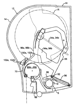
. A sensor is provided in the dispensing apparatus 10 for sensing the
diameter of the stub roll S and for controlling the pivoting of the nipping
element 70 in response to sensing a predetermined diameter for the stub roll
S. The sensor preferably includes a contact element 86 and camming
element 88 pivotally mounted in the rear casing 16, as shown in Figs. 16-20.
The contact element 86 is pivotally connected to the bottom rear interior
surface of the rear casing 16. As sheet material is dispensed from a stub roll
S in the rear casing 16, the contact element 86 pivots counterclockwise, as
shown in the views of Figs. 16-20, from a first position shown in Fig. 18 to a
second position shown in Figs. 16, 17, and 20. During this pivoting, a lower
contacting surface of the contact element 86 contacts the outer
circumferential surface of the stub roll S.
The camming element 88 is pivotally connected to a rear wall of the
rear casing 14. As shown in Figs. 16-20, a projection pin 92 extends from the
camming element 88 into an elongated slot 90 in the contact element 86 to
19
CA 02260632 2007-09-11
couple pivotal movement of the contact element 86 and the camming element
88. As the sheet material is dispensed from the stub roll S, the camming
element 88 pivots ctockwise, as shown in the views of Figs. 16-20, from a
first
position shown in Fig. 18 to a second position shown in Figs. 16, 17, and 20.
During this pivoting, the projection pin 92 moves along the length of the slot
90.
Preferably, one or more biasing eiements.116, such as torsion springs,
are provided at the pivot point of the camming element 88 to bias the
camming element 88 rotafionatly In the clockwise direction as shown in Figs.
16-20. Because the movement of the camming element 88 and contact
element 86 are linked to one another, the biasing elements. 916 also bias the
contact element 86 toward the stub roll S in the rear housing 16. This
ensures that the lower contacting surface of the contact element 86 remains
in contact with the stub roll S to track the diameter of the stub roll S as
sheet
material is dispensed therefrom. The biasing of the contact element 86
against the stub roll S also provides a force that maintains the stub roll S
between the contact element 86 and ribs 32, shown in Figs. 6 and 7, in the
rear casing 16 without allowing the stub roil S to translate upwards toward
the
dispensing rollers 44a-44d throughout the dispensing of sheet material from
the stub roll S. In addition, the biasing of the contact element 86 against
the
stub roll S limits free rotation of the stub roll S throughout the dispensing
from
the stub roll S. To Iimit free rotation of the stub rofl S even more, the
contact
element 86 also may indude ribs (not shown) to increase friction between the
stub roll S and the contact element 86.
As shown in Figs. 3a, 3b and 7, the camming element 88 includes a pair
of arms 94a and 94b spaced apart so that the tensioning elements 36a and 36b
are positioned therebetween. The arms 94a and 94b include tabs 96a and 96b,
respectively. When the front cover 14 is open, the tabs 96a and 96b may be
pressed by a user to pivot the camming element 88 and contact element 86
away from the 'stub roll compartment of the rear housing 16, as shown in
Figs. 6 and 7. This allows for insertion of a stub roll into the stub roll
compartment of the rear casing 16. In addition, the movement of the
CA 02260632 2007-09-11
camming element 88 and contact element 86 allows for removal of a core D
of a stub roll (see Figs. 16 and 17) after pivoting the lever 66 away from the
rear casing 16, as shown in Fig. 6.
As shown in Figs. 3a, 3b and 7, cam surfaces 98a and 98b are provided
on the front of the arms 94a and 94b to control pivoting of the nipping
element
70. Cam followers 100a and 100b, shown in Figs. 4 and 13-15, extend from
opposite ends of the nipping element 70 and contact the cam surfaces 98a and
98b during dispensing of sheet material from the stub roll S. To maintain the
contact between the cam followers 100a and 100b and the cam surfaces 98a
and 98b, the biasing elements 80a and 80b and. 82a and 82b, shown in Fig.
13, bias the cam followers 100a and 100b toward the cam surfaces 98a and
98b.
As shown in Figs. 18 and 19, when the sheet materiai is dispensed
from the stub roll S, the cam surfaces 98a and 98b slide with respect to the
cam followers 100a and 100b away from the rollers 44a-44d while the arms
94a and 94b pivot in the clockwise direction. When almost all of the sheet
materiai is removed from the stub roll S, as shown in Fig. 20, the cam
surfaces 98a and 98b slide past the cam followers 100a and 100b. This
places the cam foiiowers 100a and 100b out of engagement with the cam
surfaces 98a and 98b and thereby allows the biasing elements 80a and 80b,
shown in Fig.13, to bias the nipping element 70 pivotaify toward the
dispensing rollers 44a-44d, as shown in Figs. 16 and 17.
Prior to pivoting of the nipping element 70, the guides 64a and
64b extending from the L-shaped bearing clips 63a and 63b, shown in Figs. 3b,
8, and 9, align an end portion of sheet material from the reserve
roll between the nipping element 70 and stub roll sheet material contacting
the
dispensing rollers 44a-44d. Preferably, the cam surfaces 98a and 98b,
shown in Figs. 3a, 3b, and 7, are shaped so that the pivoting of the
nipping element 70 toward the rollers 44a-44d occurs just prior to
when all of the sheet material is removed from the stub roll S. When
the nipping element 70 pivots toward the rollers 44a-44d into the
position shown in Fig. 20, the upper portion of the nipping element 70
places the end portion of sheet material from the reserve roll R in
21
CA 02260632 2007-09-11
a nip formed between the nipping element and rollers 44a-44d. Continued
dispensing of material from the stub roll S causes rotation of the rollers 44a-
44d to also dispense the sheet material of the reserve roll R from the outlet
38, as shown in Fig. 20.
The dispensing apparatus 10 also preferably includes structure for
limiting contact of the reserve roll R with the outer surface of the rollers
44a-
44d and stub roll sheet material on the rollers 44a-44d during dispensing of
sheet material from the stub roll S, as shown in Figs. 18-20. As shown in
Figs.
3a and 13-15, isolating elements 102a and 102b are pivotally coupled to the
mounting plate 72 attached to the inside of the front cover 14. The isolating
elements 102a and 102b include respective side slots 104a and 104b, shown
in Fig. 13, for controlling pivoting of the isolating elements 102a and 102b.
Projection pins 106a and 106b extending from a top portion of nipping
element 70 move in the slots 104a and 104b, respectively, during pivoting of
the nipping element 70 to control movement of the isolating elements 102a
and 102b. The slots 104a and 104b are shaped so that the top end portions
of the isolating elements 102a and 102b move upwards in the housing 12
above a top surface of the nipping element 70 when the nipping element 70
pivots away from the rollers 44a-44d, as shown in Figs. 18 and 19. In this
position, the isolating elements 102a and 102b lift the reserve roll R above
the
outer surface of the dispensing rollers 44a-44d so that the reserve roll R
does
not rotate along with dispensing rollers 44a-44d during dispensing of the stub
roll sheet material.
When the nipping element 70 pivots toward the dispensing rollers 44a-
44d, as shown In Fig. 20, the projection pins 106a and 106b, shown in Fig.
13, slide in the slots 104a and 104b, and the top end portions of the
isolating
elements 102a and 102b move downwards in the housing 12 approximately
level with a top surface of the nipping element 70. In this position, shown in
Figs. 16, 17, and 20, the reserve roll R is placed on stub roll sheet material
covering the dispensing rollers 44a-44d so that the reserve roll R and rollers
44a-44d rotate together. Because the isolating elements 102a and 102b
22
CA 02260632 2007-09-11
extend and retract in response'to pivoting of the nipping element 70, the
pivotal movement of the contact element 86 and camming element 88 and
movement of the camming surfaces 98a and 98b control the movement of the
isolating elements 102a and 102b.
During placement of the reserve II R on the rollers 44a-44d, the guides
37a and 37b, shown in Figs. 3a, 3b and 7, guide the sheet material of the
reserve roll R to limit lateral sheet material tracking in the dispenser 10.
In
addition, the friction bands 50a, 50b, 50c, and 50d, shown in Figs. 8 and 9,
on
respective rollers 44a, 44b, 44c, and 44d increase friction between the
reserve
roll R and the rollers 44a-44d.
As shown in Figs. 21-23, a movable reserve roll diameter sensor 108
and indicator 110 are provided for respectively monitoring the diameter of the
reserve roll R and providing an indication when the reserve roll R is a
predetermined diameter. The indicator 110 extends from the roll diameter
sensor 108 and includes a projection 118 placed in a slot 112 (see Figs. 13
and 21-23) formed in the mounting plate 72 for controlling movement of the
indicator 110. As shown in Figs. 21-23, the roll diameter sensor 108 has a
surface for contacting the reserve roll R during dispensing of sheet material
from the reserve roll R. When sheet material is removed from the reserve roll
R, the roll diameter sensor 108 pivots due to gravity toward the reserve roll
R
and thereby pivots the projection 118 in the slot 112.
As shown in Figs. 3a and 4, a bottom portion of the front cover 14
includes an indicator opening 114. When the reserve roll R is a predetermined
diameter, the indicator 110 and projection 118 pivot so that the slot 112
allows
a portion of the indicator 110 to drop through the indicator opening 114, as
shown in Fig. 22.
As shown in Figs. 16-23, the interior section of the housing 12 for
accommodating the stub roll S is smaller than the interior section of the
housing 12 for accommodating the reserve roll R. Preferably, the slot 112,
shown in Figs. 13 and 21-23, is shaped so that the portion of the indicator
110 drops through the indicator opening 114 when the diameter of the
reserve roll R is small enough to place the reserve roll R in the stub roll
23
CA 02260632 2007-09-11
compartment of the housing 1 In other words, the indicator 110 provides a
discrete, visual indication of when the reserve roll R will fit and can be
placed
in the stub roll compartment and a new reserve roll can be loaded in the
housing 12. The indicator 110 differs from conventional sheet material
dispensers including a display proportional to the diminishing diameter of a
product roll, because these conventional displays do not indicate a definitive
time when the reserve roll will fit in the stub roll compartment, but rather
leave
the decision about whether a new roll of material can be loaded up to the
subjective discretion of an operator person. Thus, the present invention
reduces problems associated with premature opening of the cabinet by
inexperienced operators.
The indicator 110 extends from the indicator opening 114 until the front
cover 14 is opened and a new reserve roll R is loaded in the housing 12.
Opening the front cover 14 moves the indicator 110 in the housing 12 via the
opening 114, as shown in Fig. 22, and resets the indicator 110 for sensing the
diameter of the new reserve roll R.
Methods of dispensing sheet material from at least one roll of sheet
material are discussed below with reference to Figs. 1, 2, 3a, 3b and 4 to 23.
The roll of sheet material includes a plurality of individual sheets separated
by
perforation tear lines including frangible perforation bonds and perforations.
Although the invention is described in connection with the structure shown in
Figs. 1, 2, 3a, 3b, and 4 to 23, and in connection with the dispensing of
sheet
material having perforation tear lines including uniform frangible perforation
bonds and perforations, it should be understood that the invention in its
broadest sense is not so limited.
To load the dispensing apparatus 10 initially with sheet material, an
operator moves the front cover 14 to the open position, as shown in Fig. 3a,
so
that the nipping element 70 moves away from the rollers 44a-44d to open the
nip. The operator then mounts a roll of sheet material R in the mounts 35a and
35b on the arms 34a and 34b, as shown in Fig. 4, and allows the roll of sheet
material R to rest on the surface of the rollers 44a-44d. While the cover 14
is
still in the open position, the operator extends a tail end portion of sheet
material from the reserve roll R and passes this tail end portion along the
24
CA 02260632 2007-09-11
surface of the rollers 44a-44d, between the rollers 44a and 44d and the
guides 64a and 64b, and through the dispensing outlet 38.
Then, the operator pivots the front cover 14 to the closed position
shown in Figs. 1 and 2. When the front cover 14 is closed, upper and lower
portions of the nipping element 70 form a nip for passage of the sheet
material
between the nipping element 70 and the outer nipping surface of the rollers
44a-44d, as shown in Fig. 16, and the biasing elements 80a, 80b, 82a, and
82b, shown in Fig. 13, bias the nipping element 70 toward the rollers 44a-44d.
The nip, friction bands 50a, 50b, 50c, and 50d shown in Figs. 8 and 9, and
tensioning elements 36a and 36b shown in Figs. 3a, 3b and 7, apply frictional
braking forces on the sheet material to limit free rotation of the sheet
material
roll R and to restrain lateral translation of the sheet material relative to
the
rollers 44a-44d during dispensing of the sheet material through the
dispensing outlet 38.
When a user pulls the end portion of sheet material extending from the
dispensing outlet 38, the roll of sheet material rotates and tension induced
in
the sheet material is concentrated at the edges of the sheet material by the
narrowed dispensing outlet 38 initiating separation at the perforation tear
line
from one or both edges. Continued pulling of the end portion of sheet material
propagates the perforation separation across the sheet from the edges toward
the center to dispense a single sheet, as shown in Fig. 2. During pulling of
the
sheet material the rollers 44a-44d, shown in Figs. 3a, 4, and 7-9, and the
sheet
material roll R rotate in the housing 12.
If the end portion of sheet material does not extend a sufficient
distance out from the dispensing outlet 38, a user may depress the lever 66,
as shown in Fig. 5, while the front cover 14 is maintained in the closed
position. Actuating the lever 66 rotates the rollers 44a-44d and thereby
passes sheet materiai in the nip out from the dispensing outlet 38.
As the diameter of the roll R of sheet material is reduced, the roll
diameter sensor 108 mon'rtors the diameter of the roll R and, when the
diameter of the roll R is small enough to place the roll R in the stub roll
oompartment of the rear casing 16, a portion of the indicator 110 extends
CA 02260632 2007-09-11
from the housing 12, as showri in Fig. 22. This provides a visual indication
of
the need to place a new reserve roll in the housing 12.
To load a new reserve roll of sheet material in the apparatus 10, the
operator pivots the front cover 14 to the open position shown in Figs. 3a and
23. When the front cover 14 is opened, the indicator 110 moves in the housing
12 via the opening 114, as shown in Fig. 23, so that the indicator 110 and
roll
diameter sensor 108 are reset to the position shown in Fig. 21 upon loading of
the new reserve roll and closing of the front cover 12.
Opening the front cover 12 also moves the nipping element 70 away
from the rollers 44a-44d to remove the sheet material nip. If a core D, shown
in
Figs. 16 and 17, of a previously expired stub roll is present in the stub roll
compartment of the rear casing 16, one or both of the tabs 96a and 96b,
shown in Figs. 3a, 3b and 7, are pressed to pivot the contact element 86 away
from the core D, and the lever 66 is pivoted up and away from the rear casing
16, as shown in Fig. 6. The core D is then passed under the rollers 44a-44d
and between ribs 32, to remove it from the rear casing 16.
To move the partially consumed reserve roll R to the stub roll
compartment of the rear casing 16, the operator presses one or both of the
tabs 96a and 96b shown in Figs. 3a, 3b and 7 to pivot the camming element
88 and contact element 86 away from the stub roll compartment, as shown in
Figs. 6 and 7. The operator then removes the partially consumed reserve roll R
shown in Fig. 17 from the mounts 35a and 35b and moves this roll into the
stub roll compartment of the rear casing 16 to act as a stub roll S, as shown
in
Fig. 18. When the stub roll S is moved into the stub roll compartment, the end
portion of sheet material extending from the stub roll S remains on the
exterior
surface of the rollers 44a-44d and continues to extend from the dispensing
outlet 38. Releasing the pressure applied to the tabs 96a and 96b allows the
biasing elements 116 to bias the contact element to 86 against the outer
surface of the stub roll S, as shown in Fig. 18.
The operator then places a new reserve roll R in the mounts 35a and
35b and passes a relatively short end portion of sheet material from the
reserve roll R between the guides 64a and 64b shown in Figs. 3a and 4 and
26
CA 02260632 1999-01-29
the end portion of stub roll sheet material passing on the outer surface of
the
rollers 44a-44d. When the front cover 14 is pivoted to the closed position, as
shown in Fig. 18, the cam followers 100a and 100b contact the respective
cam surfaces 98a and 98b on the arms 94a and 94b. This pivots the upper
portion of the nipping element 70 away from the rollers 44a-44b to prevent
nipping of the end portion of sheet material extending from the reserve roll
R.
The pivoted position of the nipping element 70, shown in Fig. 18, also extends
the isolating elements 102a and 102b above a top surface of the nipping
element 70. This causes the isolating elements 102a and 102b to lift the
reserve roll R away from the outer surface of the rollers 44a-44d and thereby
limits contact between the reserve roll R and the rollers 44a-44d and between
the reserve roll R and stub roll sheet material on the rollers 44a-44d.
As shown in Fig. 18, a lower portion of the nipping element 70 and the
outer nipping surface of the rollers 44a-44d form a nip for the end portion of
sheet material from the stub roll S only. The sheet material is dispensed from
the stub roll S in the same way in which sheet material was dispensed from
the reserve roll R - by pulling the end portion of sheet material extending
from
the dispensing outlet 38, or by pressing the lever 66 to rotate the rollers
44a-
44d. As the diameter of the stub roll S is reduced, the contact element 86 is
biased against the outer surface of the stub roll S and pivots toward the stub
roll S, as shown in Figs. 19 and 20. The biasing of the contact element
restricts free rotation of the sub roll S and prevents upward movement of the
stub roll S in the casing 16 throughout dispensing from the sub roll S. The
pivoting of the contact element 86 causes the camming element 88 to pivot in
a counter clockwise direction, as shown in the views of Figs. 19 and 20,
thereby moving the cam surfaces 98a and 98b with respect to the cam
followers 100a and 100b.
When almost all of the sheet material is dispensed from the stub roll
S, the cam surfaces 98a and 98b move past the cam followers 100a and
100b and place the cam followers 100a and 100b out of contact with the cam
surfaces 98a and 98b, as shown in Fig. 20. The biasing of the biasing
elements 80a and 80b shown in Fig. 13 pivots the upper portion of the
27
CA 02260632 1999-01-29
nipping element 70 toward the'rollers 44a-44d, as shown in Fig. 20, to place
the end portion of sheet material from the reserve roll R in the nip between
the nipping element 70 and the outer nipping surface of the rollers 44a-44d.
The pivoting of the nipping element 70 also causes the isolating elements
102a and 102b to retract and lower the reserve roll R into contact with the
end
portion of stub roll sheet material passing on the outer circumferential
surface
of the rollers 44a-44d.
When the nipping element 70 initially pivots toward the rollers 44a-44d,
end portions of sheet material from both the reserve roll R and the stub roll
S
are placed in the nip, as shown in Fig. 20. When a user pulls the remaining
sheets from the stub roll or actuates the lever 66 to dispense sheet material
of the stub roll, the rollers 44a-44d rotate and feed the sheet material of
the
reserve roll R through the nip and out from the dispensing aperture 38 along
with the last few sheets from the stub roll. Sheet material is then dispensed
from the reserve roll R in the same manner as described above in connection
with the initial roll R.
The dispenser of the present invention holds a high capacity of sheet
material in a compact space. The capacity of a dispenser is important to the
purchasers of such systems since the capacity is directly related to costs
associated with refilling the dispenser with sheet material. Purchasers of
sheet material dispensing systems are also concerned with the space that the
sheet material dispenser occupies when in use, i.e., the wall space. The
space that a dispenser occupies can be expressed in a variety of ways. One
way is by the total volume that the dispenser occupies. Another way is by the
projected area of the sheet material dispenser against the mounting surface
9, i.e., the wall area. Yet another way is by the area of the profile of the
side
of the dispenser, i.e., the profile area. A "capacity efficient" sheet
material
dispenser is one which maximizes the ratio of the sheet material volume
(capacity) to the total enclosed dispenser volume. One way of evaluating the
"capacity efficiency" is by calculating the ratio of the sheet material volume
(capacity) to the projected area of the dispenser on the mounting surface.
Another way of evaluating the "capacity efficiency" is by calculating the
ratio
28
CA 02260632 1999-01-29
of the sheet material volume (capacity) to the profile area of the side of the
dispenser. In effect the maximum amount of sheet material in the smallest
amount of space is the ideal.
For a touchless sheet material dispenser wherein a roll of sheet
material having a width of at least about 5 inches is rotatably mounted in the
interior and whose interior further includes at least a first portion for a
stub roll
of sheet material and at least a second portion for a reserve roll of sheet
material, the value for the ratio of the maximum sheet material volume (in
roll
form) to the total enclosed volume of the dispenser is preferably at least
about 35%, more preferably at least about 40%, and most preferably at least
about 45%.
For a touchless sheet material dispenser wherein a roll of sheet
material having a width of at least about 5 inches is rotatably mounted in the
interior and whose interior further includes at least a first portion for a
stub roll
of sheet material and at least a second portion for a reserve roll of sheet
material, the value for the ratio of the maximum sheet material volume (in
roll
form) expressed in cubic inches to the projected area of the dispenser on the
mounting surface expressed in square inches is preferably at least about 3.0
cubic inches/square inch, more preferably at least about 3.1 cubic
inches/square inch, and most preferably at least about 3.2 cubic
inches/square inch.
For a touchiess sheet material dispenser wherein a roll of sheet
material having a width of at least about 5 inches is rotatably mounted in the
interior and whose interior further includes at least a first portion for a
stub roll
of sheet material and at least a second portion for a reserve roll of sheet
material, the value for the ratio of the maximum sheet material volume (in
roll
form) expressed in cubic inches to the side profile area of the dispenser
expressed in square inches is preferably at least about 4.5 cubic
inches/square inch, more preferably at least about 5.0 cubic inches/square
inch, and most preferably at least about 5.5 cubic inches/square inch.
In a majority of the areas where sheet material dispensers are typically
used, dispensers that produce a low sound level are preferable, particularly
in
29
CA 02260632 2007-09-11
health care facilities and offce'buildings. The sound level produced by the
sheet material dispenser can be magnified depending on the mounting
surface material and construction and dispensing environment. Therefore, it
is desirable to have a sheet material dispenser that minimizes the sound
produced when it is used to dispense sheet material. Known sheet material
dispensers were compared to the sheet material dispenser of the present
invention to determine the level of sound generated when a segrnent of sheet
material was dispensed from the dispensers. The sound was measured in
decibels (dBA).
The apparatus as shown in Fig. 25 illustrates the testing conditions
used to measure the sound level in Examples 1 and 2. Each sheet material
dispenser was securely mounted to a portable stand 200 constructed of 3/4"
thick plywood. The test was performed in a soundproof enclosure manufactured
by: Industrial Acoustics Co., Bronx, NY, Model IC 250 Mini Booth. A
Permissible
Noise Dosimeter manufactured by Quest Electronics, Model Micro-14 was used
to record the maximum sound level detected during each dispense. The
dosimeter 210 was placed five inches from the center of the dispenser outlet.
Ten readings were taken and averaged for each dispenser. A similar type of
sheet material was dispensed from each dispenser within a given example.
The sheet material dispenser of the present invention produces a
maximum sound level preferably less than about 81 dBA, more preferably
less than about 79 dBA, and most preferably less than about 76 dBA, when
dispensing sheet material therefrom.
CA 02260632 1999-01-29
EXAMPLE 1
Dispense Roll Towel Dispenser, Readings in dBA
Number A B 1
1 84.7 84.3 72.7
2 88.5 84.3 77.6
3 85.5 86.2 75.3
4 82.5 85.5 75.3
87.7 84.3 75.7
6 85.1 87.3 78.3
7 87.0 85.5 76.5
8 87.0 82.8 77.6
9 88.5 82.1 75.3
87.0 85.5 76.5
Ave. 86.4 84.8 76.1
Std. Dev. 1.89 1.55 1.60
Example 1 illustrates a comparison of the compilation of test results of the
recorded maximum sound level of individual towel dispenses from different
dispensers in a controlled acoustical environment. Comparative Dispensers
A and B are counter rotating cut off roll type dispensers. Non-perforated
white paper roll toweling was dispensed from Dispensers A and B. Dispenser
1 is a dispenser according to the present invention. Perforated white paper
roll toweling was dispensed from Dispenser 1.
31
CA 02260632 1999-01-29
EXAMPLES 2 and 3
Dispense Readings in dBA
Number 2 3
1 81.3 79.1
2 80.6 71.6
3 82.5 78.7
4 81.7 74.6
81.7 71.6
6 78.7 77.6
7 80.6 75.7
8 81.3 79.1
9 83.2 75.7
81.3 75.7
Ave. 81.3 75.9
Std. Dev. 1.20 2.78
Examples 2 and 3 illustrate a compilation of test results of the recorded
maximum sound level of individual towel dispenses in a controlled acoustical
environment. Examples 2 and 3 were performed with Dispenser 1 of
Example 1. The same perforated white paper roll toweling used in Dispenser
1 of Example 1 was dispensed from Dispenser 1 in Example 3. Brown
perforated paper roll toweling having a higher tensile modulus than the white
paper toweling used in Dispenser 1 was dispensed from Dispenser 1 in
Example 2.
32
CA 02260632 1999-01-29
EXAMPLE 4
Dispenser 1 Dispenser C Dispenser D Dispenser
E
msmv/tev 42.8% 32.1% 27.8% 27.1%
v/pa 3.2 2.9 2.2 2.1
v/spa 5.7 4.1 3.4 3.3
The capacity efficiency of Dispenser I according to the present invention and
Comparative Dispensers C, D and E was calculated. Comparative Dispenser
C is a counter rotating cut off roll type dispenser with calculations
approximating the addition of a stub roll. Comparative Dispensers D and E
are counter rotating cut off roll type dispensers. The msmv/tev is the
maximum sheet material volume per total enclosed volume expressed as a
percentage. The v/pa is the ratio of maximum sheet material volume to
projected area expressed as cubic inches/square inches. The v/spa is the
ratio of maximum sheet material volume to side profile area expressed as
cubic inches/square inches.
It will be apparent to those skilled in the art that various modifications
and variations can be made to the structure and methodology of the present
invention without departing from the scope or spirit of the invention. In view
of
the foregoing, it is intended that the present invention cover modifications
and
variations of this invention provided they fall within the scope of the
following
claims and their equivalents.
33