Language selection

Search

Patent 2260693 Summary

Third-party information liability

Some of the information on this Web page has been provided by external sources. The Government of Canada is not responsible for the accuracy, reliability or currency of the information supplied by external sources. Users wishing to rely upon this information should consult directly with the source of the information. Content provided by external sources is not subject to official languages, privacy and accessibility requirements.

Claims and Abstract availability

Any discrepancies in the text and image of the Claims and Abstract are due to differing posting times. Text of the Claims and Abstract are posted:

  • At the time the application is open to public inspection;
  • At the time of issue of the patent (grant).
(12) Patent: (11) CA 2260693
(54) English Title: FIXING DEVICE USING COMPRESSED GAS
(54) French Title: DISPOSITIF DE FIXATION UTILISANT LE GAZ COMPRIME
Status: Term Expired - Post Grant Beyond Limit
Bibliographic Data
(51) International Patent Classification (IPC):
  • B25C 1/10 (2006.01)
  • B25C 1/08 (2006.01)
(72) Inventors :
  • NAYRAC, FREDERIC (France)
  • JAILLET, GUY (France)
  • TOULOUSE, BRUNO (France)
(73) Owners :
  • SOCIETE DE PROSPECTION ET D'INVENTIONS TECHNIQUES S.P.I.T.
(71) Applicants :
  • SOCIETE DE PROSPECTION ET D'INVENTIONS TECHNIQUES S.P.I.T. (France)
(74) Agent: FINLAYSON & SINGLEHURST
(74) Associate agent:
(45) Issued: 2000-11-21
(22) Filed Date: 1999-02-05
(41) Open to Public Inspection: 1999-08-13
Examination requested: 1998-02-05
Availability of licence: N/A
Dedicated to the Public: N/A
(25) Language of filing: English

Patent Cooperation Treaty (PCT): No

(30) Application Priority Data:
Application No. Country/Territory Date
98 01748 (France) 1998-02-13

Abstracts

English Abstract

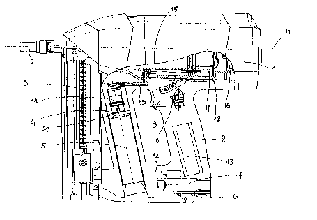
Fixing device using compressed gas, comprising a casing (1) containing a combustion chamber (17), a housing (4) for receiving a cartridge of compressed gas (5), a duct (19) for injecting compressed gas into the combustion chamber (17) from the cartridge (5), a magazine (3) for supplying fixing elements, a housing (6) for receiving a battery (7) for supplying electricity and a handle (8) connected directly to the casing (1) and substantially perpendicular to an axis (11) of the casing (1). The housing (4) for receiving the cartridge (5) extends substantially parallel to the handle (8) and is offset with respect thereto along the axis (11) of the casing (1).


French Abstract

Dispositif de fixation utilisant du gaz comprimé, comprenant un caisson (1) contenant une chambre de combustion (17), un boîtier (4) logeant une cartouche de gaz comprimé (5), un conduit (19) injectant du gaz comprimé dans la chambre de combustion (17) depuis la cartouche (5), un magasin (3) fournissant des éléments de fixation, un boîtier (6) logeant une batterie (7) fournissant de l'électricité, et une poignée (8) reliée directement au caisson (1) et essentiellement perpendiculaire à un axe (11) du caisson (1). Le boîtier (4) logeant la cartouche (5) s'étend essentiellement parallèlement à la poignée (8) et est décalé par rapport à celle-ci le long de l'axe (11) du caisson (1).

Claims

Note: Claims are shown in the official language in which they were submitted.

5
WHAT IS CLAIMED IS:
1. Fixing device using compressed gas, comprising a casing (1) containing a
combustion chamber (17). a housing (4) for receiving a cartridge of compressed
gas (5), means (19) for injecting compressed gas into the combustion chamber
(17) from the cartridge (5), a magazine (3) for supplying fixing elements, a
housing (6) for receiving means (7) for supplying electricity and a handle (8)
connected directly to the casing (1) and substantially perpendicular to an
axis
(11) of the casing (1), characterised in that the housing (4) for receiving
the
cartridge (5) extends substantially parallel to the handle (8) and is offset
with
respect thereto along the axis (11) of the casing (1).
2. Device according to claim 1, wherein the housing (4) for receiving the
cartridge (5) is disposed between the handle (8) and the magazine (3) for
supplying fixing elements.
3. Device according to claim 1, wherein a bridge (12) is provided to house
means (7) for supplying electricity, connecting the housing (4), for receiving
the
cartridge (5), and the handle (8).
4. Device according to claim 3, wherein the bridge (12) for housing the means
(7) for supplying electricity connects the respective ends of the housing (4),
for
receiving the cartridge (5), and the handle (8), opposite to their ends which
are
connected to the casing (1).
5. Device according to claim 1, wherein the means (19) for injecting
compressed gas enter substantially in the middle of the combustion chamber
(17).
6. Device according to claim 1, wherein a solenoid valve (14) is provided for
metering compressed gas, extending along an axis (20) as an extension of which
the compressed gas cartridge (5) is intended to extend.

Description

Note: Descriptions are shown in the official language in which they were submitted.


io3 au»~~ a 'a~pu~ea ay ~:uo.~ laq~r.~a uor~snqmoo a~ o~m seD passaiduroa
°uraaaCui Toy
sm~~u 'a~i>riuca seD passasdmoa E ~~aaa~ zog ~msno~ a 'zaqamilo uo~snqmoa a
~muT~luoo
~niseo ~ ~u~sudmoa sED passazdzaoa 'utsn aauap Ding E o; saa~ai Bor~nanm aq1
pna sy~ o,~
-~uzo d aauep;d Ieapi
s~ o~ ~aso~o aaznap ~u~~ a~~o W nEr~~o a~i~aa a~ .~uuq o~ ~~nos sn~ s~r~
~.~or~dd~ ate,
-~a~ xapur stq sa~dde zo~szado a~ ~a~M o~
aTp~~ a~ uo ~uiod a ~e ~C~er~aeasqt~s panoursod aq Plno~s ~rn.E~~o ar.~u3o sy
paou~~~q aq o~
anoqe paBgap ad~i a~~o aoinap ~ jog .~apao ul 'uoT~50d Duu~ ate m ~
~nrsrGtq~~s pue aouap
a~ ~~p~eu rri s2t~~no~ip saauauadaa 'ptre~ ano ~ alpae~ ~BUg a~ 4uiddu~ ~d
aouap
a~~ ~ ii~plo i~ ua i~r~ vo~~.ia do u~ ~~ os paouele q ~Iao o d ~nmaaa~ am
saolnap ~u~cg asa~,
'aIP~~I
~aug a~ aprstcr pasno~ st anptn~o Ia~y aq~ saomap .~a~o za s~aiar~nn 'alp~retl
a~ p~ Dmcsea
a~ uaanuaq '~ut5~a a~,~o sixe a~ o~ Ia~ered spma~xa Dmsno~ aDpp~o a~ saornap
ureuao u1
'amze.~~u
~nTd a~ buoy 'aue;Ea arp~o sore a~ o~ ielriarpBadrad ~C~sr~u~~qns spua~a
~~eiauaD
Dmcsnor~ ~a~~q aid, vaiseo aid o~ pazaauuoo Wuaa alpue~ a~ pwe 'apm~ anjd a~
ynn
~uz~~arrnmzuroo aurLeDeaa a~ 'see s~ anole ra~qxo r~aea o~ ~aadsai r~pnn ~as~o
aie pue Dmsea
a~~o sLx~ a~~ o~ ~re~n:~rpnadrad fi~~~~u~~.sqns pua~.ta aipueq ~uu~ a~ pue
a~eDecu pnld a~x
~aomap aouroW u-e~o su~aii~ ~q ~aqu~~ua aousnqtuoo
a~ u~ pam~'~noo sea no~asnq~oa a~q~~o uoiso~dxa ~u~o.uuoa ion .ca~~u~ a
palunouc 5T rio~~,
uo aTp~ W cug E pae f~a~sq E Duv~aaa so3 ~rsno~ g 'sDnTd,~o aBrzeaeru ~
'~cns~ea aq~3o
~uo~ aq.~ ~E .~m~aaCo.~d aprr~ Dntd a 'iaqureqo uonsns~uoo aft oztu se°
passaiduioo Dtrr~oaCm sod
~onp ~ autn~e~ 'sea passaldmoo~o aDpuu~eo a ~uinzaoal ion nuisnorj ~ '~aqrumlo
uopsnqzaoo ~
~amrelBOO ~~ea a ~msudiuoo 'seD passaxdm~oo aro~sn aauap ~n~~ a o~ sa~e~a~
uoauanm a~
s~~ a~ss~~oa ~~sn ~~~~a ~~x~x
SO-ZO-666l ~6909ZZ0 ~a

CA 02260693 1999-02-OS
supplying fi.~dng elements, a hou~g for receiving means for supplying
eJ.ectriciry and a handle
directly connected to the casing and substantially perpendicular to an ate, of
the casing,
characterised in that the cartridge housing e~-tends substamially parallel to
the handle and is
offset with respect tliereto along the ass of the casing.
This type ofrelztzve arrangement ofthe camidge housing and the handle oilers a
better
distribution of the weight of the various elements of the device.
Tlie camidge housing is preferably disposed betwEen the handle and the
magazine for
supplying fi,~ng elements.
In a preferred embodiment, a bridge for housing the means for supplying
electricity is
provided, connecting the cartridge housing and the handle.
The housing for receiving the means for supplying electricity no longer being
connected to the
maga~ne of fia~ing elements, tire device is still supplied electrically wh en
th a magazine is
removed.
The applicant leas also managed to exploit the generally considerable weight
of tine means for
supplying electricity in order to balance the device still further.
The invention wldl be better understood with the aid ofthe following
descriptiozt of a particular
embodiment ofthe fi.~ng deuce of the invez~tzon with reference to the attached
drawing in
which.
- Figure 1 Illustrates a lateral view of tl~e fi.~dng device, and
- Fgure 2 ~lustrates a partial lateral cross-sectional view ofthe device ofthe
figure.
The fi.~ng device ofthe invention is intended to fix fi.~dug elements, in this
case plugs, into a
fining support, a concrete wall, for example, by explosion of compressed gas.
2

CA 02260693 1999-02-OS
Tlie device essentially comprises a casing 1, a plug guide 2 prvjec.'ting out
of the from of the
casing 1, a magazine 3 for supplying plugs, a housing 4 for receiving a
caz'tridge of
compressed gas ~, a housing 6 for receiving a battery 7 for supplying
electricity to the device,
and a handle 8. 'fhe casing I and the plug guide 2 both have an axis 11.
The casing 1 contaitzs a cylinder 15 in which is mounted a plug propellaig
piston, a rear
cylinder vend 16. a combustion chamber 17 and a combustion chamber sleeve 18.
The housing 4 also contains a solez~oi.d valve 1 ~. for metering gas injected
into the combustion
chamber 17, intended to receive an injection join~ag piece for the compressed
gas cartridge ~.
.T..b.e solenoid vatve 1.4 extends along an axis 20 as an e~-iension of
wliicli the con~ressed aas
cartridge 5 is intended to extend after introduction into the housing 4. A
duct 19 for injectlag
compressed gas izzto the coxubusd.on chamber I7 from the camidge 5 connects
the solenoid
valve I4 to the combustion chamber I7 and in this case enters substantially in
the middle of
the combustion chamber 17 along the axis 11.
fhe handle S has a trigger 9 provided to actuate a switch 10 for controlling
an. igniti.ou device
intended to explode the compxeseed gas con~taimed in the combustion chamber
17.
An electronic module 13 for controlling the electronics of the device, and in
particular the
solenoid valve 14 and the i~ition device, is housed inside the handle 8.
The h ap.dle 8, the housing 4 for receivin' the cartridge 5, and the magazine
of plugs 3 extend
in a common plane P containing the axis 1 i, on the same side of the axis 11
in this plane P,
sub stantially p erp endicul ar to th a axis 1 I . Th a la an dle 8 and the
housing 4 fox the cartridge S
are directly connected at one of their ends to the casing 1. The three
elements 8, 4, 5 are thus
substantially parallel to each other. It should be emphasized that the camidge
5, introduced
into its housing 4, extends sub ~antralLy parallel to the handle 3.
The handle 8 is in tliis case co~ected substantially to the middle of the
casing 1, along the axis
11, and the magazuae 3 communicates with the plug guide 2, the ma'azine 3 thus
being offset
3

CA 02260693 1999-02-OS
forwards with respect to the h~dle 8 along the alas l 1. The housing 4 for
receiving the
cartridge 5 i.s also offset forwards with respect to the liandle 8 and is
disposed between the
magazine 3 and the handle 8 along the a.Yis l I.
.4 bridge l? for housing the battery 7, and in which the hoasung 6 for
zeceiving the battery 7 is
arranged, conneWs the respective ends ofthe housing 4, for receiving the
cartridge 5, and the
handle 8 opposite to their ends which are connected to the casing 1. 'floe
bridge 12 and the
battery 7, placed in its housing 6, extend ymbstantially parallel to the axis
11.
Sy reason of the arrangement of the housing 4 for the cartridge 5, of the
bridge 12 for housing
the battery 7, of the handle 8 and of the pluD zvagazine 3 the centre of gz-
avity of the device is
substantially at an ideal point ofbalance which is that an which an operator
places .bis index
finger when holding the device in one hand by means of the handle iz~ order to
f re~ This ideal
point is substantially at the trigger 9.
4

Representative Drawing
A single figure which represents the drawing illustrating the invention.
Administrative Status

2024-08-01:As part of the Next Generation Patents (NGP) transition, the Canadian Patents Database (CPD) now contains a more detailed Event History, which replicates the Event Log of our new back-office solution.

Please note that "Inactive:" events refers to events no longer in use in our new back-office solution.

For a clearer understanding of the status of the application/patent presented on this page, the site Disclaimer , as well as the definitions for Patent , Event History , Maintenance Fee  and Payment History  should be consulted.

Event History

Description Date
Inactive: Expired (new Act pat) 2019-02-05
Inactive: Office letter 2015-10-22
Inactive: Correspondence - Transfer 2015-10-02
Inactive: Correspondence - Transfer 2014-04-15
Inactive: IPC from MCD 2006-03-12
Grant by Issuance 2000-11-21
Inactive: Cover page published 2000-11-20
Inactive: Final fee received 2000-08-18
Pre-grant 2000-08-18
Change of Address or Method of Correspondence Request Received 2000-08-17
Notice of Allowance is Issued 2000-02-24
Letter Sent 2000-02-24
Inactive: Approved for allowance (AFA) 2000-01-31
Inactive: Cover page published 1999-08-19
Application Published (Open to Public Inspection) 1999-08-13
Classification Modified 1999-03-19
Inactive: First IPC assigned 1999-03-19
Inactive: IPC assigned 1999-03-19
Classification Modified 1999-03-19
Filing Requirements Determined Compliant 1999-03-05
Inactive: Filing certificate - RFE (English) 1999-03-05
Application Received - Regular National 1999-03-04
Request for Examination Requirements Determined Compliant 1998-02-05
All Requirements for Examination Determined Compliant 1998-02-05

Abandonment History

There is no abandonment history.

Owners on Record

Note: Records showing the ownership history in alphabetical order.

Current Owners on Record
SOCIETE DE PROSPECTION ET D'INVENTIONS TECHNIQUES S.P.I.T.
Past Owners on Record
BRUNO TOULOUSE
FREDERIC NAYRAC
GUY JAILLET
Past Owners that do not appear in the "Owners on Record" listing will appear in other documentation within the application.
Documents

To view selected files, please enter reCAPTCHA code :


To view images, click a link in the Document Description column. To download the documents, select one or more checkboxes in the first column and then click the "Download Selected in PDF format (Zip Archive)" or the "Download Selected as Single PDF" button.

List of published and non-published patent-specific documents on the CPD .

If you have any difficulty accessing content, you can call the Client Service Centre at 1-866-997-1936 or send them an e-mail at CIPO Client Service Centre.


Document
Description 
Date
(yyyy-mm-dd) 
Number of pages   Size of Image (KB) 
Cover Page 1999-08-19 1 42
Abstract 1999-02-05 1 18
Description 1999-02-05 4 156
Drawings 1999-02-05 2 68
Claims 1999-02-05 1 47
Cover Page 2000-10-18 1 45
Representative drawing 1999-08-19 1 15
Representative drawing 2000-10-18 1 18
Courtesy - Certificate of registration (related document(s)) 1999-03-05 1 117
Filing Certificate (English) 1999-03-05 1 165
Commissioner's Notice - Application Found Allowable 2000-02-24 1 166
Reminder of maintenance fee due 2000-10-10 1 110
Correspondence 2000-08-17 1 32
Correspondence 2000-08-18 1 32
Courtesy - Office Letter 2015-10-22 1 33