Sélection de la langue

Search

Sommaire du brevet 2260693 

Énoncé de désistement de responsabilité concernant l'information provenant de tiers

Une partie des informations de ce site Web a été fournie par des sources externes. Le gouvernement du Canada n'assume aucune responsabilité concernant la précision, l'actualité ou la fiabilité des informations fournies par les sources externes. Les utilisateurs qui désirent employer cette information devraient consulter directement la source des informations. Le contenu fourni par les sources externes n'est pas assujetti aux exigences sur les langues officielles, la protection des renseignements personnels et l'accessibilité.

Disponibilité de l'Abrégé et des Revendications

L'apparition de différences dans le texte et l'image des Revendications et de l'Abrégé dépend du moment auquel le document est publié. Les textes des Revendications et de l'Abrégé sont affichés :

  • lorsque la demande peut être examinée par le public;
  • lorsque le brevet est émis (délivrance).
(12) Brevet: (11) CA 2260693
(54) Titre français: DISPOSITIF DE FIXATION UTILISANT LE GAZ COMPRIME
(54) Titre anglais: FIXING DEVICE USING COMPRESSED GAS
Statut: Durée expirée - au-delà du délai suivant l'octroi
Données bibliographiques
(51) Classification internationale des brevets (CIB):
  • B25C 01/10 (2006.01)
  • B25C 01/08 (2006.01)
(72) Inventeurs :
  • NAYRAC, FREDERIC (France)
  • JAILLET, GUY (France)
  • TOULOUSE, BRUNO (France)
(73) Titulaires :
  • SOCIETE DE PROSPECTION ET D'INVENTIONS TECHNIQUES S.P.I.T.
(71) Demandeurs :
  • SOCIETE DE PROSPECTION ET D'INVENTIONS TECHNIQUES S.P.I.T. (France)
(74) Agent: FINLAYSON & SINGLEHURST
(74) Co-agent:
(45) Délivré: 2000-11-21
(22) Date de dépôt: 1999-02-05
(41) Mise à la disponibilité du public: 1999-08-13
Requête d'examen: 1998-02-05
Licence disponible: S.O.
Cédé au domaine public: S.O.
(25) Langue des documents déposés: Anglais

Traité de coopération en matière de brevets (PCT): Non

(30) Données de priorité de la demande:
Numéro de la demande Pays / territoire Date
98 01748 (France) 1998-02-13

Abrégés

Abrégé français

Dispositif de fixation utilisant du gaz comprimé, comprenant un caisson (1) contenant une chambre de combustion (17), un boîtier (4) logeant une cartouche de gaz comprimé (5), un conduit (19) injectant du gaz comprimé dans la chambre de combustion (17) depuis la cartouche (5), un magasin (3) fournissant des éléments de fixation, un boîtier (6) logeant une batterie (7) fournissant de l'électricité, et une poignée (8) reliée directement au caisson (1) et essentiellement perpendiculaire à un axe (11) du caisson (1). Le boîtier (4) logeant la cartouche (5) s'étend essentiellement parallèlement à la poignée (8) et est décalé par rapport à celle-ci le long de l'axe (11) du caisson (1).


Abrégé anglais

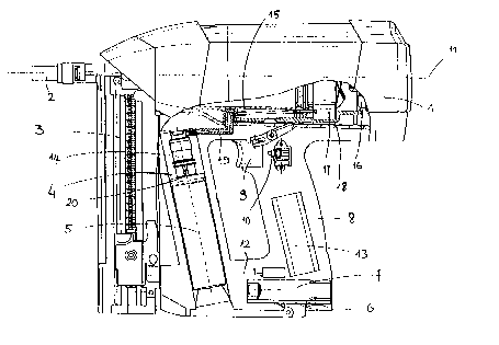
Fixing device using compressed gas, comprising a casing (1) containing a combustion chamber (17), a housing (4) for receiving a cartridge of compressed gas (5), a duct (19) for injecting compressed gas into the combustion chamber (17) from the cartridge (5), a magazine (3) for supplying fixing elements, a housing (6) for receiving a battery (7) for supplying electricity and a handle (8) connected directly to the casing (1) and substantially perpendicular to an axis (11) of the casing (1). The housing (4) for receiving the cartridge (5) extends substantially parallel to the handle (8) and is offset with respect thereto along the axis (11) of the casing (1).

Revendications

Note : Les revendications sont présentées dans la langue officielle dans laquelle elles ont été soumises.


5
WHAT IS CLAIMED IS:
1. Fixing device using compressed gas, comprising a casing (1) containing a
combustion chamber (17). a housing (4) for receiving a cartridge of compressed
gas (5), means (19) for injecting compressed gas into the combustion chamber
(17) from the cartridge (5), a magazine (3) for supplying fixing elements, a
housing (6) for receiving means (7) for supplying electricity and a handle (8)
connected directly to the casing (1) and substantially perpendicular to an
axis
(11) of the casing (1), characterised in that the housing (4) for receiving
the
cartridge (5) extends substantially parallel to the handle (8) and is offset
with
respect thereto along the axis (11) of the casing (1).
2. Device according to claim 1, wherein the housing (4) for receiving the
cartridge (5) is disposed between the handle (8) and the magazine (3) for
supplying fixing elements.
3. Device according to claim 1, wherein a bridge (12) is provided to house
means (7) for supplying electricity, connecting the housing (4), for receiving
the
cartridge (5), and the handle (8).
4. Device according to claim 3, wherein the bridge (12) for housing the means
(7) for supplying electricity connects the respective ends of the housing (4),
for
receiving the cartridge (5), and the handle (8), opposite to their ends which
are
connected to the casing (1).
5. Device according to claim 1, wherein the means (19) for injecting
compressed gas enter substantially in the middle of the combustion chamber
(17).
6. Device according to claim 1, wherein a solenoid valve (14) is provided for
metering compressed gas, extending along an axis (20) as an extension of which
the compressed gas cartridge (5) is intended to extend.

Description

Note : Les descriptions sont présentées dans la langue officielle dans laquelle elles ont été soumises.

io3 au»~~ a 'a~pu~ea ay ~:uo.~ laq~r.~a uor~snqmoo a~ o~m seD passaiduroa
°uraaaCui Toy
sm~~u 'a~i>riuca seD passasdmoa E ~~aaa~ zog ~msno~ a 'zaqamilo uo~snqmoa a
~muT~luoo
~niseo ~ ~u~sudmoa sED passazdzaoa 'utsn aauap Ding E o; saa~ai Bor~nanm aq1
pna sy~ o,~
-~uzo d aauep;d Ieapi
s~ o~ ~aso~o aaznap ~u~~ a~~o W nEr~~o a~i~aa a~ .~uuq o~ ~~nos sn~ s~r~
~.~or~dd~ ate,
-~a~ xapur stq sa~dde zo~szado a~ ~a~M o~
aTp~~ a~ uo ~uiod a ~e ~C~er~aeasqt~s panoursod aq Plno~s ~rn.E~~o ar.~u3o sy
paou~~~q aq o~
anoqe paBgap ad~i a~~o aoinap ~ jog .~apao ul 'uoT~50d Duu~ ate m ~
~nrsrGtq~~s pue aouap
a~ ~~p~eu rri s2t~~no~ip saauauadaa 'ptre~ ano ~ alpae~ ~BUg a~ 4uiddu~ ~d
aouap
a~~ ~ ii~plo i~ ua i~r~ vo~~.ia do u~ ~~ os paouele q ~Iao o d ~nmaaa~ am
saolnap ~u~cg asa~,
'aIP~~I
~aug a~ aprstcr pasno~ st anptn~o Ia~y aq~ saomap .~a~o za s~aiar~nn 'alp~retl
a~ p~ Dmcsea
a~ uaanuaq '~ut5~a a~,~o sixe a~ o~ Ia~ered spma~xa Dmsno~ aDpp~o a~ saornap
ureuao u1
'amze.~~u
~nTd a~ buoy 'aue;Ea arp~o sore a~ o~ ielriarpBadrad ~C~sr~u~~qns spua~a
~~eiauaD
Dmcsnor~ ~a~~q aid, vaiseo aid o~ pazaauuoo Wuaa alpue~ a~ pwe 'apm~ anjd a~
ynn
~uz~~arrnmzuroo aurLeDeaa a~ 'see s~ anole ra~qxo r~aea o~ ~aadsai r~pnn ~as~o
aie pue Dmsea
a~~o sLx~ a~~ o~ ~re~n:~rpnadrad fi~~~~u~~.sqns pua~.ta aipueq ~uu~ a~ pue
a~eDecu pnld a~x
~aomap aouroW u-e~o su~aii~ ~q ~aqu~~ua aousnqtuoo
a~ u~ pam~'~noo sea no~asnq~oa a~q~~o uoiso~dxa ~u~o.uuoa ion .ca~~u~ a
palunouc 5T rio~~,
uo aTp~ W cug E pae f~a~sq E Duv~aaa so3 ~rsno~ g 'sDnTd,~o aBrzeaeru ~
'~cns~ea aq~3o
~uo~ aq.~ ~E .~m~aaCo.~d aprr~ Dntd a 'iaqureqo uonsns~uoo aft oztu se°
passaiduioo Dtrr~oaCm sod
~onp ~ autn~e~ 'sea passaldmoo~o aDpuu~eo a ~uinzaoal ion nuisnorj ~ '~aqrumlo
uopsnqzaoo ~
~amrelBOO ~~ea a ~msudiuoo 'seD passaxdm~oo aro~sn aauap ~n~~ a o~ sa~e~a~
uoauanm a~
s~~ a~ss~~oa ~~sn ~~~~a ~~x~x
SO-ZO-666l ~6909ZZ0 ~a

CA 02260693 1999-02-OS
supplying fi.~dng elements, a hou~g for receiving means for supplying
eJ.ectriciry and a handle
directly connected to the casing and substantially perpendicular to an ate, of
the casing,
characterised in that the cartridge housing e~-tends substamially parallel to
the handle and is
offset with respect tliereto along the ass of the casing.
This type ofrelztzve arrangement ofthe camidge housing and the handle oilers a
better
distribution of the weight of the various elements of the device.
Tlie camidge housing is preferably disposed betwEen the handle and the
magazine for
supplying fi,~ng elements.
In a preferred embodiment, a bridge for housing the means for supplying
electricity is
provided, connecting the cartridge housing and the handle.
The housing for receiving the means for supplying electricity no longer being
connected to the
maga~ne of fia~ing elements, tire device is still supplied electrically wh en
th a magazine is
removed.
The applicant leas also managed to exploit the generally considerable weight
of tine means for
supplying electricity in order to balance the device still further.
The invention wldl be better understood with the aid ofthe following
descriptiozt of a particular
embodiment ofthe fi.~ng deuce of the invez~tzon with reference to the attached
drawing in
which.
- Figure 1 Illustrates a lateral view of tl~e fi.~dng device, and
- Fgure 2 ~lustrates a partial lateral cross-sectional view ofthe device ofthe
figure.
The fi.~ng device ofthe invention is intended to fix fi.~dug elements, in this
case plugs, into a
fining support, a concrete wall, for example, by explosion of compressed gas.
2

CA 02260693 1999-02-OS
Tlie device essentially comprises a casing 1, a plug guide 2 prvjec.'ting out
of the from of the
casing 1, a magazine 3 for supplying plugs, a housing 4 for receiving a
caz'tridge of
compressed gas ~, a housing 6 for receiving a battery 7 for supplying
electricity to the device,
and a handle 8. 'fhe casing I and the plug guide 2 both have an axis 11.
The casing 1 contaitzs a cylinder 15 in which is mounted a plug propellaig
piston, a rear
cylinder vend 16. a combustion chamber 17 and a combustion chamber sleeve 18.
The housing 4 also contains a solez~oi.d valve 1 ~. for metering gas injected
into the combustion
chamber 17, intended to receive an injection join~ag piece for the compressed
gas cartridge ~.
.T..b.e solenoid vatve 1.4 extends along an axis 20 as an e~-iension of
wliicli the con~ressed aas
cartridge 5 is intended to extend after introduction into the housing 4. A
duct 19 for injectlag
compressed gas izzto the coxubusd.on chamber I7 from the camidge 5 connects
the solenoid
valve I4 to the combustion chamber I7 and in this case enters substantially in
the middle of
the combustion chamber 17 along the axis 11.
fhe handle S has a trigger 9 provided to actuate a switch 10 for controlling
an. igniti.ou device
intended to explode the compxeseed gas con~taimed in the combustion chamber
17.
An electronic module 13 for controlling the electronics of the device, and in
particular the
solenoid valve 14 and the i~ition device, is housed inside the handle 8.
The h ap.dle 8, the housing 4 for receivin' the cartridge 5, and the magazine
of plugs 3 extend
in a common plane P containing the axis 1 i, on the same side of the axis 11
in this plane P,
sub stantially p erp endicul ar to th a axis 1 I . Th a la an dle 8 and the
housing 4 fox the cartridge S
are directly connected at one of their ends to the casing 1. The three
elements 8, 4, 5 are thus
substantially parallel to each other. It should be emphasized that the camidge
5, introduced
into its housing 4, extends sub ~antralLy parallel to the handle 3.
The handle 8 is in tliis case co~ected substantially to the middle of the
casing 1, along the axis
11, and the magazuae 3 communicates with the plug guide 2, the ma'azine 3 thus
being offset
3

CA 02260693 1999-02-OS
forwards with respect to the h~dle 8 along the alas l 1. The housing 4 for
receiving the
cartridge 5 i.s also offset forwards with respect to the liandle 8 and is
disposed between the
magazine 3 and the handle 8 along the a.Yis l I.
.4 bridge l? for housing the battery 7, and in which the hoasung 6 for
zeceiving the battery 7 is
arranged, conneWs the respective ends ofthe housing 4, for receiving the
cartridge 5, and the
handle 8 opposite to their ends which are connected to the casing 1. 'floe
bridge 12 and the
battery 7, placed in its housing 6, extend ymbstantially parallel to the axis
11.
Sy reason of the arrangement of the housing 4 for the cartridge 5, of the
bridge 12 for housing
the battery 7, of the handle 8 and of the pluD zvagazine 3 the centre of gz-
avity of the device is
substantially at an ideal point ofbalance which is that an which an operator
places .bis index
finger when holding the device in one hand by means of the handle iz~ order to
f re~ This ideal
point is substantially at the trigger 9.
4

Dessin représentatif
Une figure unique qui représente un dessin illustrant l'invention.
États administratifs

2024-08-01 : Dans le cadre de la transition vers les Brevets de nouvelle génération (BNG), la base de données sur les brevets canadiens (BDBC) contient désormais un Historique d'événement plus détaillé, qui reproduit le Journal des événements de notre nouvelle solution interne.

Veuillez noter que les événements débutant par « Inactive : » se réfèrent à des événements qui ne sont plus utilisés dans notre nouvelle solution interne.

Pour une meilleure compréhension de l'état de la demande ou brevet qui figure sur cette page, la rubrique Mise en garde , et les descriptions de Brevet , Historique d'événement , Taxes périodiques et Historique des paiements devraient être consultées.

Historique d'événement

Description Date
Inactive : Périmé (brevet - nouvelle loi) 2019-02-05
Inactive : Lettre officielle 2015-10-22
Inactive : Correspondance - Transfert 2015-10-02
Inactive : Correspondance - Transfert 2014-04-15
Inactive : CIB de MCD 2006-03-12
Accordé par délivrance 2000-11-21
Inactive : Page couverture publiée 2000-11-20
Inactive : Taxe finale reçue 2000-08-18
Préoctroi 2000-08-18
Requête pour le changement d'adresse ou de mode de correspondance reçue 2000-08-17
Un avis d'acceptation est envoyé 2000-02-24
Lettre envoyée 2000-02-24
Inactive : Approuvée aux fins d'acceptation (AFA) 2000-01-31
Inactive : Page couverture publiée 1999-08-19
Demande publiée (accessible au public) 1999-08-13
Symbole de classement modifié 1999-03-19
Inactive : CIB en 1re position 1999-03-19
Inactive : CIB attribuée 1999-03-19
Symbole de classement modifié 1999-03-19
Exigences de dépôt - jugé conforme 1999-03-05
Inactive : Certificat de dépôt - RE (Anglais) 1999-03-05
Demande reçue - nationale ordinaire 1999-03-04
Exigences pour une requête d'examen - jugée conforme 1998-02-05
Toutes les exigences pour l'examen - jugée conforme 1998-02-05

Historique d'abandonnement

Il n'y a pas d'historique d'abandonnement

Titulaires au dossier

Les titulaires actuels et antérieures au dossier sont affichés en ordre alphabétique.

Titulaires actuels au dossier
SOCIETE DE PROSPECTION ET D'INVENTIONS TECHNIQUES S.P.I.T.
Titulaires antérieures au dossier
BRUNO TOULOUSE
FREDERIC NAYRAC
GUY JAILLET
Les propriétaires antérieurs qui ne figurent pas dans la liste des « Propriétaires au dossier » apparaîtront dans d'autres documents au dossier.
Documents

Pour visionner les fichiers sélectionnés, entrer le code reCAPTCHA :


Pour visualiser une image, cliquer sur un lien dans la colonne description du document. Pour télécharger l'image (les images), cliquer l'une ou plusieurs cases à cocher dans la première colonne et ensuite cliquer sur le bouton "Télécharger sélection en format PDF (archive Zip)" ou le bouton "Télécharger sélection (en un fichier PDF fusionné)".

Liste des documents de brevet publiés et non publiés sur la BDBC .

Si vous avez des difficultés à accéder au contenu, veuillez communiquer avec le Centre de services à la clientèle au 1-866-997-1936, ou envoyer un courriel au Centre de service à la clientèle de l'OPIC.


Description du
Document 
Date
(aaaa-mm-jj) 
Nombre de pages   Taille de l'image (Ko) 
Abrégé 1999-02-04 1 18
Description 1999-02-04 4 156
Dessins 1999-02-04 2 68
Revendications 1999-02-04 1 47
Dessin représentatif 1999-08-18 1 15
Dessin représentatif 2000-10-17 1 18
Courtoisie - Certificat d'enregistrement (document(s) connexe(s)) 1999-03-04 1 117
Certificat de dépôt (anglais) 1999-03-04 1 165
Avis du commissaire - Demande jugée acceptable 2000-02-23 1 166
Rappel de taxe de maintien due 2000-10-09 1 110
Correspondance 2000-08-16 1 32
Correspondance 2000-08-17 1 32
Courtoisie - Lettre du bureau 2015-10-21 1 33