Language selection

Search

Patent 2261118 Summary

Third-party information liability

Some of the information on this Web page has been provided by external sources. The Government of Canada is not responsible for the accuracy, reliability or currency of the information supplied by external sources. Users wishing to rely upon this information should consult directly with the source of the information. Content provided by external sources is not subject to official languages, privacy and accessibility requirements.

Claims and Abstract availability

Any discrepancies in the text and image of the Claims and Abstract are due to differing posting times. Text of the Claims and Abstract are posted:

  • At the time the application is open to public inspection;
  • At the time of issue of the patent (grant).
(12) Patent: (11) CA 2261118
(54) English Title: INFORMATION SYSTEM DISPLAY PANEL
(54) French Title: PANNEAU DE VISUALISATION POUR SYSTEMES D'INFORMATION
Status: Expired
Bibliographic Data
(51) International Patent Classification (IPC):
  • B42F 7/02 (2006.01)
  • B42F 7/00 (2006.01)
(72) Inventors :
  • MAIER-HUNKE, HORST-WERNER (Germany)
(73) Owners :
  • DURABLE HUNKE & JOCHHEIM GMBH & CO. KG (Germany)
(71) Applicants :
  • DURABLE HUNKE & JOCHHEIM GMBH & CO. KG (Germany)
(74) Agent: FETHERSTONHAUGH & CO.
(74) Associate agent:
(45) Issued: 2005-06-14
(86) PCT Filing Date: 1997-07-17
(87) Open to Public Inspection: 1998-01-29
Examination requested: 2001-08-20
Availability of licence: N/A
(25) Language of filing: English

Patent Cooperation Treaty (PCT): Yes
(86) PCT Filing Number: PCT/DE1997/001551
(87) International Publication Number: WO1998/003351
(85) National Entry: 1999-01-15

(30) Application Priority Data:
Application No. Country/Territory Date
296 13 107.5 Germany 1996-07-17

Abstracts

English Abstract


The invention concerns an information system display
panel with a plastics frame surrounding two transparent foils
(4, 5) that form an envelope. The frame (1) is composed
of two halves interconnected by locking couplings such that
peripheral weld seams can be dispensed with.


French Abstract

L'invention concerne un panneau de visualisation pour systèmes d'information comprenant un cadre en plastique qui entoure deux feuilles transparentes (4, 5) formant une pochette. Le cadre (1) se compose de deux moitiés solidarisées par des éléments d'accouplement encliquetables, de manière à éviter d'avoir recours à des soudures périphériques.

Claims

Note: Claims are shown in the official language in which they were submitted.


-4-

CLAIMS:

1. An information system display panel in which
cylindrical pins or holes for hanging in holding devices of
stands, folders or the like are arranged in the region of
the ends of one edge of a plastic frame holding a pocket
formed by transparent films, characterized in that the frame
comprises two frame halves which are joined together by
locking couplings and hold a pocket which is formed by two
transparent films of different sizes, one of which is held
between the frame halves along three and one along all of
its four edges.

2. The display panel according to Claim 1,
characterized in that the locking couplings are formed by a
multiplicity of press studs.

3. The display panel according to Claim 1 or 2,
characterized in that the locking couplings form two rows of
locking couplings which extend over the entire periphery of
the frame and are offset laterally with respect to one
another.

4. The display panel according to Claim 3,
characterized in that the locking couplings of one row of
locking couplings are arranged offset with respect to the
locking couplings of the other row of locking couplings in
the longitudinal direction of the rows of couplings.

5. The display panel according to any one of
Claims 1 to 4, characterized in that the elements of the
locking couplings to be coupled are arranged in a strip-
shaped region of the mutually facing sides of the frame
halves bounded by flat fillets.


-5-

6. The display panel according to any one of
Claims 1 to 5, characterized in that the transparent films
are provided in the region of their edges held between the
frame halves with clearances enclosing at least part of the
locking couplings.

7. The display panel according to any one of
Claims 1 to 6, characterized in that the locking couplings
comprise pins, which have an edge bead, and sockets, which
have a locking groove, are closed towards the frame half
bearing them and free ends of said sockets protrude into
centring grooves surrounding the pins.

8. The display panel according to any one of
Claims 1 to 7, characterized in that the frame halves are
provided in the region of at least one edge of their front
and/or rear side with guide grooves for index-tabs which
index-tabs comprise a lower part consisting of two legs
forming a gap and being provided with portions which fit the
guide grooves.

9. The display panel according to Claim 8,
characterized in that the legs of the index-tabs are
provided with at least one locking projection and the guide
grooves are provided with a multiplicity of locking
recesses.

10. The display panel according to Claim 9,
characterized in that the locking recesses on the front side
of the frame are arranged offset with respect to the locking
recesses on the rear side of the frame.

11. The display panel according to Claim 8 or 9,
characterized in that the distance between the locking
recesses on the front side of the frame is different from


-6-

the distance between the locking recesses on the rear side
of the frame.

Description

Note: Descriptions are shown in the official language in which they were submitted.


CA 02261118 2004-11-08
21568-117
- 1 -
Information system display panel
The invention relates to an information system
display panel in which cylindrical pins or holes for hanging
in holding devices of stands, folders or the like are
arranged in the region of the ends of one edge of a plastic
frame holding a pocket formed by transparent films.
There are known display panels of the
abovementioned type in which the frame and the edges of the
pocket formed by the transparent films are joined together
by welding, one of the transparent films being welded
permanently into the frame along four edges and one of the
transparent films being welded permanently into the frame
along three edges. The known welded joins not only entail
an undesirably high expenditure of energy, they are also not
fully satisfactory with regard to the working result which
can be achieved with them. The invention is based on the
object of providing a display panel of the type under
consideration which, while taking ecological aspects into
account, can be produced cost-effectively and meets high
requirements with regard to its appearance. This object is
achieved according to the invention by the frame comprising
two frame halves which are joined together by locking
couplings and hold at least three respective edges of two
transparent films forming the pocket.
A broad aspect of the invention provides an
information system display panel in which cylindrical pins
or holes for hanging in holding devices of stands, folders
or the like are arranged in the region of the ends of one
edge of a plastic frame holding a pocket formed by
transparent films, characterized in that the.frame comprises


CA 02261118 2004-11-08
21568-117
- 1a -
two frame halves which are joined together by locking
couplings and hold a pocket which is formed by two
transparent films of different sizes, one of which is held
between the frame halves along three and one along all of
its four edges.
The display panel according to the invention
offers the advantage that the parts forming it can be fitted
together quickly and unproblematically and there is no need
for peripheral welds. Unlike in the case of known welded
frames, the outside surfaces of the frame can be of a smooth
design and consequently so-called dirt traps are not formed.
Further details and features of the invention
emerge from the subclaims and the following description

15-JRN-1999 15:31 PR DR BONING +49 30 3043191 S.05i20
WO 98/03351 PCT/DE97/01551
- 2 -
of a particularly advantageous embodiment of the
invention represented in the attached drawing, in
which.
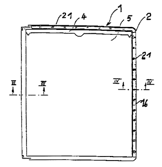
Fzgure 1 shows the pl.awcriew of a display
panel,


, ~, Figure 2 shows the plan view of two transparent


,~


films placed one on top of the other,


Figure 3 shows on an enlarged scale a section


through the frame halves in the region of a joining


l0 point,


Figure 4 shows on an enlarged scale a section


through the frame parts in the region of a locking


recess for an index-tab and


Figure 5 shows an index-tab suitable for


z5 fitting on the frame of the display panel.


In Figure 1, 1 denotes the frame of a display


panel which Comprises two halves 2, 3, between which


two transparent films 4 and 5 are clamped. While the


transparent film 4 facing the half 3 forming the rear


20 side of the frame 1 is held in the frame 1 along all of


its four edges, the transparent film 5 facing the half


2 forming the front side of the frame 1 is anchored on


tp : ~ they frame 1 only along three edges. The transparent


films 4 and S may consist of one piece, which is folded


25 in the region of the lower edge of the frame 1. Two


rows of locking couplings, the structural design of


which is shown by Figure 3, serve for joining the frame


halves 2, 3. Each locking coupling comprises a pin 5,


which is surrounded by an annulax centring groove 7,


30 and a socket 8, which is closed at its lower end and


the free end of which can enter into the centring


groove 7. The pin 6 is provided with an edge bead 9,


which in the locked-in state grips into a locking


groove 10 on the inside wall of the socket 8.


35 The pins 6 and sockets 8 of the inner row of


locking couplings pass clearances 11 formed in the


transparent films 4 and 5 by punched holes. While the


pins 6 arid sockets 8 of the inner row of locking


~ : ,-,~-


CA 02261118 1999-O1-15

15-JRN-1999 15:31 PR DR BONING +49 30 3043191 S.06i20
WO 99/03351 pCT/D1;97/01551
- 3 -


couplings are ful~.y enclosed by the transpaz~ent films
4


and 5 in the region of the edges thereof, the pins 6


and 8 of the outer row of locking couplings are


surrounded only partially by Zikewise punched


semie~.rcular clearances 12. As can be seen from the


clearances 11 and 12 in Figure 2, the locking couplings


of the adjacently arranged rows of locking couplings


are arranged offset with respect to one another in the


longitudinal direction of the xows of couplings. To


ensure flush contact in the region of the peripheral


outer joint of the frame halves 2 arid 3, the elements


of the locking couplings to be coupled lie in a strip-


shaped region 1S of the mutually facing sides of the


frame halves 2, 3 bounded by flat fillets 13, 19, the


height of the outer fillets 14 being greater than the


height of the inner fillets 13 by an amount taking


account of the thickness of the transparent films 4, 5.


At least part of the edges of the frame halves


2, 3 is provided on the front and rear side of the


frame 1 with guide grooves 16, 17 for the legs 1B, 19


of index-tabs 20, locking recesses 21 and 22 into which


locking projections 23 of the index-tabs 20 can engage


serving for the positional $ecurement of the index-tabs


20_ To be able to altex the positions of the index-


tabs 20 in small steps, the locking recesses 2I on the


front. side of the frame 1 are arranged offset with


respect to the locking recesses 22 on the rear side Q~


the frame 1.


CA 02261118 1999-O1-15

Representative Drawing
A single figure which represents the drawing illustrating the invention.
Administrative Status

For a clearer understanding of the status of the application/patent presented on this page, the site Disclaimer , as well as the definitions for Patent , Administrative Status , Maintenance Fee  and Payment History  should be consulted.

Administrative Status

Title Date
Forecasted Issue Date 2005-06-14
(86) PCT Filing Date 1997-07-17
(87) PCT Publication Date 1998-01-29
(85) National Entry 1999-01-15
Examination Requested 2001-08-20
(45) Issued 2005-06-14
Expired 2017-07-17

Abandonment History

There is no abandonment history.

Payment History

Fee Type Anniversary Year Due Date Amount Paid Paid Date
Registration of a document - section 124 $100.00 1999-01-15
Application Fee $300.00 1999-01-15
Maintenance Fee - Application - New Act 2 1999-07-19 $100.00 1999-06-04
Maintenance Fee - Application - New Act 3 2000-07-17 $100.00 2000-06-08
Maintenance Fee - Application - New Act 4 2001-07-17 $100.00 2001-06-20
Request for Examination $400.00 2001-08-20
Maintenance Fee - Application - New Act 5 2002-07-17 $150.00 2002-06-04
Maintenance Fee - Application - New Act 6 2003-07-17 $150.00 2003-06-20
Maintenance Fee - Application - New Act 7 2004-07-19 $200.00 2004-07-09
Final Fee $300.00 2005-03-21
Maintenance Fee - Patent - New Act 8 2005-07-18 $200.00 2005-06-03
Maintenance Fee - Patent - New Act 9 2006-07-17 $200.00 2006-07-04
Maintenance Fee - Patent - New Act 10 2007-07-17 $250.00 2007-06-14
Maintenance Fee - Patent - New Act 11 2008-07-17 $250.00 2008-06-09
Maintenance Fee - Patent - New Act 12 2009-07-17 $250.00 2009-06-08
Maintenance Fee - Patent - New Act 13 2010-07-19 $250.00 2010-06-10
Maintenance Fee - Patent - New Act 14 2011-07-18 $250.00 2011-06-10
Maintenance Fee - Patent - New Act 15 2012-07-17 $450.00 2012-06-26
Maintenance Fee - Patent - New Act 16 2013-07-17 $450.00 2013-06-26
Maintenance Fee - Patent - New Act 17 2014-07-17 $450.00 2014-06-23
Maintenance Fee - Patent - New Act 18 2015-07-17 $450.00 2015-07-07
Maintenance Fee - Patent - New Act 19 2016-07-18 $450.00 2016-07-05
Owners on Record

Note: Records showing the ownership history in alphabetical order.

Current Owners on Record
DURABLE HUNKE & JOCHHEIM GMBH & CO. KG
Past Owners on Record
MAIER-HUNKE, HORST-WERNER
Past Owners that do not appear in the "Owners on Record" listing will appear in other documentation within the application.
Documents

To view selected files, please enter reCAPTCHA code :


To view images, click a link in the Document Description column. To download the documents, select one or more checkboxes in the first column and then click the "Download Selected in PDF format (Zip Archive)" or the "Download Selected as Single PDF" button.

List of published and non-published patent-specific documents on the CPD .

If you have any difficulty accessing content, you can call the Client Service Centre at 1-866-997-1936 or send them an e-mail at CIPO Client Service Centre.


Document
Description 
Date
(yyyy-mm-dd) 
Number of pages   Size of Image (KB) 
Description 1999-01-15 3 129
Abstract 1999-01-15 1 49
Representative Drawing 1999-04-14 1 3
Claims 1999-01-15 3 106
Drawings 1999-01-15 1 24
Cover Page 1999-04-14 1 28
Claims 2004-11-08 3 80
Description 2004-11-08 4 145
Representative Drawing 2005-05-16 1 5
Cover Page 2005-05-16 1 30
Fees 2005-06-03 1 37
Prosecution-Amendment 1999-01-15 1 20
PCT 1999-01-15 8 264
Assignment 1999-01-15 3 122
Prosecution-Amendment 2001-08-20 1 45
Prosecution-Amendment 2001-10-17 1 30
Fees 1999-06-04 1 38
Fees 2002-06-04 1 38
Prosecution-Amendment 2004-04-06 1 28
PCT 1999-01-15 3 121
Prosecution-Amendment 2004-06-15 2 39
Prosecution-Amendment 2004-11-08 7 193
Correspondence 2005-03-21 1 31
Fees 2011-06-10 1 66