Note: Descriptions are shown in the official language in which they were submitted.
CA 02261257 1999-02-08
OPTICAL AMPLIFIER FOR CONSTANTLY ADJUSTING PER-CHANNEL
OUTPUT POWER AND METHOD THEREOF
BACKGROUND OF THE INVENTION
1. Field of the Invention
s The present invention relates to an optical amplifier for constantly
adjusting
per-channel output power and a method thereof, and more particularly, to an
optical amplifier in a wavelength division multiplexed (WDM) system, whose
output
power for each channel is constant, and a method thereof.
2. Description of the Related Art
~o Development of an erbium-doped fiber amplifier (EDFA) as an optical fiber
in the 1990's has contributed to an epoch-making progress in the field of
optical
transmission. A WDM-EDFA has also been developed with a WDM system which
can simultaneously transmit 4 through 16 channels as well as a single channel.
A gain-flattened optical amplifier used in a WDM transmission system has
~s an amplification which varies according to a change in the number of
channels or
the intensity of an input signal. Such a variation in signal amplification
according
to wavelength degrades the flatness of the gain and generates errors in the
system) thus becoming detrimental to long-distance transmission. In the WDM
transmission system adopting the EDFA, it is important to control per-channel
zo output power with respect to the number of channels, since output power
level
transitions of the EDFA occur when the number of channels are changed due to
reconfiguration or defects of a network. That is, since the WDM-EDFA must
equally amplify the optical signals for a plurality of channels, the gain must
be
uniformly maintained for each wavelength. Also, the gain of the WDM-EDFA must
Zs be controlled to have little change according to a change in the number of
channels.
A dynamic gain-controlled erbium-doped fiber amplifier repeater for WDM
networks by C.Konish et al. disclosed in OFC '97 Technical Digest is used to
allow
an amplifier to output a signal of constant intensity. FIG. 1 is a block
diagram of a
1
CA 02261257 1999-02-08
conventional EDFA comprising an amplification unit 10, first and second
couplers
12 and 14, a wavelength monitor unit 16, and a gain control unit 18. The first
and
second couplers 12 and 14 output part of the output signal of the
amplification unit
to the wavelength monitor unit 16. The wavelength monitor unit 16 receives
s and monitors an amplified signal output from the second coupler 14. The gain
control unit 18 controls the gain of the amplification unit 10 in accordance
with the
results of monitoring. The wavelength monitor unit 16 is comprised of an
acoustic-
optic tunable filter (AOTF), a photo diode (PD), and a wavelength counter, and
counts the number of channels of an optical signal amplified by the
amplification
unit. The gain control unit 18 controls the intensity of an output signal by
adjusting
the gain of the amplification unit using a PD or a gain flattener.
However, the conventional structure is very complicated and large and uses
many additional optical devices, so that it is difficult to be used in a real
system.
Also, the output port of the EDFA directly divides an amplified optical
signal, thus
~s having a direct effect on the output of the EDFA.
SUMMARY OF THE INVENTION
To solve the above problems, it is an objective of the present invention to
provide an optical amplifier in which the number of channels and the power of
an
optical signal are checked, and the per-channel output power is constantly
zo controlled by adjusting the gain of an EDFA according to the number of
channels
and the input power, and a method thereof.
Accordingly, to achieve the above objective, there is provided an optical
amplifier whose output power for each channel is constantly controlled, for
amplifying a data channel optical signal when a monitoring channel optical
signal
2s and a data channel optical signal comprised of a plurality of channels are
input
together, the optical amplifier comprising: a channel monitoring unit for
separating
the monitoring channel optical signal, converting the monitoring channel
optical
signal into an electrical signal, extracting the number of channels included
in the
data channel from the converted signal, and outputting the converted signal;
an
3o amplification unit for amplifying the data channel optical signal using a
predetermined driving source; an amplification control unit for controlling
the input
z
CA 02261257 1999-02-08
of the driving source so that a target output power value of the amplification
unit
depending on the number of channels is actually equal to a measured output
power value of the amplification unit; and a wavelength coupling unit for
converting
the output signal of the channel monitoring unit into an optical signal and
coupling
s the optical signal to the amplified data channel optical signal.
To achieve the above objective, there is provided a method of constantly
controlling the output power for each channel of an optical amplifier,
comprising
the steps of: (a) measuring the output power of the optical amplifier while
changing the number of channels of a data channel optical signal, and storing
the
~o number of channels and the output power values depending on the number of
channels, when the power for each channel of the optical amplifier for
amplifying
the data channel optical signal comprised of a plurality of channels is
constantly
controlled; (b) interpreting a change in the number of channels of the data
channel
optical signal included in the input optical signal by measuring the power of
the
~s input data channel optical signal, and extracting the number of channels
from the
data channel optical signal; (c) setting an output power value of the optical
amplifier corresponding to the extracted number of channels, among the output
power values stored in the step (a)) as a target value; (d) measuring the
output
power for the input signal light amplified by the optical amplifier; and (e)
adjusting
2o the gain of the optical amplifier so that the measured value becomes
actually
equal to the target value.
BRIEF DESCRIPTION OF THE DRAWINGS
The above objectives and advantages of the present invention will become
more apparent by describing in detail a preferred embodiment thereof with
is reference to the attached drawings in which:
FIG. 1 is a block diagram illustrating the configuration of a conventional
optical amplifier;
FIG. 2 is a block diagram illustrating the configuration of an optical
amplifier
for constantly controlling per-channel output power, according to the present
so invention;
3
CA 02261257 1999-02-08
FIG. 3 is a flowchart illustrating a method of constantly controlling per-
channel output power of an optical amplifier, according to the present
invention;
FIGS. 4A and 4B are graphs showing output for each channel when a two-
channel optical signal is input to an optical amplifier according to the
present
s invention; and
FIGS. 5A and 5B are graphs showing output for each channel when a four-
channel optical signal is input to an optical amplifier according to the
present
invention.
DESCRIPTION OF THE PREFERRED EMBODIMENT
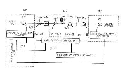
Referring to FIG. 2, an optical amplifier includes a channel monitor unit 200,
a first optical coupler 210, a first photo diode (PD) 211, a first isolator
220, an
amplification unit 230, an amplification control unit 240, a second isolator
250, a
second optical coupler 260, a second PD 261, an external control unit 270, and
a
wavelength coupling unit 280.
~s The channel monitor unit 200 decouples a monitoring channel optical signal
from which information on the number of channels is extracted, when a data
channel optical signal and the monitoring channel optical signal for
monitoring data
channels are coupled to each other and received as input. The channel monitor
unit 200 includes a first wavelength selective coupler (WSC) 201, an optical-
to-
2o electrical converter 202, and a system control unit 203. The first WSC 201
decouples the monitoring channel optical signal from the input optical
signals. The
optical-to-electrical conversion unit converts the decoupled monitoring
channel
optical signal into an electrical signal. The system control unit 203 extracts
information on the number of channels input to the optical amplifier from the
2s monitoring channel electrical signal. Also, the system control unit 203
adds
information on the amplification state of the amplification unit 230 output by
the
amplification control unit 240 to the monitoring channel electrical signal.
The amplification unit 230 amplifies the data channel optical signal using a
driving source. The amplification unit 230 includes a second WSC 231, an
so erbium-doped optical fiber (EDF) 233, a third WSC 234, and first and second
pumping optical sources 232 and 235 as amplification driving sources for the
EDF
4
CA 02261257 1999-02-08
233. The second WSC 231 couples a pumping light of the first pumping optical
source 232 to the data channel optical signal, and the third WSC 234 outputs
the
pumping light of the second pumping optical source 235 to the EDF 233.
The wavelength coupling unit 280 converts the monitoring channel electrical
s signal output from the system control unit 203 into an optical signal,
couples the
converted optical signal to the data channel optical signal amplified by the
amplification unit 230, and transmits the resultant signal to the next port.
The
wavelength coupling unit 280 includes a fourth WSC 281 and an electrical-to-
optical converter 282. The electrical-to-optical converter 282 converts a
system-
monitoring channel electrical signal output from the system control unit 203
into an
optical signal. The fourth WSC 281 couples the amplified data channel optical
signal to the monitoring channel optical signal.
The operation of the optical amplifier having such a configuration will now
be described. The channel monitoring unit 200 separates a monitoring channel
~s wavelength using the first WSC 201, and converts the monitoring channel
optical
signal into an electrical signal using the optical-to-electrical converter
202. The
system control unit 203 extracts the information on the number of input
channels
of the current amplification unit from the monitoring channel electrical
signal.
The first optical coupler 210 separates about 1 % of the data channel optical
2o signal passed through the first WSC 201. The first PD 211 converts the data
channel optical signal into an electrical signal, and outputs the electrical
signal to
the amplification control unit 240. The second optical coupler 260 separates
about
1 % of the data channel optical signal which is amplified by the amplification
unit
230 and passed through the second isolator 250. The second PD 261 converts
25 the separated data channel optical signal into an electrical signal, and
outputs the
electrical signal to the amplification control unit 240.
The amplification control unit 240 checks the power of a data channel
optical signal input to the amplification unit 230 from the magnitude of an
electrical
signal received from the first PD 211, and determines whether data channels
are
3o added or dropped. The gain of the amplification unit 230 is controlled by
the
results of the check on the amplification power. The amplification control
unit 240
CA 02261257 1999-02-08
informs the system control unit 203 of the amplification state of the
amplification
unit 230.
The external control unit 270 is connected to the amplification control unit
240 via an RS-232C cable, and allows a user to Check the state of the
amplification unit 230 from the outside and control the amplification
characteristics
of the amplification unit 230 by adjusting the parameters of the amplification
unit
230.
In the amplification unit 230, the gain is controlled by the pumping power of
the first and second pumping optical sources 232 and 235 which are controlled
by
~o the amplification control unit 240. The amplification unit 230 amplifies a
data
channel optical signal by the controlled amplification degree.
Amplification is accomplished as follows. When a pumping light having a
center wavelength of 980nm from the first and second pumping sources 232 and
235 is applied to the EDF 233, the implanted pumping light excites erbium ions
of
a base state in the EDF 233, the EDF being an amplification medium doped with
a
rare-earth element such as erbium (Er). The data channel optical signal is
amplified by stimulated emission of the excited erbium.
The first and second isolators 220 and 250 improve the gain and noise
figures of an amplified signal by blocking forward and reverse amplified
Zo spontaneous emission generated by the EDF 233 and beams reflected by an
optical device connected to each of the isolators 220 and 250.
The wavelength coupling unit 280 converts the monitoring channel electrical
signal, in which amplification state data of the amplification unit 230 is
contained,
to an optical signal using the electrical-to-optical converter 282, recouples
the
zs amplified data channel optical signal and the monitoring channel optical
signals
using the fourth WSC 281, and transmits the resultant signal to the next
amplification port or receiving port.
FIG. 3 is a flowchart illustrating a method of constantly controlling the per-
channel output power of an optical amplifier, according to the present
invention.
so The operation of the present invention will now be described referring to
FIG. 3.
First, the output for each channel of the amplification unit 230 is constantly
controlled, the output values of the second PD 261 which depend on the number
6
CA 02261257 1999-02-08
of input channels are measured by varying the number of channels between the
maximum and minimum number of channels capable of being amplified by the
EDF 233. The output values of the second PD 261 according to the number of
channels are stored as data in a storage unit (not shown) installed in the
s amplification control unit 240) in step 300. Alternatively, the power output
for each
channel is determined to be a plurality of values, and the output value of the
second PD 261 to be measured with respect to each of the determined output
values is stored as data in the storage unit installed in the amplification
control unit
240. A user can select a desired output value for each channel from values
~o stored in the amplification control unit 240 using the external control
unit 270. The
external control unit 270 is connected to the amplification control unit 240
via the
RS-232 cable.
The first WSC 201 decouples the monitoring channel optical signal from the
input optical signals. The optical-to-electrical converter 202 converts the
decoupled monitoring channel optical signal into an electrical signal and
stores the
electrical signal in the system control unit 203. The system control unit 203
extracts the number of channels of a data channel optical signal from a
monitoring
channel.
The amplification control unit 240 checks the power of an input optical
2o signal received from the first PD 211, interprets a change in the number of
channels, and reads the number of channels extracted from the system control
unit 203.
The amplification control unit 240 reads a target output value of the second
PD 261 depending on the number of channels extracted from data stored in the
2s system control unit 203, in step 302. The amplification control unit 240
measures
the output power of a data channel optical signal amplified by the
amplification unit
230 by measuring the output value of the second PD 261, in step 304. The
amplification control unit 240 compares the target value of the step 302 to
the
measured value of the step 304, in step 306. If the two values are actually
the
so same, the information on the current amplification unit 230, e.g., the
number of
channels, the driven current value of a pumping optical source, etc., is
output to
the system control unit 203 or the external control unit 270. The system
control
7
CA 02261257 1999-02-08
unit 203 adds amplification state data of the current amplification unit 230
output
from the amplification control unit 240 to the monitoring channel data and
outputs
the result to the electrical-to-optical converter 282. The electrical-to-
optical
converter 282 converts a monitoring channel electrical signal input from the
s system control unit 203 into an optical signal. The fourth WSC 281 couples
the
monitoring channel optical signal to the data channel optical signal amplified
by
the amplification unit 230, and transmits the coupled signal to the next
amplification port or receiving port, in step 310.
If the target value of the step 302 is actually not equal to the measured
value of the step 304, the amplification control unit 240 actually equalizes
the two
values by controlling the input current of the first and second pumping
optical
sources 232 and 235 according to the difference between the target value and
the
measured value) in step 308. If the output value for each channel is
misselected
by the user or the number of channels are changed, the output value of a new
~s standard of the second PD 261 becomes a target value, and the output for
each
channel is thus maintained. That is, as described above, when the per-channel
output is selected, the gain is controlled by the amplification control unit
240 even
when the intensity of an input signal for each channel or the number of
channels
are changed, so that the per-channel output is constantly maintained. In
2o particular, when the number of channels was changed according to whether
channels are coupled or divided, transient overshoot of each channel power is
suppressed, so that the output is constantly maintained.
FIGS. 4A and 4B are graphs showing output for each channel when optical
signals of two channels having wavelengths of 1542nm and 1560nm respectively,
zs are input to an optical amplifier according to the present invention. FIG.
4A refers
to the case in which the input power for each channel is -15dBm, and FIG. 4B
refers to the case in which the input power for each channel is -20dBm, each
showing a constant output of +SdBm independently of the intensity of input.
Here,
a doted line indicates an input waveform, and a solid line indicates an output
so waveform.
FIGS. 5A and 5B are graphs showing output for each channel when optical
signals of four channels having wavelengths of 1542nm, 1548nm, 1554nm and
8
CA 02261257 1999-02-08
1560nm respectively, are input to an optical amplifier according to the
present
invention. FIG. 5A refers to the case in which the input power for each
channel is
-15dBm, and FIG. 5B refers to the case in which the input power for each
channel
is -20dBm, each showing a constant output of +SdBm independent of the
intensity
s of input. Here, a doted line indicates the input waveform, and a solid line
indicates the output waveform.
According to the present invention, when an input optical signal having a
plurality of data channels is amplified, the output power for each channel can
be
maintained constantly by controlling the amplification degree of an
amplification
unit to make the target value of the output value for each channel actually
the
same as a real measured value. In particular, the output for each channel can
be
kept constant even when the intensity of an input signal or the number of
channels
are changed, so that an optical amplifier according to the present invention
can be
used in a channel coupling/division system.
Also, many additional optical devices are not necessary, and the optical
amplifier has a simple structure, so the optical amplifier is easy to be
applied to a
real optical communications system.
Furthermore) the output power for each channel is represented as data with
respect to optical signals of a plurality of channels, the output power for
each
2o channel can be selected from data values by a user. Thus, the output power
for
each channel required differently according to the structure of a transmission
system can be selected.
9