Note: Descriptions are shown in the official language in which they were submitted.
CA 02261341 2007-02-16
SIX-PLEATED CATHETER BALLOON
AND DEVICE FOR FORMING SAME
Background Of The Invention
The present invention relates generally to the use
and preparation of balloon catheters for angioplasty and
other surgical procedures and more specifically, to a
multiple pleated balloon and a device for forming
multiple pleats in such balloons.
The use of angioplasty to relieve blockages, or
occlusions, of blood vessels has increased significantly
in recent years. Angioplasty typically involves the
insertion of an inflatable balloon into an occluded blood
vessel and positioning the balloon at the occlusion. The
balloon is then rapidly inflated and deflated in order to
expand the occlusion and restore the blood vessel to its
original, workable size.
Angioplasty catheters which are used for these
procedures typically include a guidewire, a balloon
catheter having a guide lumen which receives the
guidewire, an inflation lumen extending to the distal end
of the catheter and an inflatable balloon positioned at
the distal end of a catheter over an opening of the
inflation lumen. The balloons used with such catheters
typically have an inflatable body portion disposed
between two leg portions. The leg portions have a
diameter which may be slightly less than the diameter of
the catheter at its distal end in order to provide a
tight seal which permits inflation and deflation of the
balloon. The balloon body portion may have a diameter
greater than that of the leg portions and the catheter
shaft. Typically, this diameter corresponds to the actual
diameter of the balloon when inflated, particularly when
a non-expandable material is used for construction of the
balloon.
The inflated diameter of angioplasty balloons may
range anywhere from between 1.5 to 5.0 mm, while the
diameter
CA 02261341 2007-02-16
2
the catheter at its distal end is in the order of 1.0 mm.
The excess balloon material is rolled when deflated upon
the catheter distal end portion to facilitate insertion
of the balloon into the blood vessel. When so prepared,
the balloon will not impinge upon the walls of the blood
vessel as it is being positioned within the blood vessel
at the site of the occlusion. This balloon preparation is
usually accomplished by manually rolling the body of the
balloon onto the catheter shaft. Because of the very
small dimensions of these balloons, it is difficult and
time consuming to ensure that the balloon is accurately
and preferably uniformly folded upon itself.
When such balloons are rolled upon their supporting
catheters with only one or two folds, the deployment of
the balloon during inflation may not occur in a uniform
manner, leading to problems in opening the occlusion in
the vessel. Additionally, in clearing the occlusion the
balloon typically undergoes rapid inflation and
deflation. In balloons having one or two folds, when the
balloon is deflated, the folds may be too large to permit
the balloon to pass rearwardly through the occlusions.
U.S. Patent No. 5,783,227, assigned to the assignee
of the present invention, describes the use of a multiple
part balloon press for forming folds in an angioplasty
balloon in which the balloon press has two balloon-
contacting members with a central channel extending along
at least one of the balloon contacting members. Although
this device is effective for forming two opposing folds
in the catheter balloon, the press must be used
repeatedly at different angular orientations in order to
form more than two folds in the catheter balloon. It may
be difficult to utilize this device to form more than two
uniform folds in the catheter balloon. Using the device
in this manner may lead to undesirable inaccurate forming
of folds which may affect the inflation properties of the
balloon.
U.S. Pat. No. 5,342,307, issued Aug. 30, 1994 and
U.S. Pat No. 5,350,361, issued Sep. 27, 1994 describe
dilation
CA 02261341 2004-03-12
3
balloons with three folds. Although the balloons therein have three folds,
the diameter of the balloon in an uninflated state is still relatively large
due
to the three folds, and a physician may have some difficulty in pulling the
distal end of the catheter rearwardly through a lesion in the blood vessel.
Additionally, in balloons having three such folds, the folds define three
"wings" of the balloon which must be wrapped around the catheter shaft to
facilitate removal of the catheter and balloon from the blood vessel. The
length of these wings are such that they require the catheter distal end to
be rotated for almost one revolution to complete the wrapping of the
balloon wings or folds upon the catheter. This increases the complexity of
the dilation procedure. To applicants' belief, there are no dilation balloons
in the art that utilize more than three folds.
The present invention therefore is directed to a six-pleated
catheter angioplasty balloon and a device for forming multiple pleats in
such balloons while they are attached to the catheter shaft and which
simplifies rolling or folding of the balloon body onto the catheter shaft. The
present invention therefore ensure that the proper folded configuration of
the balloon on the catheter distal end portion is achieved prior to insertion
of the balloon catheter into the blood vessel.
Summary of the Invention
Accordingly, the present invention is directed towards the
provision of a pleating device for forming folds in angioplasty balloons
which is compact and which reliably forms at least six folds, or pleats in a
dilation balloon, typically an angioplasty balloon in a uniform manner that
facilitates wrapping of the balloon around the catheter shaft.
The present invention is further directed towards the provision
of a multi-pleated balloon for an angioplasty catheter in which the balloon
has multiple pleats, preferably six pleats, uniformly spaced around the
circumference of the balloon. The pleats are formed in the balloon in a
device while the balloon is inflated. This device includes a plurality of
CA 02261341 2004-03-12
4
balloon-contacting members that simultaneously impinge upon the inflated
balloon at six different, equally spaced locations around the balloon
perimeter so that the resulting balloon folds or pleats are uniform.
The present invention is also directed towards the provision
of a balloon forming device suitable for use with percutaneous transiuminal
coronary angioplasty (PTCA) catheters and other dilation catheters, the
device comprising a balloon-supporting jig having multiple balloon-
contacting members disposed thereon in equal locations around the
circumferential perimeter of the balloon, the balloon-contacting members
being biased into an open position to permit entrance of an inflated balloon
therein and operable into a closed position wherein the balloon-contacting
members extend radially inwardly into contact with the balloon, to thereby
form a plurality of folds in the balloon body at predetermined intervals
around the circumference of the balloon.
The present invention additionally is directed towards the
provision of a method for forming six pleats in angioplasty balloon secured
to and around the distal end portion of an angioplasty catheter, wherein the
method comprises the steps of inflating the balloon to a distended state,
providing a balloon forming assembly with a plurality of balloon-contacting
members disposed thereon at equal intervals around the exterior
circumference of the balloon, inflating the balloon and placing the inflated
balloon into the assembly between opposing balloon-engagement surfaces
of the balloon-contacting members, drawing the confronting balloon-
engagement surfaces into contact with the balloon and deflating the balloon
during such contact to thereby form at multiple folds in the balloon body
portion.
The present invention further is directed towards the provision
of a dilation balloon for a dilation catheter having six or more pleats formed
in a body portion of the balloon, the pleats defining wings in the balloon
that
may be wrapped around the shaft of the dilation catheter, the wings of the
CA 02261341 2004-03-12
balloon having a length that extends around the catheter shaft that is less
than one-half of the catheter shaft circumference.
Accordingly, with one aspect of the present invention, there is
5 provided an improved dilation balloon catheter for use in dilation therapy,
wherein the balloon catheter is inserted into a blood vessel of a patient and
alternately placed into an inflated condition and a deflated condition within
the blood vessel by an operator from a remote location, comprising:
An elongated catheter terminating in a distal end portion, the
catheter having a shaft of predetermined diameter and a given
circumference, said catheter including an inflation lumen extending through
said catheter and terminating in an inflation port near said distal end,
The catheter further including an inflatable dilation balloon
disposed on said catheter shaft near said distal end portion thereof, the
balloon having a generally cylindrical balloon body portion with two
opposing annular transition portions between said cylindrical body portion
and two opposing ends with two opposing annular transition portions
between said cylindrical body portion and said cylindrical body having a
first preselected diameter when said balloon is in said inflated condition,
two catheter securement portions adjoining said balloon body portion at
said opposing ends thereof, the catheter securement portions having a
diameter smaller than that of said balloon body portion at said first
preselected diameter, said catheter securement portins being affixed to
said catheter shaft on opposite sides or said inflation port,
The balloon body portion including six pleats formed at
circumferential intervals around said balloon body portion when said
balloon is in said deflated condition, said balloon having a second
preselected diameter in said deflated condition that is less than said first
preselected diameter.
The balloon pleats defining corresponding wings of said
balloon.
CA 02261341 2004-03-12
5A
The wings extending the full length of the balloon body
between said transition portions, each of said wings having an end tip
spaced apart from said catheter shaft, said wings further each having a
width defined between said wing end tip and said catheter shaft said
balloon having a blood vessel insertion condition at which said balloon
wings are wrapped around said catheter shaft, said balloon wing width
being such that each wing overlaps an adjoining balloon wing when said
wings are wrapped around said catheter shaft or said blood vessel insertion
condition.
In another aspect of the invention, there is provided An
angioplasty balloon for an angioplasty catheter assembly wherein the
catheter assembly includes an enlongated catheter with a distal end
portion and a given circumference, the catheter including a hollow inflation
lumen extending through said catheter and terminating near said distal
end portion in an inflation opening, the balloon being capable of being
inflated and deflated under pressure from an inflation media supplied
through said catheter lumen, said balloon comprising:
Two leg portions disposed at opposite ends of said balloon
which engage said catheter distal end portion, an inflatable body portion
intermediate of said balloon leg portions, said balloon body portion having a
diameter greater than a diameter of said catheter distal end portion.
The balloon further including six pleats formed in at least said
balloon body portion, the balloon pleats having a length extending
longitudinally along the entirey of said balloon body portion and being
spaced at intervals from each other around the circumference of said
catheter distal end portion
The balloon pleats having a width that extends radially out
from said catheter shaft when said balloon is in a deflated condition
CA 02261341 2004-03-12
5B
Each balloon circumferentially around said catheter shaft
distal end portion when said balloon is in said deflated condition and
Each said balloon pleat width extends only between about
700 and about 90 around said catheter shaft circumference.
Features and advantages of the present invention will be
clearly understood through a consideration of the following detailed
description.
Brief Description of The Drawings
In the course of the following detailed description, reference
will be frequently made to the accompanying drawings in which:
FIG. 1 is a perspective view of a conventional balloon
catheter illustrating the distal end portion thereof;
FIG. 1A is a diagrammatic view illustrating the extent of the
balloon of the catheter of FIG. 1 in an inflated and uninflated state;
FIG. 2 is a cross-sectional view of a blood vessel with two
occlusions and with a balloon catheter inserted therein;
FIG. 3 is a perspective view of the distal end of a balloon
catheter constructed in accordance with the principles of the present
invention, with the balloon illustrated in an inflated state;
FIG. 4 is a plan view of the catheter balloon of FIG. 3;
FIG .4A is a cross-sectional view of the catheter balloon of
FIG. 4 taken along lines A-A thereof;
FIG. 5 is a perspective view of the balloon catheter of FIG. 4
with the balloon illustrated in a partially deflated state to illustrate the
pleats
of the balloon;
FIG. 6 is a plan view of the catheter balloon of FIG. 5;
CA 02261341 2004-03-12
5C
FIG. 6A is a cross-sectional view of the catheter balloon of
FIG. 6 taken along lines A-A thereof and illustrating the pleats of the
balloon;
CA 02261341 1999-02-09
-6-
FIG. 6B is the same view of as FIG. 6A with the
catheter removed for clarity and with the balloon pleats
wrapped around the catheter;
FIG. 7 is a perspective view of the balloon catheter
of FIG. 5, partially in section illustrating the manner in
which the deflated balloon may be folded around the catheter
and its relationship to the catheter shaft;
FIG. 8 is a cross-sectional view of a three pleated
or tri-fold balloon catheter with the balloon deflated;
FIG. 8A is the same view as FIG. 8 with the balloon
pleats folded around the catheter shaft;
FIG. 9 is an elevational view of a device suitable
for forming the pleats in the balloons of the balloon
catheters of FIG. 3;
FIG. 10 is a top view of the balloon forming device
of FIG. 9;
FIG. 11 is an end view of the balloon forming device
of FIG. 9;
FIG. 12 is a cross-sectional view of the balloon
forming device of FIG. 9 taken along lines 12-12 thereof and
illustrating the gear assembly that drives the balloon-
contacting members;
FIG. 13 is an end view of the left end of the
balloon-forming device of FIG. 9 illustrating the balloon
support and the balloon-contacting members in an open
arrangement;
FIG. 14 is the same view as FIG. 13 but illustrating
the balloon-contacting members in a closed position; and,
FIG. 15 is an enlarged detail view of the balloon
and the balloon-contacting members of FIG. 13.
Detailed DescriRtion Of The Preferred Embodiments
A conventional dilation balloon catheter assembly is
illustrated generally at 10 in FIG. 1. Such balloon catheter
assemblies 10 are commonly used in angioplasty, or other
dilation procedures for clearing partially or substantially
blocked blood vessels. As is known in the art, the catheter
CA 02261341 2007-02-16
7
assembly 10 is typically inserted into a blood vessel and
moved through the vessel to the site of the blockage where
it is inflated and deflated to compress and reduce the
blockage.
The catheter assembly 10 is conventional in
construction and is seen to include an elongated catheter 14
with a guidewire lumen 16 extending longitudinally
therethrough. A guidewire 18, which is received within the
lumen 16, permits positioning of the distal end 20 of the
catheter assembly 10 within an occlusion 26 of a blood
vessel 28 as illustrated in FIG. 2.
An inflation lumen 19 also extends through the catheter
14 and terminates in an inflation opening or port 21 shown
in phantom in FIG. 1. An inflatable dilation balloon 22 is
attached to the catheter shaft 24 at the distal end 20 and
overlies the inflation port 21 thereof. As illustrated in
FIG. 1A, the balloon 22 when inflated, has an inflated
diameter DI. This inflation is done under pressure of an
inflation media pumped through the inflation lumen 19 and
into the balloon 22 through the inflation port 21. When
inflated, the balloon will press outwardly against the
occlusion 26 and achieve its inflated diameter taking a
configuration such as that represented by the dashed circle
of FIG. lA.
The balloon 22 is then deflated by withdrawing the
inflation media out of the inflation port 21 and the balloon
22 will collapse in the general manner as illustrated in
FIG. 1A. At this stage, the balloon 22 may be considered as
having a deflated diameter DU which most times will be
slightly less than DI. This deflation in effect causes the
formation of wings, or folds, 30 that extend out from the
catheter. These wings 30, due to their extent E2, (the
distance from an end of the wing 30 to the catheter shaft
24,) may catch or hang up on a second occlusion 27 in the
blood vessel. One solution to this is to rotate the catheter
either clockwise or counterclockwise in the hope that the
wings 30 will wrap themselves around the catheter shaft and
adopt a low profile.
The present invention is directed to a balloon
structure that overcomes the aforementioned shortcomings.
CA 02261341 2007-02-16
8
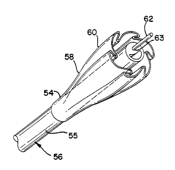
FIG. 3 illustrates a dilation balloon 50 constructed in
accordance with the principles of the present invention.
The balloon 50 is depicted as part of an overall catheter
assembly 52. The balloon 50 is shown inflated in FIGS. 3, 4
& 4A and has an inflated diameter of D1. The balloon 50 has
two opposing end or leg portions 54 that secure the balloon
50 to the catheter shaft 55. These leg portions 54 may have
a diameter that is less than that of the catheter 56 to
firmly engage the catheter 56 and to provide a seal
thereagainst during inflation and deflation of the balloon
50. These leg portions 54 may also be sealed to the
catheter in other conventional manners.
The balloon 50 also may have as illustrated, two
annular transition portions 58 that are disposed adjacent
the balloon leg portions 54 and ramp, or extend, up to a
body portion 60 of the balloon which has a working length L
that extends between the transition portions 58. The
balloon 50 is positioned by a physician within a blood
vessel 28 in the manner illustrated in FIG. 2 by the use of
a guide wire 62 that extends through a guidewire lumen 63
in the catheter shaft 55.
As is known in the art, the balloon 50 may be formed
form a variety of materials, such as nylon, PET
(polyethylene terephthalate) which has relatively no
expansion characteristics to a polyamide homopolymer,
copolymer or blend of polyamide homopolymer and copolymer,
which has highly controlled expansion characteristics. No
matter what type of material is used for the balloon 50,
when the balloon 50 has no such pleats, the body portion 60
of the balloon 50 extends outwardly from the catheter shaft
55 of the catheter assembly 52 when the balloon 50 is in
either an inflated or uninflated state. The diameters D1 of
the balloon body portions 60 may vary from about 1.5 to
about 5.0 mm while the diameter of the catheter is in the
order of about 1 mm. Thus, the extension of the balloon 50
in an unpleated condition will therefore be somewhat large
compared to the diameter of the catheter shaft 55, anywhere
from about 150% to about 500% thereof.
CA 02261341 1999-02-09
-9-
Thus, the balloon body portion 60, inasmuch as it
extends from the catheter shaft 55, may prove to be a
temporary impediment to the insertion of the balloon catheter
52 into the blood vessel 28 because it may flap around and
catch on portions or walls of the blood vessel 28 or on the
occlusions 26, 27. In order to prevent this problem, the body
portion 60 of the balloon 50 is typically wrapped around the
catheter shaft 55 prior to insertion or retraction of th.e
catheter assembly 52 into the blood vessel 28.
In an important aspect of the present invention and
as illustrated in FIGS. 4-6, the balloons 50 of the invention
are formed with multiple folds or pleats 70, with six such
pleats 70 being illustrated. These pleats 70 occur primarily
in the body portion 60 of the balloon 50 and have a length, or
extension, E6 that, when formed, cooperatively define an
overall uninflated diameter D6 of the balloon 50.=
These multiple pleats 70 may be considered as
"wings" that when the balloon 50 is uninflated as illustrated
in FIG. 6A, extend radially outwardly from the catheter and
which serve to reduce the overall uninflated diameter D6 of
the balloon 50. The folds 70 are preferably formed at equal
intervals (further preferably at about 600) around the
circumference of exterior surface 64 of the balloon body
portion 60. The use of six such folds 70 is significant
because it significantly reduces the extent that the balloon
folds 70 project when the balloon is initially deflated to the
form of the FIG. 6A, which may be considered as a primary
profile of the balloon when ready for insertion.
These pleats 70 have an extent E6 that equals the
distance from the catheter shaft 55 to the pleat end 65. The
six pleats 70 reduce the immediate deflated profile of the
balloon 50 as illustrated in FIG. 5 so that the projecting
wing extent E6 is significantly small, approaching the order
of about approximately 125% of the diameter Dc of the catheter
_.shaft 55. In between the pleats or folds 70, troughs 72 exist
to separate the folds 70 form one another. When so pleated,
the pleats 70 may be wrapped upon the catheter shaft 55 in the
CA 02261341 2008-02-11
manner illustrated in FIGS. 6B & 7, wherein each pleat 70
will overlie an adjoining pleat to some small extent. The
manner in which the balloon folds 70 appear after such
wrapping is generally shown in FIG. 6B. FIG. 7 may be
considered as having a secondary profile of the balloon when
it has been deflated after inflation and when it is ready
for retraction into the guiding catheter.
FIG. 8 illustrates, in cross-section, a balloon
catheter assembly 200 in which the dilation balloon 202
thereof has three folds or pleats 204 when the balloon 202
is in the uninflated condition illustrated. The balloon 202
is of conventional size, that is, the inflated diameter
thereof is about 0.16 inches (4.0 millimeters). The three
pleats 204 cooperatively define an uninflated diameter D3 of
the balloon 202. Each balloon pleat 204 has an extent E3 that
runs from the catheter shaft 201 to a respective end tip
206. Such balloons 202 are known in the art as described
above. This balloon fold arrangement leads to certain
shortcomings. For example, the uninflated and unwrapped
diameter D3 of such a tri-fold balloon 202 having a balloon
thickness of about 0.001 inches (0.02 millimeters) will be
approximately 0.155 inches (3.93 millimeters). The extent E3
of each pleat 204 is sufficiently long that it extends
rather long circumferentially around the catheter 201. This
extent is represented in FIG. 8A as angle 03that extends
around the circumference of the catheter 201 for a range of
between approximately 220 and approximately 270 .
In the balloons 50 of the present invention, the
increased number of pleats 70 significantly reduces the
uninflated and unwrapped diameter D. of the balloon 50. For
example, in a six pleated balloon having an inflated
diameter of about 0.16 inches (4.0 millimeters) and a
balloon wall thickness of about 0.001 inches (0.02
millimeters), will have a deflated diameter of approximatel,,r
0.090 ;nches (2.28 millimeters). The inflated diameter of
the balloon may vary from 0.078 inches to 0.31 inches. The
increased number of pleats 70 reduces the uninflated
diameter D6 of the balloons of the present invention by
almost 43% as compared to the uninflated and
CA 02261341 2007-02-16
11
unwrapped diameter (0.155 inches and 3.93 millimeters) of
the conventional tri-fold balloon exemplified in FIG. 8.
The extent E6 of each pleat 70 is significantly reduced and
extends circumferentially when wrapped around the catheter
shaft 55 through a range of angles between approximately
700 and 90 and preferably less than 90 .
This reduced distance is significant to the operation
of the balloon catheter assembly because it reduces the
effort to wrap a deflated balloon 50 onto the catheter
shaft 55 by the operating physician. Such a catheter need
only be rotated about one-quarter turn to wrap the balloon,
while a tri-fold balloon catheter would have to be rotated
about three-quarters of a turn. The wrapping with the
balloons of the present invention should require no more
than a simple wrist rotation. Balloons having diameters of
about between 3.5 and about 5.0 millimeters will benefit
from such pleating.
FIG. 9 illustrates a device 100 for forming six or
more pleats 70 in the balloons 50 of the present invention.
The device 100 is small and hand-operated. It includes a
mounting base 102 that supports three vertical columns 104,
105 and 106 that support the balloon forming components of
the device 100. A manually manipulatable knob 108 is
provided at one end thereof and is rotatably supported in
an opening (not shown) in the first column 104. This knob
is operatively connected to a plurality of balloon-
contacting members 110 (FIG. 12) that are rotatably
disposed on the first column 104. A slip clutch mechanism
112 is interposed between the knob 108 and the first column
104 and the clutch 112, in turn, governs the speed at which
a drive gear 113 rotates during operation. This drive gear
113 is meshed with a plurality of driven gears 114, one
such driven gear 114 being associated with a single one of
balloon-contacting members 110.
The balloon-contacting members 110 extend axially
between the second and third columns 105, 106 and have a
working length LD that is at least equal to and preferably
slightly greater than the working length L of the balloon
50.
CA 02261341 2007-02-16
12
Lengths of about 1 inch (2.3 or so centimeters) or so have
provided desirable results. The balloon-contacting members
110 are rotatably supported in their extent by a series of
support rods or pins 117 that also extend in the gap between
the first and second columns 105, 106 through the associated
gears 113 and 114. The third column 106 has a central opening
118 formed therein around which the balloon-contacting
members 110 are positioned. This opening includes a balloon
support member 120 with a support cradle 122 formed at its
end and positioned in the center of the opening 118 thereof.
The column 106 has a slot 123 that communicates with its
opening 118 which permits the insertion of a balloon into the
opening 118 and the support cradle 122.
Each balloon-contacting member 110 as best illustrated
in FIG. 15 may include an elongated base arm member 130 that
has an opening formed in one end thereof for engaging one of
the driven gears 114. At the other end, the arm member 130 is
tapped to receive a series of screws 132 that affix a contact
arm 134 that extends generally transverse to the base arm
130. This contact arm 134 may be made from a suitable plastic
such as Delrin while the base arm may be formed from a metal,
preferably stainless steel. The contact arm 134 includes a
blunt contact face 135 at the end thereof that contacts the
exterior surface of the balloon 50.
In operation, a balloon catheter 52 is inserted into the
device 100 by passing the distal end thereof through the
device balloon slot 123 of the third column 106.
The gears 113, 114 of the device are chosen to have a
ratio such that a small turn of the knob 108 will bring the
balloon-contacting arms 134 into contact with an inflated
balloon 50. In order to prevent the arms 134 from traveling
too far in their balloon-contacting path, the device 100 is
preferably equipped with a safety stop mechanism 136. This
mechanism 136 is shown in FIGS. 10 and 11 to include a pair
of stop blocks 138 affixed to the base 102 which are spaced
apart a preselected distance G. Two dowel pins 140 extend
radially outwardly from the slip clutch 112 in proximity to
the stop
CA 02261341 2007-02-16
13
blocks 138 and are spaced a predetermined angular distance
apart, represented by angle 6B in FIG. 11. This angle AB is
chosen to correspond to a particular rotation of the device
gears 113, 114 and is enough to move the balloon-contacting
members 110 from their open arrangement shown in FIG. 10 to
their closed arrangement shown in FIG. 11. The stop blocks
will prevent over-rotation of the contacting assembly and
over-movement of the balloon-contacting members 110.
In operation, the knob 108 is turned to open the
balloon-contacting members 110 as shown in FIG. 10. A
balloon catheter 52 is placed into the opening 118 of the
device and is positioned on the cradle support. The balloon
50 is then inflated (or it may be inflated prior to
insertion into the device) and the knob 108 is turned in
one direction until one of the dowel pins contacts its
corresponding stop block, during which time, the balloon-
contacting members are driven in rotation by their
associated gears 114 around the rods. During this movement,
the balloon-contacting members 110 enter the opening 118
and pivot toward the center thereof and the cradle support.
The contact arias 134 of these members 110 impinge upon the
exterior surface of the inflated balloon 50. The balloon 50
is thereupon deflated and the contact arms 134 thereby form
folds or pleats 70 in the balloon 50 as it deflates.
The increased number of pleats not only facilitates
the wrapping of the balloon 50 upon the catheter 55, but
also should lead to a more uniform deployment of a stent
placed over the balloon 50 in that the pleats will more
evenly distribute deployment pressure onto the overlying
stent.
While the preferred embodiment of the invention have
been shown and described, it will be understood by those
skilled in the art the changes or modifications may be made
thereto without departing from the true spirit and scope of
the invention.