Note: Descriptions are shown in the official language in which they were submitted.
CA 02261416 1999-02-09
Case 22076
CONTAINERS AND CAPS HAVING TAMPER-EVIDENT LINERS
BACKGROUND OF THE INVENTION
Field of the Invention
The present invention generally relates to
containers and caps, and more particularly pertains to
containers and caps which have tamper-evident liners
which may easily be removed without the use of a knife
or other similar tool.
Background and Description of Related Art
Background
It is desirable for a container of, for example,
salad dressing, ketchup, barbecue sauce or other
pourable food items, and/or its cap, to have a tamper-
indicating feature which will alert a prospective
purchaser that the container has been previously opened
or tampered with.
Most containers of pourable food items contain a
membrane seal either across the mouth of the containers
or inside of the caps for the containers. In order to
gain access to the contents of the containers, the user
will generally have to remove the cap from the container
and use some type of an instrument, such as a knife or
similar tool, to cut the membrane seal away from the
container or cap. This can be inconvenient and time-
consuming for the user, especially when no tool for
cutting the membrane seal is readily available. In
addition, the use of a knife or similar tool for this
purpose can be dangerous for the user. This can also be
dangerous for the user's young children when the tool is
not kept safely out of the reach of the children, or is
not replaced to a safe place after its use.
CA 02261416 1999-02-09
__.r
~,
-2-
It would be desirable for containers to have a
tamper-indicating hermetic liner either across the mouth
of the containers or inside of the caps for the
containers which may be removed by the user in a simple
manner without the use of a knife or other similar tool.
It would also be desirable to have such a liner which is
inexpensive, and which may be automatically mass
produced in a cost-effective manner.
CA 02261416 1999-02-09
-3-
Description of the Related Art
U.S. Patent No. 1,214,746 discloses a paper cap
which encloses the mouth and lip, as well as a
significant portion of the neck, of a milk bottle.
U.S. Patent No. 2,915,188 discloses a seal for
containers of coffee and other products which is
initially present in a removable closure cap for the
containers, and contains a disc of material adjacent to
the underside of the closure cap. As the containers are
passed through a screw capping machine, the closure caps
are applied to the containers. -The disc with the tear
tape beneath it is then pressed against the rim of the
container and becomes bonded thereto.
U.S. Patent No. 3,812,992 discloses an infant
feeding package which is readied for feeing by
tightening a nipple assembly down onto a bottle neck.
U.S. Patent No. 4,126,245 discloses containers,
such as instant coffee jars, to which a wax paper or
foil lid is sealed by its gummed underside. A tab or
tear string is secured to the wax paper or foil lid, and
allows desired portions of the lid to be opened.
U.S. Patent No. 4,533,062 discloses a container
closure which supplies air to, or removes air from, a
container.
U.S. Patent No. 4,682,702 discloses a dispensing
closure having a sealing diaphragm covering a central,
circular dispensing orifice through which the contents
of a container are dispensed. The sealing diaphragm can
be removed as a spiral tear strip by gripping the pull
tab and lifting it away from the container.
U.S. Patent No. 4,722,449 discloses a container
closure which has an opening for pouring which can be
closed by a hinged cap, and which has a means for
piercing a pierceable seal on the base of the closure.
U.S. Patent No. 4,724,978 discloses a unitary,
rectangularly- or cylindrically-shaped plastic container
which has an integrally-molded, reclosable lid.
CA 02261416 1999-02-09
~j b
-4-
U.S. Patent No. 4,727,999 discloses a dispensing
closure and container package in which the closure is
affixed to the container so that it cannot be removed,
requiring dispensing through a dispensing orifice in the
closure top.
U.S. Patent No. 4,760,931 discloses a circular,
plastic disk insert which is snapped into a recess which
is present in the neck of a container.
U.S. Patent No. 4,819,819 discloses a three-part
closure for a container which is integrally mated
(welded) to the container throat.
U.S. Patent No. 5,094,361 discloses a one-piece
closure for a container which has a bottom part which
contains a pouring spout connected with a cap via a
hinge.
U.S. Patent No. 5,456,294 discloses a bottle cap
device for preventing spillage during installation when
a water bottle is inverted and loaded onto a water
dispenser.
British Patent No. 6017 discloses a bottle closing
device comprising a cover and a fixing ring.
British Patent No. 705,816 discloses containers
which have one end completely closed off, and the other
end closed with a removable, tearable plastic material
having a tear string.
French Patent No. 361,369 discloses a method for
forming a hermetic closure for vessels to prevent
fermentation and deterioration of the material
(preserves, etc.) contained in the vessels.
German Patent No. 158808 discloses an arrangement
for joining together elongated, thin-wall, supporting
members of markedly profiled cross-section.
Pakistani Patent No. 111165 discloses reusable
bottle sealing caps which protect the neck of bottles
from dirt and contamination.
CA 02261416 1999-02-09
-5-
SUMMARY OF THE INVENTION
The present invention provides a novel frangible
liner which is suitable for use in induction-sealed
containers and which is capable of economical mass
production with a sufficiently high degree of
reliability to be suitable for large scale commercial
use on consumer products. The invention provides
containers and container caps which have easily-
removable, tamper-indicating liners having tear members
for fracturing the liners. The tear member fractures
(cuts) the liner when a pulling force is applied to a
pull tab which is present at one end of the tear member.
This is advantageous in that no knife or other tool need
be used to cut or puncture the liner in order to gain
access to the contents of the container, and to allow
the contents of the container to pour through a
dispensing orifice which is present in the container cap
to the outside environment. The pull tab can either be
pulled in a manner which extends in a straight line
across a diameter (or other off-center area) of the
liner, or which extends around the circumference of the
liner. The container caps of the present invention may
have liners which have pull tabs which are grippable
from the inside of the base cap portion of the container
caps, and which are manually pulled by the user in order
to affect the removal of the liners. Alternatively, and
preferably, the containers and container caps may have
the pull tabs arranged in a manner that they are
automatically pulled when the container cap is removed
from the container.
The containers and container caps of the present
invention are also advantageous in that they will alert
a prospective purchaser as to whether or not the
container has previously been opened and, perhaps,
tampered with. The integrity of the container may be
checked by lifting the cover lid portion of the
container cap up and open, and observing the presence or
CA 02261416 1999-02-09
-6-
absence of the liner, or the condition of a liner which
is secured to the rim of the container, or which is
present in the container cap.
In one embodiment, the present invention provides a
container cap for use with a container having the
removable liner adjacent to the underside of the base
cap portion of the container cap. A tear member secured
to the liner has a pull tab which protrudes from the
liner in a manner in which it may be gripped by the user
from the inside of the base cap portion of the container
cap, and is arranged so as to provide tearing of the
liner in a straight line across a diameter of the liner,
or across any other area of the liner, from one side of
the base cap to the other side of the base cap, when the
user pulls the pull tab.
In a second embodiment, the present invention
provides a container cap as described above for the
first embodiment, except that the tear member is
arranged so as to provide a tearing of the liner around
the circumference of the liner when the user pulls the
pull tab.
In a third embodiment, the present invention
provides a container cap as described above for the
first embodiment, except that the pull tab is connected
with threads which are present on the outside of the
neck of the container, or is connected to some other
part of the container. Thus, when the user unscrews, or
otherwise removes, the container cap from the container,
this has the effect of automatically tearing the liner
in a straight line across a diameter of the liner, or
across any other area of the liner, from one side of the
base cap to the other side of the base cap.
In a fourth embodiment, the present invention
provides a container cap as described above for the
second embodiment, except that the pull tab is connected
with threads which are present on the outside of the
neck of the container, or is connected to some other
CA 02261416 1999-02-09
part of the container. Thus, when the user unscrews, or
otherwise removes, the container cap from the container,
this has the effect of automatically tearing the liner
around the circumference of the liner.
The present invention also provides a container
having a circular or other shape opening closed by a
removable liner secured to the rim of the container.
The liner has a tear member secured thereto which has a
pull tab secured to internal threads which are present
in the container cap, or secured to some other part of
the container cap. The tear member is arranged so as to
provide an automatic tearing of the liner in a straight
line across a diameter (or other area) of the liner when
the user unscrews, or otherwise removes, the container
cap from the container.
Another embodiment of the container of the present
invention is a container as described above, except that
the tear member is arranged so as to provide an
automatic tearing of the liner around the circumference
of the liner when the user unscrews, or otherwise
removes, the container cap from the container.
CA 02261416 1999-02-09
-8-
BRIEF DESCRIPTION OF THE DRAWINGS
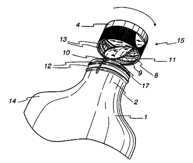
FIG. 1 is a front elevational view of a container
and cap in accordance with a first embodiment of the
invention, shown partially in section, with the cover
lid in open position.
FIG. 2 is a perspective view of the container and
cap of FIG. 1, shown with the cover lid in closed
position, the liner having been partially removed from
the container cap automatically by the opening of the
container.
FIG. 3 is a perspective view of the container and
cap of FIG. 1, showing the liner being held by a user
after having been removed from the container by an
automatic tearing of the liner around the circumference
of the liner when the user opened the container.
FIG. 4 is a top view of a liner which has a tear
member arranged so as to provide a tearing of the liner
around the circumference of the liner.
FIG. 5 is a top view of a liner which has a tear
member arranged so as to provide both diametric and
circumferential tearing of the liner.
FIG. 6 is a top view of a liner which has a tear
member arranged so as to provide a tearing of the liner
in a straight, but off-center, line across the liner,
and along a portion of the circumference.
FIG. 7 also shows a top view of a liner which has a
tear member arranged so as to provide diametric tearing
of the liner in a straight line across the center of the
liner.
CA 02261416 1999-02-09
_...
_g_
DETAILED DESCRIPTION OF THE PREFERRED EMBODIMENTS
The present invention provides a container cap for
use with a container with means for attaching the
container cap to the container comprising a base cap
having a dispensing orifice therein, a movable cover lid
on the base cap, a means for connecting the cover lid to
the base cap, a removable liner which is adhered to the
underside of the base cap, and which extends across the
dispensing orifice prior to its removal, and a tear
member secured to the liner.
In a first embodiment, the tear member is secured
to the container so as to automatically fracture the
liner when the cap is removed. In a second embodiment,
the tear member has a pull tab which protrudes from the
liner so that it can be gripped from the inside of the
base cap portion of the container cap (the part of the
base cap which faces, and attaches to, a container).
The tear member may be arranged so as to enable
tearing of the liner across the liner from one side of
the base cap to the other side of the base cap when a
pulling force is applied to the pull tab.
Alternatively, the tear member may be arranged so as to
enable tearing of the liner around the circumference of
the liner when a pulling force is applied to the pull
tab.
Specific containers and container caps within the
scope of the invention include, but are not limited to,
the containers and container caps discussed in detail
herein and/or illustrated in the drawings contained
herein.
Contemplated equivalents of the containers and
container caps described herein and/or illustrated in
the drawings contained herein include containers and
container caps which otherwise correspond thereto, and
which have the same general properties and/or components
thereof, wherein one or more simple or other variations
of components or materials are made.
CA 02261416 1999-02-09
-10-
For the purpose of illustrating the containers and
container caps of the present invention, there are shown
in the drawings, which form a material part of this
disclosure, several different liners which may be
employed in the containers and container caps of the
invention, and one of the preferred embodiments of the
invention.
The various components of the containers and
container caps of the preferred embodiments may be
generally arranged in the manner shown in the drawings,
or described hereinbelow. However, the present
invention is not limited to the precise arrangements,
configurations, dimensions and/or instrumentalities
shown in these drawings, or described hereinbelow.
These arrangements, configurations, dimensions and
instrumentalities may be otherwise, as circumstances
require.
Different specific embodiments of the containers
and container caps of the present invention will now be
described with reference to the drawings.
Referring to FIGS. 1-3, there is shown a container
cap 15 having a base cap 3, which has a dispensing
orifice 5 present therein for dispensing the contents of
a container 1 therethrough, and a cover lid 4 for
closing the dispensing orifice 5.
The cover lid 4 preferably is detachably connected
to the base cap 3 by a hinge 7, which may comprise a
pivotal connection or a flexible, bendable strip of
material, and may contain an optional cylindrical or
other insert 6 for insertion into the dispensing orifice
5. The insert 6 functions as a plug to close off the
dispensing orifice 5 once a liner 8 has been removed
from the container 1 or container cap 15, and when the
cover lid 4 is in a closed position. The cover lid 4 is
movable about the hinge 7 between a closed position
covering the dispensing orifice 5, with the insert 6
plugging the dispensing orifice 5, and an open
CA 02261416 1999-02-09
-11-
dispensing position, with the insert 6 being removed
from the dispensing orifice 5. In other embodiments of
the invention, the cover lid 4 may be connected with the
base cap 3 by other means, or may be separable from the
base cap 3 without any permanent connection.
The base cap 3 has an outer skirt 11 and internal
threads 13 which are present on the inside of the base
cap 3, and which are complementary to threads 12 on the
outside of the neck 2 of the container 1. These
complementary threads allow the container cap 15 to be
screwed onto the container 1.
The container 1 comprises a bottle which has a rim
17 to which an easily-removable, tamper-evident liner 8
may be secured, and a mouth 16 through which the
contents of the container 1 may flow. The container 1
may also have shoulders 14 which are broader than the
neck 2.
The liner 8 may be adhered to the rim 17 of the
container, or to the underside of the base cap 3. In
both cases, the liner 8 completely seals th,e dispensing
orifice 5, and must be fractured or removed, in order
for the contents of the container 1 to pour through the
dispensing orifice 5. By viewing the absence, or
condition, of this liner 8, a user will be able to
determine whether or not the container 1 has been
tampered with. Further, no knife or other tool need be
employed to remove this liner 8 from the container cap
15, or from the mouth 16 of the container.
As is shown in FIG. 2, the liner 8 has a tear
member 9 which is either secured to the surface of the
liner 8, or is embedded within the liner 8.
As is shown in FIGS. 4-7, a pull tab 10 resulting
from a free end section of the tear member 9, and which
is positioned at the end of the tear member 9, or which
is adjacent to one end of the tear member 9, projects
from the liner 8, and, in certain embodiments of the
invention, allows the user to grip the pull tab 10 and
CA 02261416 1999-02-09
8
-12-
pull it in the appropriate direction (straight across a
diameter of the liner 8 for tear members 9 which are
arranged across a diameter of the liner 8, and around
the circumference of the liner 8 for tear member 9 which
are arranged around the circumference of the liner 8).
In the most preferred embodiments of the invention,
the pull tab 10 will be automatically pulled when the
container cap 15 is unscrewed from, or otherwise removed
from, the container 1, thereby either pulling the tear
member 9 in a straight line diametrically or otherwise
across the liner 8, such that the liner 8 is split into
two pieces of the same or differing sizes, or pulling
the tear member 9 around the circumference of the liner
8, so that all of the liner 8, with the exception of the
portion of the liner 8 which is adhered to the container
1, or to the container cap 15 (FIGS. 2 and 3), will be
removed. Thus, the user need not pull the pull tab 10
in order to remove the liner 8 from the container 1 or
from the container cap 15. In these embodiments of the
invention, when the liner 8 is attached to the container
cap 15, the pull tab 10 will be attached to the threads
12 on the neck 2 of the container 1 (or to the rim 17 or
any other desirable area of the container 1).
Alternatively, when the liner 8 is attached to the rim
17 of the container, the pull tab 10 will be attached to
the internal threads 13 in the base cap 3 portion of the
container cap 15 (or to any other part of the container
cap 15).
As is shown in FIGS. 5-7, the tear member 9 may be
arranged in a manner that it will be pulled in a
straight line diametrically or otherwise across the
liner 8, thereby splitting the liner 8 into two pieces
of the same or differing sizes. As is shown in FIG. 4,
the tear member 9 may, alternatively, be arranged around
the circumference of the liner 8, so that all of the
liner 8, with the exception of the portion of the liner
8 which is adhered to the container 1, or to the
CA 02261416 1999-02-09 _
-13-
container cap 15, will be removed from the container 1
or container cap 15 when the tear member 9 is pulled.
In this case, the tear member 9 will preferably be
offset from the edge of the liner 8 by from about .03 to
about .06 inches. The tear member 9 acts as a knife,
and facilitates the removal of the liner 8 by cutting as
it is either peeled across the center, or across any
area offset from the center, of the liner 8, or is
peeled around the circumference of the liner 8.
Container
The container 1 may be of any desired or convenient
size. For example, the container 1 may be of a size
which holds 12, 16 or 36 ounces of pourable salad
dressing.
The container 1 may be of any desired shape, e.g.,
a shape which is suitable for commercial use with salad
dressings, ketchups, barbecue sauces and other similar
viscous food items. The illustrated container 1 has a
somewhat narrow neck area 2, with broad shoulders 14
which lead to a main body. In one embodiment, the mouth
16 of the container may be, for example, about 1 and 3/8
inches in diameter.
The container 1 may be made of materials such as
glass, plastics, or laminates such as paperboard lined
with foil, or other materials.
In those embodiments of the present invention in
which the liner 8 is secured to the rim 17 of the
container, and across the mouth 16 of the container 1,
the mouth 16 of the container will be closed off from
the outside environment by the liner 8.
Container Cap
The container cap 15 may be of any convenient size,
but should be of a size which fits appropriately with
the container 1. In one embodiment, for example, the
CA 02261416 1999-02-09
-14-
container cap 15 may be about 3/4 inch in height and
about 1 and 5/8 inch in diameter.
While the shape of the container cap 15 is not
critical, the container cap 15 is preferably generally
cylindrical in shape. However, other shapes may also be
possible.
A band of plastic, paper or other material may,
optionally, be adhered to the container 1 and container
cap 15 at the place where the container cap 15 meets
with the container 1 once the container cap 15 has been
screwed onto the container 1 to provide an additional
means of tamper indication.
The container cap 15 is preferably injection molded
with commercially-available materials such as
polypropylene, polyethylene, polystyrene, or other
plastics.
Liner
When the liner 8 is attached to the container cap
15, the size and shape of the liner 8 will generally be
the size and shape of the circumference of the underside
of the base cap 3, which is within the outer skirt 11 of
the container cap 15, so that the liner 8 fits with the
underside of the base cap 3, with its edges touching the
inner portion of the outer skirt 11. When the liner 8
is attached to the container 1, the size and shape of
the liner 8 will generally be the size and shape of the
portion of the container 1 which includes the mouth 16
and rim 17 of the container.
The liner 8 may be made of any material which is
suitable for preventing the contents of the container
from pouring through the dispensing orifice 5, such as
plastic, paper, paperboard, foil or cardboard. The
liner 8 may contain one or more layers of material.
Preferably, the liner 8 is made of an induction-sealable
laminate of a thermoplastic material and a foil
CA 02261416 1999-02-09
-15-
material, which provides a hermetic seal to the contents
of the container 1.
The liner 8 may be attached to the rim 17 of the
container 1, or to the underside of the base cap 3, by
pressure, adhesives, chemical bonding, gluing or heat
sealing and, preferably, by induction sealing, with the
pull tab 10 extending from the tear member 9. When the
liner 8 is adhered to the container cap 15, the liner 8
is preferably sealed to the base cap 3 about its
periphery by induction sealing or other heating methods.
Tear Member
The tear member 9 may be, for example, a plastic,
copper or steel wire, or a nylon, silk, foil or thin
metal tear ribbon, thread, tab, strip, string or tape
which is secured to the liner 8 in any suitable manner,
such as by chemical bonding, gluing or heat sealing with
the use of a sealant coating. However, because
induction sealing equipment is not compatible with
metal, when the liner 8 is attached to the rim 17 of the
container 1, or to the underside of the base cap 3, by
induction sealing, the tear member 9 should not be made
of metal.
The tear member 9 may be securely attached to the
bottom of the liner 8 (the side of the liner 8 which
faces the contents of the container 1), or may be
embedded within the liner 8, or may be integrally molded
with the liner 8, with the pull tab 10 extending from
the tear member 9. Preferably, the tear member 9 is a
heat-resistant tape which has been reinforced with
polymer additives to assure that delamination does not
occur within the structure of the tape, and which has a
tensile strength which is sufficient to prevent it from
breaking when it is pulled.
CA 02261416 1999-02-09
-16-
Operation
In those embodiments of the invention in which the
pull tab must be pulled by the user in order to remove
the liner from the container cap (i.e., when the pull
tab is not automatically pulled when the container cap
is unscrewed from the container), the user may perform
the following steps: (1) lift the cover lid of the
container cap to inspect the liner; (2) unscrew or
otherwise remove the container cap from the container;
(3) grip the pull tab which is present inside the base
cap of the container cap and pull it until the liner is
either split into two pieces, or until the liner becomes
removed; (4) peel the two pieces of the liner off from
the container cap (only where the tear member was
arranged to split the liner); (5) screw or otherwise
secure the container cap back onto the container; (6)
pour a portion of the contents of the container through
the dispensing orifice; and (7) close the cover lid.
In those embodiments of the invention in which the
pull tab need not be pulled by the user, the user will
generally perform the following steps: (1) lift the
cover lid to inspect the liner; (2) unscrew or otherwise
remove the container cap from the container; (3)
manually remove the two pieces of the liner from the
container or cap (only where the tear member was
arranged to split the liner); (4) screw or otherwise
place the container cap back onto the container; (5)
pour a portion of the contents of the container through
the dispensing orifice; and (6) close the cover lid.
Assembly
The container caps and containers of the present
invention are preferably mass produced.
In those embodiments of the invention in which the
liner is attached to the underside of the base cap
portion of the container cap, the tear member is
attached to the bottom of the liner, or is embedded
CA 02261416 1999-02-09
-17-
within the liner, in the manner described hereinabove.
The liner containing the tear member and pull tab
arranged in the desired manner is then attached to the
injection-molded base cap in the manner described
hereinabove. Containers which have passed through a
filler, and which have been filled with the desired
material, pass through a capping machine which applies
the container caps to the containers in a manner such
that the pull tabs extending from the tear members
either remain free to be pulled by the user, or are
connected to threads which are present on the necks of
the containers, or to other desired areas of the
containers, so that they will be automatically pulled
when the container caps are removed from the containers.
In those embodiments of the invention in which the
liner is attached to the rim of the container, the
above-described liner may be carried within the
container cap, and sealed during the application of the
container cap. A packer passes filled containers under
a roller which applies an adhesive to the rim of the
container. The container with adhesive on the rim
passes through a capping machine which applies the screw
cap to the container and presses the liner in the
container cap against the rim of the container. The
high pressure or heat applied bonds the liner through
the adhesive to the rim of the container. When the
container cap is removed, the bonded liner remains on
the rim of the container. The container caps will be
applied to the containers such that the pull tabs
extending from the tear members are connected to the
internal threads present in the container caps, or to
other desired areas of the container caps, so that they
will be automatically pulled when the container caps are
removed from the containers.
Although certain preferred embodiments of the
containers and container caps of the present invention
have been shown and described herein, those of ordinary
CA 02261416 1999-02-09
-."~
Y
-18-
skill in the art will recognize numerous variations,
modifications and substitutions of that which has been
described herein which may be made therein, as by
adding, combining, subdividing parts or steps, or by
substituting equivalents, while retaining significant
advantages of the containers and container caps of the
present invention, which are defined in the following
claims. It is intended, therefore, that all of these
modifications, variations and substitutions be within
the scope and spirit of the present invention as
described and claimed herein, and that the invention be
limited only by the scope of the claims which follow,
and that such claims be interpreted as broadly as
possible.