Note: Descriptions are shown in the official language in which they were submitted.
CA 02261487 1999-02-12
SHOOTING POT ACTUATOR FOR AN INJECTION MOLDING MACHINE
FIELD OF THE INVENTION
The present invention relates to injection molding machines. More
particularly, the present invention relates to the common control of multiple
shooting pots
in a injection molding machine.
BACKGROUND OF THE INVENTION
Employing control units, such as shooting pots, to introduce thermoplastic
resins or other materials into a mold cavity in an injection molding machine
is well
known. Generally, a primary resin source feeds the material to a shooting pot
reservoir
which is, in turn, operated to feed a measured, or metered, quantity of the
material into the
mold cavity. U.S. Patents No. 3,516,123, entitled "Injection Molding Machine",
to Lang;
and No. 3,231,656, entitled "Apparatus and Method of Plastic Molding", to
Ninneman
both disclose the use of shooting pots to provide accurately metered shots of
resin to a
mold cavity. Metering permits an accurate amount of material to be injected
into a mold
to ensure that a properly formed part is created and to prevent waste of
material in the
form of "flash", etc. due to overfilled molds. Metering is generally achieved
by
controlling the distance by which an injection plunger in the shooting pot is
retracted and
advanced for each shot.
Other metering techniques are also well known. For example, U.S. Patent
No. 4,966,545, entitled "Staged Shooting Pot for Injection Molding, to Brown,
shows
how a single shooting pot can be operated to cause two sequential metered
injections of
the same resin into the same mold cavity. U.S. Patent No. 4,460,324, to Van
Appledorn,
entitled "Shot Cylinder Controller for Die Casting Machines and the Like",
shows how
the injection speed of the piston of shooting pot can be controlled, thereby
controlling the
rate of injection of the resin into the mold cavity.
CA 02261487 1999-02-12
-2-
It is also well known to supply thermoplastic material to a multicavity
mold through a hot runner system. The hot runner system can include a
plurality of
shooting pots, with at least one shooting pot associated with each mold
cavity.
Hot runners systems can also be used for multimaterial injection, or
coinjection, molding. Typically, two or more resins are injected, either
simultaneously or
sequentially, into each mold cavity to produce mufti-layered molded
structures. For
example, a common application for multimaterial molding is the production of
food
quality containers from recycled plastic. Government standards require that
any surfaces
which contact the food be made of new, virgin, plastic. To take advantage of
lower cost
recycled plastics, manufacturers use coinjection techniques to encapsulate
recycled
material in a sheath of new plastic. U.S. Patent No. 5,098,274 to
Krishnakumar, entitled
"Apparatus for Injection Molding of Multilayer Preforms", and U.S. Patent No.
4,717,324
to Schad, entitled "Coinjection of Hollow Articles and Preforms" both disclose
injection
molding machines for multimaterial applications.
Generally, individual control of the shooting pot strokes is provided in
these prior art injection molding machines. Separate hydraulic actuation
cylinders for
each shooting pot injection plunger are mounted inside the machine's
stationary platen.
These hydraulic cylinders must be individually set for stroke to control the
individual
metering of the resins into the mold cavities. The setting of the cylinders
can be a
hazardous operation, which is performed manually and requires personnel to
reach into
the machine amongst the heated injection nozzles, close to hot surfaces and
heated
injection materials. Furthermore, the molding process has to be interrupted
for this
adjustment, which can cause significant loss of production time, especially in
larger
machines having up to ninety six injection plungers.
U.S. Patent No. 4,632,653 to Plocher, entitled "Press with a Plurality of
Injection Plungers" describes a common actuator for the injection plungers in
a transfer
molding machine. The injection plungers are actuated by a hydraulic drive
acting on a
single crosspiece. However, the shooting pot actuator disclosed in Plocher has
several
limitations and disadvantages which make it inapplicable to metered injection
molding
CA 02261487 1999-02-12
-3-
machines. Firstly, the shooting pots in a compression molding machine do not
provide
metered shots. Instead, each shooting pot is filled with an approximate amount
of resin,
and the injection pistons are actuated by the crosspiece to compress the resin
into the
mold cavity. Plocher discloses pressure compensating pistons and overflow
channels to
relieve the mold cavities in the case of overfilling, which results in non-
uniform product
and flashing. Also, there is no mechanism provided for adjusting the stroke of
the
injection pistons since precise control of the amount of resin injected into
the mold is not
critical in such a transfer molding process. Second, the crosspiece actuator
in Plocher is
located within the mold, which increases the cost of designing and
manufacturing the
mold. Also, such a design is impractical in machines with high clamp forces as
the
volume occupied by the crosspiece reduces the strength of the mold component
in which
it is located, thus increasing the likelihood of deformation of mold
components when
clamped. Further, the mold must be completely disassembled to obtain access
for
maintenance, adjustment, or replacement.
SUMMARY OF THE INVENTION
It is an object of the present invention to provide a novel shooting pot
actuator for a multicavity injection molding machine which obviates or
mitigates at least
one of the disadvantages of the prior art.
In a first embodiment of the present invention, there is provided an
injection molding machine comprising:
a clamp unit for clamping a mold having at least two shooting pots each having
an
injection plunger, said clamp unit including a stationary platen and a movable
platen
disposed on opposing sides of said mold;
an injection unit to provide to said shooting pots material to be injected;
a shooting pot actuator, exterior to said clamping unit and extending through
one
of said platens; and
a drive means operable to move said actuator between a first position and a
second
position, wherein in said first position said injection plungers limit the
volume of material
which each said shooting pot can receive from said injection unit, and wherein
said
CA 02261487 1999-02-12
-4-
material is expressed from said shooting pots as said actuator is moved to
said second
position.
In a further aspect of the present invention there is provided a
multimaterial injection molding machine comprising:
a mold having at least two mold cavities, each of said at least two mold
cavity
having at least a first and a second shooting pot communicating therewith,
said first and
second shooting pots having respective first and second injection plungers;
a clamp unit including a stationary platen and a movable platen disposed on
opposing sides of said mold;
an injection unit to provide to said shooting pots material to be injected;
a shooting pot actuator, exterior to said clamping unit and extending through
one
of said platens; said actuator having a first group of pushers for abutting
said first
injection plungers, and a second group of pushers for abutting said second
injection
plungers; and
a drive means operable to move said first and second groups of pushers between
a
first position and a second position, wherein in said first position said
injection plungers
limit the volume of material which each said shooting pot can receive from
said injection
unit, and wherein said material is expressed from said shooting pots as said
actuator is
moved to said second position.
In another aspect of the present invention, there is provided a shooting pot
actuation assembly for an injection molding machine having a clamp unit for
clamping a
mold having at least two shooting pots each having an injection plunger, said
clamp unit
including a stationary platen and a movable platen disposed on opposing sides
of said
mold, and an injection unit to provide to said shooting pots material to be
injected,
comprising:
a frame securable to an exterior of one of said platens and having a portion
spaced
from said platen;
a shooting pot actuator, supported for linear movement within said frame, for
extension through said platen to abut said injection plungers; and
CA 02261487 1999-02-12
-5-
a drive mounted on said portion, said drive means being operable to move said
actuator between a first position and a second position, wherein said first
position
determines the volume of material which each said shooting pot can receive
from said
injection unit, and wherein said volume is expressed from said shooting pots
as said
actuator is moved to said second position.
In a further embodiment of the present invention, there is provided a
shooting pot actuator for a multimaterial injection molding machine having a
clamp unit
including a stationary platen and a movable platen disposed on opposing sides
of a mold
having at least two mold cavities and at least first and second shooting pots
for each said
mold cavity, said shooting pots having corresponding first and second
injection plungers,
and an injection unit to provide to said shooting pots material to be
injected, comprising:
at least two first pushers, each said first pusher operable to abut a
respective first
injection plunger; and
at least two second pushers through which said first pushers extend, each said
second pusher operable to abut a respective second injection plunger;
said first and second pushers operable to move independently between a first
and
second position wherein said first position determines the volume of material
which each
respective shooting pot can receive from said injection unit, and wherein said
volume is
expressed from said shooting pots as said pushers are moved to said second
position.
BRIEF DESCRIPTION OF THE DRAWINGS
Preferred embodiments of the present invention will now be described, by
way of example only, with reference to the attached Figures, wherein:
Fig. 1 is a schematic illustration of a multimaterial hot runner system for a
four cavity mold;
Fig. 2 shows a cross section of a multimaterial hot runner system in the
vicinity of one nozzle assembly;
Fig. 3 shows a cross section of a portion multimaterial injection molding
machine, including a common shooting pot actuation assembly with all pushers
in the
retracted position;
CA 02261487 1999-02-12
-6-
Fig. 4 shows a rear view of the machine of Fig. 3 in the direction of the
line D;
Fig. 5 shows a cross section of the machine of Fig. 3 along the line A-A;
Fig. 6 shows a cross section of the machine of Fig. 3 along the line B-B;
and
Fig. 7 shows a cross section of the machine of Fig. 3 along the line C-C.
Fig. 8 shows the machine of Fig. 3 with the first set of pushers advanced;
Fig. 9 shows the machine of Fig. 3 with both the first and second sets of
pushers advanced;
DETAILED DESCRIPTION
For purposes of illustration, the present invention will be described with
reference to a dual hot runner injection molding machine as shown in the
drawings. As
will be apparent to those skilled in the art, the present invention can be
generally
employed in any injection molding machines having multiple shooting pots for
which
common control is desired.
An embodiment of the present invention is shown in Figs. 1 and 2,
wherein Fig. 1 shows a shows a schematic and Fig. 2 shows a cross section of a
portion of
a hot runner system for an injection molding machine which accommodates two
thermoplastic resins, or other material to be molded, indicated generally at
reference
numeral 20. One resin is provided from a source identified as Extruder A, the
other resin
is provided form a source identified as Extruder B. While the illustrated
embodiment
shows two resin sources A and B, it is entirely within the scope of the
invention to utilize
one, two or more sources. The portion of the hot runner system 20 leading from
Extruder
A is shown in solid lines, and the portion of the system leading from Extruder
B is shown
in dashed lines.
As shown in Fig. 1, the materials supplied by Extruders A and B are fed to
mold cavities 22, 24, 26 and 28 through corresponding individual coinjection
nozzles 32,
34, 36 and 38. Extruder A supplies a heated manifold Ma which, in turn,
communicates
with each nozzle 32, 34, 36 and 38 via hot runners or channels 42, 44, 46 and
48,
CA 02261487 1999-02-12
_7_
respectively. Rotary valves 52, 54, 56 and 58 operate to control charging of
shooting
pots, or injection cylinders, 62, 64, 66 and 68.
Correspondingly, heated manifold Mb leads from Extruder B to each
nozzle 32, 34, 36 and 38 via hot runners 72, 74, 76 and 78. Rotary valves 82,
84, 86 and
88 control charging of shooting pots 92, 94, 96 and 98.
While the schematic of Fig. 1 shows a hot runner system 20 leading from
two sources, Extruders A and B, transporting conditioned thermoplastic resins
to a four
cavity mold, it is entirely within the scope of the present invention to
service forty-eight,
or more, mold cavities originating from one, two or more sources.
As shown in Fig. 2, a central manifold block 102 is maintained at an
appropriate temperature range by heating elements 104. For example, if the
resin is
polyethylene terephthalate (PET), the central manifold block can be maintained
at a
temperature ranging from approximately 500° to 550° F. Channels
106 and 108 receive
plasticized resin from Extruder A. Rotary valve 112, in circuit with channel
108 and
operated by link mechanism 114, controls the charging of reservoir 116 of
shooting pot,
or injection cylinder, 118 each of which is equipped with an injection plunger
122.
Rotary valve 112 is formed with a transverse throughbore 124 and is shown in
Fig. 2 in
the closed position. The reservoir 116 communicates with channel 126 which, in
turn,
leads to the nozzle assembly 32. Nozzle assembly 32 functions to inject the
resin into a
mold cavity (not shown).
Similarly, for the path leading from Extruder B, a manifold block 130,
which can be a separate segment from manifold 102 or a part thereof, is
maintained at an
appropriate temperature range by heating elements 132. For example, if the
resin is
ethylene vinyl alcohol copolymer (EVOH), the central manifold block can be
maintained
at a temperature ranging from approximately 400° to 440° F by
heaters 132. Channels 134
receives plasticized resin from Extruder B. Rotary valve 144, in circuit with
channel 134
and operated by link mechanism 133, controls the charging of reservoir 136 of
shooting
pot, or injection cylinder, 138 each of which is equipped with an injection
plunger 142.
CA 02261487 2004-03-23
g
Rotary valve 144 is formed with a transverse throughbore 146 and is shown in
Fig. 2 in the
closed position. The reservoir 136 communicates with channel 140 which, in
turn, leads to
the nozzle assembly 32.
Nozzle assembly 32 includes a central spigot 146 in thermal contact with
manifold block 102. Spigot 146 is formed with a through channel 148 through
which the
resin can flow to a nozzle gate 152. As shown, a valve stem 166 moved by an a
piston 164
controls the opening and closing of gate 152. Other gating systems, as are
well known to
those of skill in the art can be used to control the injection of resin
through nozzle assembly
32.
Spigot 146 is supported by minimal bearing surfaces in a housing 158 which
is spaced from spigot 146 substantially through its length by an insulating
air gap 162 to
maintain the resin from Extruder B at its optimum processing temperature as it
progresses to
gate 152 through a channel 160.
Generally, to inj ect the two resins from Extruders A and B into each mold
1 S cavity, the set of injection plungers 122 for the resin supplied by
Extruder A is first advanced
to displace a metered amount of the first resin into the mold cavity,
partially filling it. This is
followed by advancing injection plunger 142 to displace a metered amount of
the second
resin supplied by Extruder B, again only partially filling the mold cavity.
Finally, a second
feeding of the first resin directly through channel 126, bypassing shooting
pot 118, fills the
mold cavity and packs out the molded articles. As is well understood, the
particular
sequence chosen for producing the molded articles will depend on the desired
final structure,
and can include simultaneous, as well as sequential, injection into the mold
cavity.
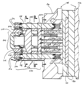
Figs. 3 - 9 show side and rear views of an injection molding machine
incorporating an embodiment of the present invention. In Fig. 3, a mold 180,
shown in
dashed lines and including hot runner system 20, is mounted between a clamp
unit 184.
Clamp unit 184 generally comprises a stationary platen 190 and a movable
platen 192.
Mounted to the exterior of the stationary platen 190 is a common shooting pot
actuation
CA 02261487 1999-02-12
-9-
assembly 196. While in the illustrated embodiment, and the following
description of the
present invention, the shooting pot actuation assembly 196 is mounted to the
stationary
platen 190, it is fully within the contemplation of the inventors that
assembly 196 can be
mounted to movable platen 192.
Shooting pot actuation assembly 196 generally comprises a frame 198, a
shooting pot actuator 200, and drive means 202. Frame 198 has four columns
204, 206,
208 and 210 secured to stationary platen 190 in a generally rectilinear
pattern, as best seen
in Fig. 4, by bolts 212. A drive support 214, spaced from the rear of the
stationary platen
190 by the exposed length of columns 204, 206, 208 and 210 is mounted to the
ends of
the columns and secured by bolts 216. To drive support 214 are attached first
and second
drives 218 and 220, the operation of which will be further described below.
Drives 218
and 220 can be hydraulic rams, linear electric motors, or any other suitable
drive.
Shooting pot actuator 200 is mounted on columns 204, 206, 208 and 210
for sliding movement between drive support 214 and the rear of stationary
platen 190. In
the illustrated embodiment, actuator 200 has two parallel and separately
movable plates
222 and 224. A first group of pushers 226 is secured to first plate 222.
Pushers 226 are
arranged to correspond to the position of each of the injection plungers 142
in their
respective set in mold 180. Similarly, a second group of pushers 228 are
secured to
second plate 224, and are arranged to correspond to the position of injection
plungers 122
in their respective set. Pushers 226 and 228 can be screwed into plates 222
and 224, or
can be secured with "bayonet" mounts, or in any other appropriate manner.
Ideally, the
mounting method ensures that each mounted pusher 226, 228 extends from its
respective
plate 222, 224 to a substantially identical extent.
Pushers 226 and 228 extend through bores 230 and 232, respectively, in
stationary platen 190 and abut injection pistons 142 and 122. The arrangement
of pushers
226 and 228 depends upon the placement of shooting pots 138 and 118, and their
respective injection plungers 142 and 122, in the hot runner system 20. Fig. 7
shows an
arrangement suitable for a forty-eight mold cavity coinjection molding machine
for
making preforms. To accommodate a number of different shooting pot
arrangements,
CA 02261487 1999-02-12
-10-
pushers 226 and 228 can be detached and rearranged as desired on plates 222
and 224, or,
separate plate-pusher assemblies can be provided for different molds 180. It
is
contemplated that standardized injection plunger spacings can be employed to
permit
molds to be interchangeable, as described below in more detail.
Plate 222 can be driven reciprocally along columns 204, 206, 208 and 210
by corresponding drive 218. As best seen in Figs. 5 and 6, drive 218 comprises
two
hydraulic cylinder pistons 234. Plate 224 is similarly driven by drive 220
which
comprises two hydraulic cylinder pistons 236. Since plate 222 is disposed in
front of
plate 224, piston bores 238 are provided in plate 222 to accommodate the
passage of
pistons 236 and to permit free movement of plate 222 with respect to plate
224.
Similarly, bores 239 are provided in plate 22 to permit the free passage of
pushers 228
therethrough. Depending on the configuration of pistons 236, bores 238 and 239
can be
replaced by cutouts, or omitted altogether if the pushers would not interfere.
The position and linear velocity of plates 222 and 224 can be sensed by
linear position sensor means 240. Sensor 240 can be a magnetic, opto-
electronic or other
suitable sensor, such as those manufactured by Temposonic Inc. Sensor 240 is
fixed to
frame 198, or otherwise fixed relative to plates 222 and 224. The sensor 240
can be
attached to a suitable control system (not shown) for conventional electronic
and/or
programmable control of the actuator 200, as is well known to those of skill
in the art.
Referring to Figs. 3, 8 and 9, the operation of the actuator 200 will be
described with respect a multimaterial injection sequence. Prior to the below
described
injection sequence, the clamp unit 184 is activated to clamp together the mold
180, in a
manner well understood by those of skill in the art. The injection sequence
begins with
pushers 226 and 228, and plates 222 and 224, in a retracted position, as shown
in Fig. 3.
In the retracted position, the free ends of the pushers 226 and 228, which
abut the
injection pistons 142 and 122 in the hot runner system 20, limit the rearward
movement
of the injection pistons 142 and 122, and, hence the volume of material that
can be
received in shooting pot reservoirs 136 and 116. Adjusting the retracted
positions of
plates 222 and 224, by adjusting the rearward stroke of their respective
cylinder pistons
CA 02261487 1999-02-12
-11-
234 and 236, thereby effectively meters the amount of material can be accepted
by each
shooting pot 138 and 118 from Extruders B and A.
Once the shooting pots 138 and 118 are filled with the desired amount of
material in the manner described above, plate 224 and its pushers 228 are
advanced to
actuate the set of injection pistons 122, thereby injecting the metered shot
of material
from each reservoir 116 into its respective mold cavity. Pushers 228 are
advanced by a
forward stroke of cylinder pistons 236 acting upon plate 224 in the direction
of the arrow
F, as shown in Fig. 8. Bores 238 and 239 permit plate 222 to move forward
without
affecting the position of plate 222. The position and speed of plate 224
during the forward
stroke is sensed by sensor 240. Sensor 240 relays the information to the
control system
which, in turn, controls the speed and distance travelled by the pushers 228.
Next, as shown in Fig. 9, plate 222 and its pushers 226 are advanced to
actuate injection plungers 142, thereby injecting the metered shot of material
from each
reservoir 136 into its respective mold cavity. Pushers 226 are advanced by a
forward
stroke of cylinder pistons 234 acting upon plate 222 in the direction of the
arrow G. The
position and speed of plate 222 are sensed by sensor 240 to control the speed
and distance
travelled by the pushers 226, as described above. An injection of material
from Extruder
A is then fed directly to the nozzle 32 to pack the mold, and the gate 152 is
closed.
The coinjection molding operation then proceeds as in conventional
machines. The material injected into the mold cavities is permitted to cool,
the clamp unit
184 is released, and the finished product is ejected from the mold.
As will be apparent to those skilled in the art, the present invention not
limited to two plates, but can extended to three or more plates-pushers and
corresponding
sets of shooting pots, as desired. Nor is the actuator of the present
invention limited to
sequential injection of the multiple resins. Combinations of sequential and/or
simultaneous movement of the push rods are possible to cause like injections
of the
respective resins.
CA 02261487 2004-03-23
-12-
The actuator assembly 196 of the present invention can also be
incorporated into a transfer molding system, as described in U.S. Patent
Number
6,152,721 issued November 28, 2000. As described therein, the injection
plungers are
pulled backwards from their forward stroke position at the same rate as the
shooting pots
are being filled to reduce the acetaldehyde content of the finished articles.
In this case, to
incorporate the actuator assembly 196, the pusher rods 226, 228 are fixed to
the injection
plungers to permit the controlled retraction of the injection pistons, and a
control system
monitors and controls the rate at which the plungers are pulled backwards.
The provision of a single actuation assembly 196 for a plurality of
shooting pots, exterior to the mold 180 and clamp unit 194 has clear
advantages over the
prior art. The actuation of a group of shooting pots in a mold can be effected
by a single
adjustment to the speed and distance travelled by its related plate and
respective pushers.
This adjustment can be accomplished "on the fly" and/or can be automatically
controlled
by the control system in response to the information detected by the linear
position
sensor. This eliminates hazardous, individual manual adjustments, and lengthy
interruptions and delays in production while ensuring the supply of accurately
metered
materials. The stroke of each plate, and the arrangement of the pushers on
each plate can
also be independently adjusted.
The fact that the actuator is outside the mold can reduce the cost of
constructing an injection molding machine by providing a much simpler
structure and
reducing the number of costly hydraulic components and circuitry required for
individual
shooting pot actuation. For example, the significant reduction in numbers of
hydraulic
cylinders and valuing from ninety-six in a typical forty-eight cavity
coinjection molding
machine, to just four cylinders and their corresponding valuing can result in
significant
cost reductions. The cost of operation and maintenance can also be reduced
because of
simpler construction. In particular, hydraulic cylinders and piping within the
stationary
platen can be eliminated, fewer, more robust cylinders can be employed, and
access to the
cylinders for maintenance and adjustment is simplified.
CA 02261487 1999-02-12
-13-
The present invention also provides increased design flexibility to the
designers of molds and production lines. Extra plates can be easily added to
the actuator
to handle additional resin injections. Also relocating pusher rods to match
different
shooting pot arrangements is easy to facilitate. Drilling a different bore
pattern in the
plates and stationary platen is much less costly than having to relocate the
multiple
actuation cylinders within the stationary platen of the prior art. The design
of molds is
also greatly simplified by eliminating the need for multiple cylinders within
the stationary
platen, and the cost of the molds is therefore reduced.
The ability to add/detach pushers and rearrange them on their respective
plates can also reduce the time and cost associated with re-tooling an
injection molding
machine. Generally, the detachable nature of the pushers permits new pusher
arrangements to be easily effected for any given mold design. Pushers of
different
lengths, shapes and sizes can interchanged on the same plate, as is
appropriate for each
particular mold design. It is contemplated that molds can be designed with
standardized
shooting pot spacings. For example, if a mold having twenty-four mold cavities
at eight
inch spacings is to be replaced by a mold having twelve cavities at sixteen
inch spacings,
every second pusher can be removed to arrive at the appropriate arrangement.
The actuator of the present invention can also greatly reduce the time
required to set, or re-program, the stroke cycle for a particular mold or
product. The cycle
only has to be set for each set of like shooting pots, not for each separate
shooting pot.
Information relating to the stroke control for a particular mold can be
stored, by electronic
or other means, which allows the rapid changing of molds. This can be
especially useful
for "short run" molds.
Locating the actuator outside the mold also permits shooting pots in the
hot runner to be repositioned to optimize resin flow channels and shorten flow
lengths.
Prior art actuators imposed limitations on the shooting pot layout by virtue
of the space
required in the stationary platen to accommodate the hydraulic actuation
cylinders and
their associating valuing and plumbing. By removing this limitation more
efficient hot
CA 02261487 1999-02-12
- 14-
runner designs are possible and resin management can be optimized, thereby
reducing the
resin inventory within a machine.
The above-described embodiments of the invention are intended to be
examples of the present invention and alterations and modifications may be
effected
thereto, by those of skill in the art, without departing from the scope of the
invention
which is defined solely by the claims appended hereto