Language selection

Search

Patent 2261523 Summary

Third-party information liability

Some of the information on this Web page has been provided by external sources. The Government of Canada is not responsible for the accuracy, reliability or currency of the information supplied by external sources. Users wishing to rely upon this information should consult directly with the source of the information. Content provided by external sources is not subject to official languages, privacy and accessibility requirements.

Claims and Abstract availability

Any discrepancies in the text and image of the Claims and Abstract are due to differing posting times. Text of the Claims and Abstract are posted:

  • At the time the application is open to public inspection;
  • At the time of issue of the patent (grant).
(12) Patent: (11) CA 2261523
(54) English Title: CAB ENCLOSURE FOR A SELF-PROPELLED EARTH MOVING MACHINE
(54) French Title: CABINE POUR MACHINE DE TERRASSEMENT AUTOMOTRICE
Status: Expired
Bibliographic Data
(51) International Patent Classification (IPC):
  • E02F 9/16 (2006.01)
  • B62D 33/06 (2006.01)
  • E02F 5/16 (2006.01)
(72) Inventors :
  • FLEMING, JEFFERY WILLIAM THOMAS (Canada)
(73) Owners :
  • FLEMING, JEFFERY WILLIAM THOMAS (Canada)
(71) Applicants :
  • FLEMING, JEFFERY WILLIAM THOMAS (Canada)
(74) Agent: WOODRUFF, NATHAN V.
(74) Associate agent:
(45) Issued: 2005-11-01
(22) Filed Date: 1999-02-12
(41) Open to Public Inspection: 2000-08-12
Examination requested: 2003-02-07
Availability of licence: N/A
(25) Language of filing: English

Patent Cooperation Treaty (PCT): No

(30) Application Priority Data: None

Abstracts

English Abstract

A cab enclosure for a self-propelled earth moving machine which includes a plurality of flexible planar fabric panels namely, a front panel, a rear panel, a right side panel and a left side panel. Each of the panels having a top edge, a bottom edge, opposed side edges, and at least one transparent viewing window. Mating fasteners are positioned along the opposed edges of each of the panels, whereby adjoining panels are secured together to form an enclosure. The top edge of each of the panels being secured to a canopy of an open metallic cab structure of the self-propelled earth moving machine, whereby the panels hang like drapes to enclose the cab.


French Abstract

La présente invention concerne une enceinte de cabine pour machine de terrassement automotrice qui comprend une pluralité de panneaux d'un tissu plan souple à savoir, un panneau avant, un panneau arrière, un panneau latéral droit et un panneau latéral gauche. Chacun des panneaux a un bord supérieur, un bord inférieur, des bords latéraux opposés et au moins une fenêtre transparente. Des fixations en accouplement sont positionnées le long des bords opposés de chacun des panneaux, attachant ainsi ensemble les panneaux adjacents pour former une enceinte. Le bord supérieur de chacun des panneaux est attaché à un toit d'une structure de cabine métallique ouverte de la machine de terrassement automotrice, duquel les panneaux pendent comme des rideaux pour fermer la cabine.

Claims

Note: Claims are shown in the official language in which they were submitted.


6

THE EMBODIMENTS OF THE INVENTION IN WHICH AN EXCLUSIVE
PROPERTY OR PRIVILEGE IS CLAIMED ARE DEFINED AS FOLLOWS:

1. A cab enclosure for self-propelled earth moving machine,
comprising in combination:
the self-propelled earth moving machine having a
metallic superstructure with an open cab having an overlying
protective roof canopy held up by columns spaced at intervals
about a periphery of the roof canopy with open spaces between
the columns, the open cab only occupying a portion of the
overlying protective roof canopy;
a plurality of flexible planar fabric panels including a
front panel, a rear panel, a left side panel, and a right
side panel, each of the plurality of panels having a top
edge, a bottom edge, opposed side edges, and at least one
transparent viewing window;
fasteners along the opposed edges of each of the
plurality of panels, whereby adjoining panels are secured
together;
magnets along the top edge and the bottom edge of each
of the plurality of panels;
the top edge of each of the front panel, the rear panel,
the left side panel and the right side panel being secured by
the magnets to the roof canopy and hanging like drapes to
surround and enclose only the portion of the roof canopy that
overlies the open cab;
the bottom edge of each of the front panel, the rear
panel, the left side panel and the right side panel being
secured by the magnets to the superstructure.

Description

Note: Descriptions are shown in the official language in which they were submitted.


CA 02261523 2003-08-07
r
1
TITLE OF THE INVENTION:
Cab Enclosure for a Self-propelled Earth Moving Machine
NAME ( S ) OF INVENTOR ( S )
Jeffery William Thomas Fleming
FIELD OF THE INVENTION
The present invention relates to a cab enclosure for a
self-propelled earth moving machine, such as a bulldozer or
any other open canopy crawler tractor.
BACKGROUND OF THE INVENTION
Most bulldozers have open canopy cabs that expose the
equipment operator to the elements. The operator is exposed
to the cold of winter, the mosquitos of summer and the winds
of spring and fall. As a result, there are often times when
it is not pleasant operating a bulldozer. Bulldozers can be
purchased with closed cabs, but they are relatively rare and
more expensive. The most common cab structure consists of a
protective roof held up by columns spaced at intervals about
the periphery of the roof. The spaces between the columns
are open. This provides the operator with good visibility,
but also exposes the operator to the elements.
SUMMARY OF THE INVENTION
What is required is a cab enclosure that can be readily
installed to retrofit a self-propelled earth moving machine
to enclose the canopy cab.
According to the present invention there is provided a
cab enclosure for a self-propelled earth moving machine which
includes a plurality of flexible planar fabric panels. Each
of the panels having a top edge, a bottom edge, opposed side
edges, and at least one transparent viewing window. Mating
fasteners are positioned along the opposed edges of each of
the panels, whereby adjoining panels are secured together to
form an enclosure. The top edge of each of the panels being

a
CA 02261523 2003-08-07
2
secured to a canopy of an open metallic cab structure of the
self-propelled earth moving machine, whereby the panels hang
like drapes to enclose the cab.
BRIEF DESCRIPTION OF THE DRAWINGS
These and other features of the invention will become
more apparent from the following description in which
reference is made to the appended drawings, wherein:
FIGURE 1 labelled as PRIOR ART is side elevation view of
a bulldozer.
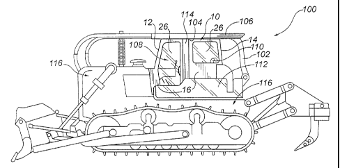
FIGURE 2 is a side elevation view of the bulldozer
illustrated in FIGURE 1 with cab enclosed by the cab
enclosure of the present invention.
FIGURE 3 is a front elevation view of a front panel of
the cab enclosure illustrated in FIGURE 2.
FIGURE 4 is a rear elevation view of a rear panel of the
cab enclosure illustrated in FIGURE 2.
FIGURE 5 is a side elevation view of a side panel of the
cab enclosure illustrated in FIGURE 2.
FIGURE 6 is a top plan view of a top panel of the cab
enclosure illustrated in FIGURE 2.
FIGURE 7 is a detailed side elevation view of a side
panel of the cab enclosure illustrated in FIGURE 2.
FIGURE 8 is an exploded perspective view of the side
panel portion of the cab enclosure illustrated in FIGURE 2.
FIGURE 9 is top plan view of the front panel, rear
panel, left side panel, right side panel and top panel
assembled to form the cab enclosure before installation.
DETAILED DESCRIPTION OF THE PREFERRED E1~ODIMENT
The preferred embodiment, a cab enclosure generally
identified by reference numeral 10, will now be described
with reference to FIGURES 1 through 9.
Referring to FIGURE 1, a self-propelled earth moving
machine such as a bulldozer 100 includes an open metallic cab

1
CA 02261523 2003-08-07
3
structure 102 set upon a superstructure 116 of bulldozer 100.
Open metallic cab 102 has a metallic canopy or roof structure
106. Canopy 106 is supported by substantially vertical
columns or support members 114 that extend upward from
superstructure 116 and a substantially horizontal beam 104
spanning between the opposed sides of open metallic cab 102.
Roof structure 106 extends over a front section 108 of the
cab area and a driver's seat 110. In the absence of a
protective enclosure, a driver seated in driving seat 110 is
unprotected from dust, mosquitos and inclement weather such
as cold, high winds, or precipitation, except for such
minimal protection afforded by low metallic side panels 112.
Referring to FIGURES 3 through 6, cab enclosure 10 for a
self-propelled earth moving machine includes a plurality of
flexible planar fabric panels as will now be described.
Referring to FIGURE 3. there is a front panel 12. Referring
to FIGURE 4, there is a rear panel 14. Referring to FIGURE
5. there is a mirror image pair of side panels 16. Referring
to FIGURE 6. there is a top panel 18 that is optionally
attached, as will subsequently be described, below canopy 106
of open metallic cab structure 102. Referring to FIGURES 3
through 5, each of the front panel 12, rear panel 14, and
side panels 16 has a top edge 20, a bottom edge 22, opposed
side edges 24, and at least one transparent viewing window
26. Windows 26 can, optionally, have cover flaps or screens.
Referring to FIGURE 5. a notch 27 is provided in top edge 20
of each of side panels 16 to allow side panels 16 to be
fitted under beam 104 of open metallic cab structure 102.
Referring to FIGURE 6~ top panel 18 has a peripheral edge 29
comprising a front portion 28, a rear portion 30, and opposed
side portions 31. Top panel 18 is substantially planar
except where said top panel 18 has a recessed portion 33 to
fit around beam 104 of open metallic cab structure 102.
Referring to FIGURES 3 through 5, a plurality of zippers 34
serve as mating fasteners along opposed edges 24 of each of

CA 02261523 2003-08-07
4
the adjoining panels 12, 14, and 16, whereby said adjoining
panels 12, 14, and 16 are secured together to form an
enclosure. Referring to FIGURE 3. front panel 12 is foldable
at positions indicated by dotted lines 35 so that front panel
12 can enclose fully the front section 108 of open metallic
cab structure 102. Referring to FIGURE 6, peripheral edge 29
of top panel 18 has a matching plurality of zippers 34 that
serve as fasteners that mate with the corresponding zippers
34 on top edges 20 of front panel 12, rear panel 14, and side
panels 16.
Referring to FIGURE 7, in which one of mirror pair of
side panels 16 is shown for purposes of illustration, a
plurality of magnets 32 is spaced along top edges 20 and
bottom edges 22 of each of front panel 12, rear panel 14, and
side panels 16. Referring to FIGURE 8, in which only side
panel 16 is shown for purposes of illustration, magnets 39
are secured to top panel 12, rear panel 14, and side panels
16 as will now be described. Each magnet 34 is secured into
position by a bolt 40 that passes through fabric 41, through
a hole 42 in magnet 32, and through a washer 44, and is
secured in position by a nut 46. In this manner, magnets 32
are secured in position to exterior surface 48 of fabric 41
along top edge 20 and bottom edge 22. Where a top panel 18 is
used, it can function with our without magnets. When used
without magnets, top panel 18 is held up by being secured to
the other panels and relying upon the holding force of
magnets 32 from the other panels. Where top panel 18 is used
with magnets, magnets 32 are secured around perimeter 29 of
top panel 18 in the same manner as described with the other
panels.
The method of use of cab enclosure 10 will now be
described with reference to FIGURES 1 through 8. Referring
to FIGURE 7, magnets are secured in a spaced arrangement
adjacent to top edges 20 and bottom edges 22 of each of front
panel 12, illustrated in FIGURE 3, rear panel 14, illustrated

CA 02261523 2003-08-07
in FIGURE 4, and side panels 16, illustrated in FIGURE 5.
Referring to FIGURE 8, magnets 32 along top edges 20 of front
panel 12, rear panel 14, and side panels 16 are each
magnetically secured to canopy 106, thereby securing said
5 panels in a substantially vertical orientation so that they
hang like drapes enclosing the cab. Optionally, magnets 32
along bottom edges 22 of front panel 12, rear panel 14 and
side panels 16 are magnetically secured to superstructure 116
of bulldozer 100, to side panels 112 or to some other lower
portion of open metallic cab structure 102. Referring to
FIGURE 2, front panel 12, rear panel 14, and side panels 16
are secured to each other by zippers 34 to form an enclosure
within said cab structure 102. Top panel 18, illustrated in
FIGURE 6. can optionally be secured to front panel 12, rear
panel 14, and side panels 16 by zippers 34.
Referring to FIGURE 9~ when it is possible for some
models of equipment to have cab enclosure constructed as an
integral unit 50, top edges 20 of each of panels 12, 14, and
16 are mated to corresponding portions 28, 30, and 32 of
peripheral edge of top panel 18 by a seam indicated by a
dashed line 36. An integral unit 50 so constructed is
secured within open metallic cab structure 102 in a similar
manner to that described above for individual front panel 12,
rear panel 14, side panels 16, and top panel 18 of cab
enclosure 10.
It will be apparent to one skilled in the art that
modifications may be made to the illustrated embodiment
without departing from the spirit and scope of the invention
as hereinafter defined in the Claims.

Representative Drawing
A single figure which represents the drawing illustrating the invention.
Administrative Status

For a clearer understanding of the status of the application/patent presented on this page, the site Disclaimer , as well as the definitions for Patent , Administrative Status , Maintenance Fee  and Payment History  should be consulted.

Administrative Status

Title Date
Forecasted Issue Date 2005-11-01
(22) Filed 1999-02-12
(41) Open to Public Inspection 2000-08-12
Examination Requested 2003-02-07
(45) Issued 2005-11-01
Expired 2019-02-12

Abandonment History

There is no abandonment history.

Payment History

Fee Type Anniversary Year Due Date Amount Paid Paid Date
Application Fee $150.00 1999-02-12
Maintenance Fee - Application - New Act 2 2001-02-12 $50.00 2001-01-24
Maintenance Fee - Application - New Act 3 2002-02-12 $50.00 2002-02-04
Request for Examination $200.00 2003-02-07
Maintenance Fee - Application - New Act 4 2003-02-12 $50.00 2003-02-07
Maintenance Fee - Application - New Act 5 2004-02-12 $100.00 2004-02-09
Maintenance Fee - Application - New Act 6 2005-02-14 $100.00 2005-02-07
Final Fee $150.00 2005-08-05
Maintenance Fee - Patent - New Act 7 2006-02-13 $100.00 2006-01-06
Maintenance Fee - Patent - New Act 8 2007-02-12 $100.00 2007-01-12
Maintenance Fee - Patent - New Act 9 2008-02-12 $100.00 2008-01-07
Maintenance Fee - Patent - New Act 10 2009-02-12 $125.00 2009-02-09
Maintenance Fee - Patent - New Act 11 2010-02-12 $125.00 2010-02-09
Maintenance Fee - Patent - New Act 12 2011-02-14 $125.00 2011-02-11
Maintenance Fee - Patent - New Act 13 2012-02-13 $125.00 2012-02-07
Maintenance Fee - Patent - New Act 14 2013-02-12 $125.00 2013-02-12
Maintenance Fee - Patent - New Act 15 2014-02-12 $225.00 2014-01-15
Maintenance Fee - Patent - New Act 16 2015-02-12 $225.00 2015-02-04
Maintenance Fee - Patent - New Act 17 2016-02-12 $225.00 2016-02-12
Maintenance Fee - Patent - New Act 18 2017-02-13 $225.00 2017-02-07
Maintenance Fee - Patent - New Act 19 2018-02-12 $225.00 2018-02-09
Owners on Record

Note: Records showing the ownership history in alphabetical order.

Current Owners on Record
FLEMING, JEFFERY WILLIAM THOMAS
Past Owners on Record
None
Past Owners that do not appear in the "Owners on Record" listing will appear in other documentation within the application.
Documents

To view selected files, please enter reCAPTCHA code :


To view images, click a link in the Document Description column. To download the documents, select one or more checkboxes in the first column and then click the "Download Selected in PDF format (Zip Archive)" or the "Download Selected as Single PDF" button.

List of published and non-published patent-specific documents on the CPD .

If you have any difficulty accessing content, you can call the Client Service Centre at 1-866-997-1936 or send them an e-mail at CIPO Client Service Centre.


Document
Description 
Date
(yyyy-mm-dd) 
Number of pages   Size of Image (KB) 
Representative Drawing 2000-08-09 1 14
Abstract 2003-08-07 1 21
Description 2003-08-07 5 247
Claims 2003-08-07 1 40
Drawings 2003-08-07 7 181
Abstract 1999-02-12 1 18
Description 1999-02-12 5 239
Claims 1999-02-12 4 120
Drawings 1999-02-12 7 109
Cover Page 2000-08-09 1 38
Representative Drawing 2005-10-07 1 17
Cover Page 2005-10-07 1 45
Correspondence 2011-03-31 3 154
Assignment 1999-02-12 2 71
Prosecution-Amendment 2003-02-07 1 38
Prosecution-Amendment 2003-02-07 1 36
Prosecution-Amendment 2003-08-07 17 564
Fees 2004-02-09 1 30
Fees 2005-02-07 1 26
Correspondence 2005-08-05 1 26
Fees 2006-01-06 1 26
Fees 2007-01-12 1 25
Correspondence 2007-11-16 5 123
Correspondence 2007-12-27 1 15
Correspondence 2007-12-19 1 12
Correspondence 2008-01-07 2 67
Fees 2008-01-07 2 67
Fees 2009-02-09 1 30
Fees 2010-02-09 1 201
Fees 2011-02-11 1 201
Correspondence 2011-05-31 1 11
Correspondence 2011-05-31 1 19
Fees 2015-02-04 1 33