Language selection

Search

Patent 2261583 Summary

Third-party information liability

Some of the information on this Web page has been provided by external sources. The Government of Canada is not responsible for the accuracy, reliability or currency of the information supplied by external sources. Users wishing to rely upon this information should consult directly with the source of the information. Content provided by external sources is not subject to official languages, privacy and accessibility requirements.

Claims and Abstract availability

Any discrepancies in the text and image of the Claims and Abstract are due to differing posting times. Text of the Claims and Abstract are posted:

  • At the time the application is open to public inspection;
  • At the time of issue of the patent (grant).
(12) Patent Application: (11) CA 2261583
(54) English Title: DEVICE FOR TUNING A MICROWAVE SYSTEM
(54) French Title: DISPOSITIF POUR ACCORDER UN SYSTEME A HYPERFREQUENCE
Status: Dead
Bibliographic Data
(51) International Patent Classification (IPC):
  • H01F 5/04 (2006.01)
  • H01P 5/04 (2006.01)
(72) Inventors :
  • ARNOLD, WOLFGANG (Germany)
  • PIVIT, ERICH (Germany)
  • GRELL, HANS-MICHAEL (Germany)
(73) Owners :
  • ARNOLD, WOLFGANG (Not Available)
  • PIVIT, ERICH (Not Available)
  • GRELL, HANS-MICHAEL (Not Available)
(71) Applicants :
  • AFT ADVANCED FERRITE TECHNOLOGY GMBH (Germany)
(74) Agent: FETHERSTONHAUGH & CO.
(74) Associate agent:
(45) Issued:
(86) PCT Filing Date: 1997-07-07
(87) Open to Public Inspection: 1998-02-05
Availability of licence: N/A
(25) Language of filing: English

Patent Cooperation Treaty (PCT): Yes
(86) PCT Filing Number: PCT/DE1997/001463
(87) International Publication Number: WO1998/005086
(85) National Entry: 1999-01-20

(30) Application Priority Data:
Application No. Country/Territory Date
196 29 864.4 Germany 1996-07-24
196 34 416.6 Germany 1996-08-26

Abstracts

English Abstract


A tuning device which allows the fast periodical frequency tuning of a
microwave system with simple mechanical means consists of one or several
tuning elements (2, 3) which project into a wave guide (1) and are mounted to
rotate around an axis (4) perpendicular to the longitudinal axis of the wave
guide.


French Abstract

L'invention concerne un dispositif d'accord, permettant, avec un mécanisme peu complexe, de modifier rapidement l'accord des fréquences d'un système à hyperfréquence. Ce dispositif comprend un ou plusieurs éléments d'accord (2, 3) faisant saillie à l'intérieur d'un guide d'ondes (1), lesdits éléments étant montés de façon à pouvoir tourner autour d'un axe (4) perpendiculaire à l'axe longitudinal du guide d'ondes.

Claims

Note: Claims are shown in the official language in which they were submitted.


Claims

1. An apparatus for tuning the frequency of a magnetron,
characterized in that at least one tuning element (2,3), which
acts inductively or capacitively, is so arranged in a hollow
waveguide (1) that is connected to the magnetron (11) that it
affects the frequency of the magnetron (11); and in that at least
one tuning element (2,3) is supported so as to be rotatable about
an axis (4) that is oriented so as to be perpendicular to the
longitudinal axis of the hollow waveguide, so that incremental
frequency tuning of the magnetron (11) results.


2. An apparatus as defined in Claim 1, characterized in
that one or a plurality of tuning elements (2,3,5) are arranged
on a disk (7) that is supported so as to be rotatable in a wall
of the hollow waveguide.


3. An apparatus as defined in Claim 1 or Claim 2,
characterized in that a plurality of disks with tuning elements
are supported so as to be rotatable within one or more of the
walls of the hollow waveguide.

-8-


4. An apparatus as defined in Claim 2 or Claim 3,
characterized in that an annular collar (10) on the disk (7) and
an annular collar (9) that is mounted on the wall of the hollow
waveguide and encircles the disk (7) form a choke; and in that
both collars (9,10) are of a height that is approximately equal
to one-quarter the wavelength of the hollow waveguide.


5. An apparatus as defined in one of the preceding claims,
characterized in that apart from the rotatably supported tuning
element(s) (2,3,5) at least one fixed tuning element (6) extends
into the hollow waveguide (1)

-9-

Description

Note: Descriptions are shown in the official language in which they were submitted.


CA 02261~83 1999-01-20

_ ., _ ~ . . . . .
. ~
__
PCT/DE97/01463


Apparatus for Tuning the Frequency of a Magnetron


There are times when it is necessary to periodically tune
the frequency of a microwave system incrementally. Using the
tuning elements that have been referred to, the penetration depth
of which can be varied, this is made possible only by using a
very costly drive system. Moreover, this means that no high
adjustment speeds can be achieved. A microwave system with which
frequency tuning is meant to be carried out at a very small
period (approximately 50 ms) is a magnetron, which is used to
heat substances in a microwave oven. The lossy dielectric
properties of the substances that are to be heated convert the
microwave energy into heat. Since such a microwave oven is a
resonator in which many wave modes are excitable, an electrical
field configuration with locally fixed maxima and minima is
formed when the resonator is excited with a specific frequency.
The resulting thermal energy conforms to this field image and
forms locally fixed hot and cold areas. Thus, it is impossibl~
to achieve even heating of the substance in the microwave oven.
This disadvantage can be avoided in that the frequency of the
magnetron is varied. As the frequency changes, so does the
configuration of the field within the oven, i.e., the hot and
cold areas shift. This makes more even heat distribution within


--1--
28840-3

CA 02261~83 1999-01-20


PCT/DE97/01463


the oven possible. The frequency of the magnetron is best tuned
periodically, with a period duration of the frequency tuning of
approximately 50 ms being desirable.
EP O 344 438 describes a microwave oven to which the
electromagnetic field generated by a magnetron is connected
through a hollow waveguide. In order to arrive at the most even
possible distribution of energy density within the oven, a so-
called field agitator is arranged within the hollow waveguide.
This agitator is arranged relative to the connection opening in
the hollow waveguide and in the oven so that it affects the field
that is introduced into the oven in such a way that even
distribution of the energy density results.
GB 681 801 A and DE 10 02 053 C describe hollow waveguide
tuning devices in the form of disks that incorporate an eccentric
1() stub and are supported within the wall of the hollow waveguide so
as to be rotatable.
It is the objective of the present invention to describe an
apparatus that requires the least costly mechanical drive syst~m
in order to complete incremental frequency tuning of a magnetron
l~ that changes very rapidly on a periodic basis.
According to the present invention, this objective has been
achieved by the features set out in Patent Claim 1. According to
this, the penetration depth of one or more tuning elements is not


28840-3


T ~-

CA 02261~83 1999-01-20


PCT/DE97/01463


changed for incremental frequency tuning; rather, the location of
the tuning element(s) is changed by rotating them about an axis
that is perpendicular to the longitudinal axis of a hollow
waveguide that is connected to the magnetron. Such rotation can
be executed are very high speed, with very little wear, by a
simple motor drive.
As set out in the secondary claims, it is advantageous to
arrange the tuning elements on one or a plurality of rotatable
disks. In order to avoid interruption of the hollow waveguide
wall currents to the rotating disks, it is expedient to arrange a
choke connection between the disks and the walls of the hollow
waveguide.
The present invention will be described in greater detail on
the basis of several exemplary embodiments shown in the drawings
l~ appended hereto. These drawings show the following:


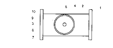
Figure 1: a longitudinal cross section through a hollow waveguide
with a rotatable tuning device;
Figure 2: a plan view of this hollow waveguide, in direction A;
~~ Figure 3: a longitudinal cross section through a hollow waveguide
with a rotatable inductive loop;
Figure 4: A Rike diagram.


28840-3

CA 0226l~83 l999-0l-20


PCT/DE97/01463

Figure 1 shows a longitudinal cross section through a hollow
waveguide 1 that is connected, for example, to a magnetron 11 in
order to tune the frequency of this periodically. To this end,
within the hollow waveguide 1 there are two stubs 2 and 3 as
tuning elements, and these are supported so as to be able to
rotate about a axis 4 that is oriented so as to be perpendicular
to the longitudinal axis of the hollow waveguide. By rotating
the stubs 2 and 3, which are spaced apart from the axis of
rotation by a distance that is approximately one-quarter the
lo wavelength of the hollow waveguide, their phase effect is changed
from capacitive to inductive. In addition, as well as the phase,
the amount of the reflection factor also changes, since the
distance of the stubs 2 and 3 from the centre of the waveguide
also changes.
1~ Unlike the embodiment shown in Figure 1, instead of the
two stubs 2 and 3 it is possible to rotate either a single stub
or more than two stubs. In the same way, as is shown in Figure
3, in place of capacitive stubs, one or a plurality of inductive
loops 5 can be rotated about the axis 4 within the hollow
2~ waveguide 1. The number of tuning elements, the type of these
(stubs or loops) and their distance from the axis of rotation
will be determined according to which variation of the phase and
the amount of the reflection factor that is to be achieved.


28840-3

CA 02261~83 1999-01-20


PCT/DE97/01463


One or more fixed tuning elements 6 can also be
installed in the hollow waveguide in addition to the rotatable
tuning elements. Because of the interaction of the rotating
tuning element(s) 2,3,5 relative to the fixed tuning element(s)
6, the total reflection factor traces a curve in the Smith
diagram that can be approximated to a desired curve by suitable
dimensioning of the tuning elements and by their spacing relative
to each other.
As can be seen from the longitudinal cross sections
through the hollow waveguide l shown in Figures 1 and 3 and the
plan view of the hollow waveguide, in direction A, shown in
Figure 2, the tuning elements 2,3,5 are arranged on a circular
disk 7 that is supported so as to be able to rotate within the
hollow waveguide wall. The disk 7 is mounted on a drive shaft 8
l~ by which the disk 7 can be rotated by means of a motor. The disk
7 is supported in such a way in an opening in a wall of the
hollow waveguide that it is free of contact. In order to avoid
interruption of the hollow waveguide wall currents to the
rotating disk 7, a collar 9 is installed on the wall of the
hollow waveguide at the edge of the opening, and in the same way,
a collar 10 is installed on the edge of the disk 7. Both collars
g and 10 are of a height that is approximately that of one-
quarter of the wavelength ~ and form a choke, i.e., the open


28840-3

CA 02261~83 1999-01-20


PCT/DE97/01463


circuit at the upper end of the gap between the two collars 9 and
10 is transformed into a short circuit at the lower end (in the
wall of the hollow waveguide).
A plurality of rotating disks with one or more tuning
S elements can also be used in the hollow waveguide.
As has already been discussed, the tuning device that
has been described can be connected to a magnetron 11 in order to
adjust its frequency on a periodic basis. In order to tune the
frequency of a magnetron it is possible to use the fact that the
frequency and the output power of a magnetron are dependent on
the value of the load resistance, which can be adjusted by means
of the tuning device. This dependency is illustrated in the Rike
diagram that is shown in Figure 4. The Rike diagram shows the
frequency and power behaviour of a magnetron that is connected to
1~ different load resistances of various reflection factors. On
connection with the characteristic impedance (mid-point of the
diagram), the maximum power (> 12kW) will be at the frequency f0.
The constant-power curves are arranged elliptically around the~
mid-point. The dashed lines are constant-frequency curves. The
2() hashed area represents the prohibited zone. If the magnetron is
operated with reflection factors within this prohibited zone,
mode shifts that could result is its destruction may occur within
the magnetron. If a magnetron is to be tuned periodically over a


28840-3

CA 02261~83 1999-01-20


PCT/DE97/01463


wide range of frequencies, without any notable loss of output
power, the reflection factor of the terminal resistance can-, for
example, conform to the power curve for 11.5 kW, from the left-
hand limit of the prohibited zone as far as the right-hand limit,
along the constant-power curve and back.


28840-3

Representative Drawing
A single figure which represents the drawing illustrating the invention.
Administrative Status

For a clearer understanding of the status of the application/patent presented on this page, the site Disclaimer , as well as the definitions for Patent , Administrative Status , Maintenance Fee  and Payment History  should be consulted.

Administrative Status

Title Date
Forecasted Issue Date Unavailable
(86) PCT Filing Date 1997-07-07
(87) PCT Publication Date 1998-02-05
(85) National Entry 1999-01-20
Dead Application 2001-04-24

Abandonment History

Abandonment Date Reason Reinstatement Date
2000-04-25 FAILURE TO RESPOND TO OFFICE LETTER
2000-07-07 FAILURE TO PAY APPLICATION MAINTENANCE FEE

Payment History

Fee Type Anniversary Year Due Date Amount Paid Paid Date
Application Fee $150.00 1999-01-20
Maintenance Fee - Application - New Act 2 1999-07-07 $50.00 1999-04-22
Owners on Record

Note: Records showing the ownership history in alphabetical order.

Current Owners on Record
ARNOLD, WOLFGANG
PIVIT, ERICH
GRELL, HANS-MICHAEL
Past Owners on Record
None
Past Owners that do not appear in the "Owners on Record" listing will appear in other documentation within the application.
Documents

To view selected files, please enter reCAPTCHA code :


To view images, click a link in the Document Description column. To download the documents, select one or more checkboxes in the first column and then click the "Download Selected in PDF format (Zip Archive)" or the "Download Selected as Single PDF" button.

List of published and non-published patent-specific documents on the CPD .

If you have any difficulty accessing content, you can call the Client Service Centre at 1-866-997-1936 or send them an e-mail at CIPO Client Service Centre.


Document
Description 
Date
(yyyy-mm-dd) 
Number of pages   Size of Image (KB) 
Representative Drawing 1999-04-12 1 3
Abstract 1999-01-20 1 48
Description 1999-01-20 7 233
Claims 1999-01-20 2 47
Drawings 1999-01-20 2 37
Cover Page 1999-04-12 1 32
Claims 1999-02-11 2 50
Assignment 1999-01-20 3 95
Correspondence 1999-03-23 1 30
PCT 1999-01-20 20 704
Prosecution-Amendment 1999-02-11 3 72