Sélection de la langue

Search

Sommaire du brevet 2261583 

Énoncé de désistement de responsabilité concernant l'information provenant de tiers

Une partie des informations de ce site Web a été fournie par des sources externes. Le gouvernement du Canada n'assume aucune responsabilité concernant la précision, l'actualité ou la fiabilité des informations fournies par les sources externes. Les utilisateurs qui désirent employer cette information devraient consulter directement la source des informations. Le contenu fourni par les sources externes n'est pas assujetti aux exigences sur les langues officielles, la protection des renseignements personnels et l'accessibilité.

Disponibilité de l'Abrégé et des Revendications

L'apparition de différences dans le texte et l'image des Revendications et de l'Abrégé dépend du moment auquel le document est publié. Les textes des Revendications et de l'Abrégé sont affichés :

  • lorsque la demande peut être examinée par le public;
  • lorsque le brevet est émis (délivrance).
(12) Demande de brevet: (11) CA 2261583
(54) Titre français: DISPOSITIF POUR ACCORDER UN SYSTEME A HYPERFREQUENCE
(54) Titre anglais: DEVICE FOR TUNING A MICROWAVE SYSTEM
Statut: Réputée abandonnée et au-delà du délai pour le rétablissement - en attente de la réponse à l’avis de communication rejetée
Données bibliographiques
(51) Classification internationale des brevets (CIB):
  • H01F 5/04 (2006.01)
  • H01P 5/04 (2006.01)
(72) Inventeurs :
  • ARNOLD, WOLFGANG (Allemagne)
  • PIVIT, ERICH (Allemagne)
  • GRELL, HANS-MICHAEL (Allemagne)
(73) Titulaires :
  • AFT ADVANCED FERRITE TECHNOLOGY GMBH
(71) Demandeurs :
  • AFT ADVANCED FERRITE TECHNOLOGY GMBH (Allemagne)
(74) Agent: SMART & BIGGAR LP
(74) Co-agent:
(45) Délivré:
(86) Date de dépôt PCT: 1997-07-07
(87) Mise à la disponibilité du public: 1998-02-05
Licence disponible: S.O.
Cédé au domaine public: S.O.
(25) Langue des documents déposés: Anglais

Traité de coopération en matière de brevets (PCT): Oui
(86) Numéro de la demande PCT: PCT/DE1997/001463
(87) Numéro de publication internationale PCT: WO 1998005086
(85) Entrée nationale: 1999-01-20

(30) Données de priorité de la demande:
Numéro de la demande Pays / territoire Date
196 29 864.4 (Allemagne) 1996-07-24
196 34 416.6 (Allemagne) 1996-08-26

Abrégés

Abrégé français

L'invention concerne un dispositif d'accord, permettant, avec un mécanisme peu complexe, de modifier rapidement l'accord des fréquences d'un système à hyperfréquence. Ce dispositif comprend un ou plusieurs éléments d'accord (2, 3) faisant saillie à l'intérieur d'un guide d'ondes (1), lesdits éléments étant montés de façon à pouvoir tourner autour d'un axe (4) perpendiculaire à l'axe longitudinal du guide d'ondes.


Abrégé anglais


A tuning device which allows the fast periodical frequency tuning of a
microwave system with simple mechanical means consists of one or several
tuning elements (2, 3) which project into a wave guide (1) and are mounted to
rotate around an axis (4) perpendicular to the longitudinal axis of the wave
guide.

Revendications

Note : Les revendications sont présentées dans la langue officielle dans laquelle elles ont été soumises.


Claims
1. An apparatus for tuning the frequency of a magnetron,
characterized in that at least one tuning element (2,3), which
acts inductively or capacitively, is so arranged in a hollow
waveguide (1) that is connected to the magnetron (11) that it
affects the frequency of the magnetron (11); and in that at least
one tuning element (2,3) is supported so as to be rotatable about
an axis (4) that is oriented so as to be perpendicular to the
longitudinal axis of the hollow waveguide, so that incremental
frequency tuning of the magnetron (11) results.
2. An apparatus as defined in Claim 1, characterized in
that one or a plurality of tuning elements (2,3,5) are arranged
on a disk (7) that is supported so as to be rotatable in a wall
of the hollow waveguide.
3. An apparatus as defined in Claim 1 or Claim 2,
characterized in that a plurality of disks with tuning elements
are supported so as to be rotatable within one or more of the
walls of the hollow waveguide.
-8-

4. An apparatus as defined in Claim 2 or Claim 3,
characterized in that an annular collar (10) on the disk (7) and
an annular collar (9) that is mounted on the wall of the hollow
waveguide and encircles the disk (7) form a choke; and in that
both collars (9,10) are of a height that is approximately equal
to one-quarter the wavelength of the hollow waveguide.
5. An apparatus as defined in one of the preceding claims,
characterized in that apart from the rotatably supported tuning
element(s) (2,3,5) at least one fixed tuning element (6) extends
into the hollow waveguide (1)
-9-

Description

Note : Les descriptions sont présentées dans la langue officielle dans laquelle elles ont été soumises.

CA 02261~83 1999-01-20
_ ., _ ~ . . . . .
. ~
__
PCT/DE97/01463
Apparatus for Tuning the Frequency of a Magnetron
There are times when it is necessary to periodically tune
the frequency of a microwave system incrementally. Using the
tuning elements that have been referred to, the penetration depth
of which can be varied, this is made possible only by using a
very costly drive system. Moreover, this means that no high
adjustment speeds can be achieved. A microwave system with which
frequency tuning is meant to be carried out at a very small
period (approximately 50 ms) is a magnetron, which is used to
heat substances in a microwave oven. The lossy dielectric
properties of the substances that are to be heated convert the
microwave energy into heat. Since such a microwave oven is a
resonator in which many wave modes are excitable, an electrical
field configuration with locally fixed maxima and minima is
formed when the resonator is excited with a specific frequency.
The resulting thermal energy conforms to this field image and
forms locally fixed hot and cold areas. Thus, it is impossibl~
to achieve even heating of the substance in the microwave oven.
This disadvantage can be avoided in that the frequency of the
magnetron is varied. As the frequency changes, so does the
configuration of the field within the oven, i.e., the hot and
cold areas shift. This makes more even heat distribution within
--1--
28840-3

CA 02261~83 1999-01-20
PCT/DE97/01463
the oven possible. The frequency of the magnetron is best tuned
periodically, with a period duration of the frequency tuning of
approximately 50 ms being desirable.
EP O 344 438 describes a microwave oven to which the
electromagnetic field generated by a magnetron is connected
through a hollow waveguide. In order to arrive at the most even
possible distribution of energy density within the oven, a so-
called field agitator is arranged within the hollow waveguide.
This agitator is arranged relative to the connection opening in
the hollow waveguide and in the oven so that it affects the field
that is introduced into the oven in such a way that even
distribution of the energy density results.
GB 681 801 A and DE 10 02 053 C describe hollow waveguide
tuning devices in the form of disks that incorporate an eccentric
1() stub and are supported within the wall of the hollow waveguide so
as to be rotatable.
It is the objective of the present invention to describe an
apparatus that requires the least costly mechanical drive syst~m
in order to complete incremental frequency tuning of a magnetron
l~ that changes very rapidly on a periodic basis.
According to the present invention, this objective has been
achieved by the features set out in Patent Claim 1. According to
this, the penetration depth of one or more tuning elements is not
28840-3
T ~-

CA 02261~83 1999-01-20
PCT/DE97/01463
changed for incremental frequency tuning; rather, the location of
the tuning element(s) is changed by rotating them about an axis
that is perpendicular to the longitudinal axis of a hollow
waveguide that is connected to the magnetron. Such rotation can
be executed are very high speed, with very little wear, by a
simple motor drive.
As set out in the secondary claims, it is advantageous to
arrange the tuning elements on one or a plurality of rotatable
disks. In order to avoid interruption of the hollow waveguide
wall currents to the rotating disks, it is expedient to arrange a
choke connection between the disks and the walls of the hollow
waveguide.
The present invention will be described in greater detail on
the basis of several exemplary embodiments shown in the drawings
l~ appended hereto. These drawings show the following:
Figure 1: a longitudinal cross section through a hollow waveguide
with a rotatable tuning device;
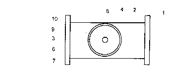
Figure 2: a plan view of this hollow waveguide, in direction A;
~~ Figure 3: a longitudinal cross section through a hollow waveguide
with a rotatable inductive loop;
Figure 4: A Rike diagram.
28840-3

CA 0226l~83 l999-0l-20
PCT/DE97/01463
Figure 1 shows a longitudinal cross section through a hollow
waveguide 1 that is connected, for example, to a magnetron 11 in
order to tune the frequency of this periodically. To this end,
within the hollow waveguide 1 there are two stubs 2 and 3 as
tuning elements, and these are supported so as to be able to
rotate about a axis 4 that is oriented so as to be perpendicular
to the longitudinal axis of the hollow waveguide. By rotating
the stubs 2 and 3, which are spaced apart from the axis of
rotation by a distance that is approximately one-quarter the
lo wavelength of the hollow waveguide, their phase effect is changed
from capacitive to inductive. In addition, as well as the phase,
the amount of the reflection factor also changes, since the
distance of the stubs 2 and 3 from the centre of the waveguide
also changes.
1~ Unlike the embodiment shown in Figure 1, instead of the
two stubs 2 and 3 it is possible to rotate either a single stub
or more than two stubs. In the same way, as is shown in Figure
3, in place of capacitive stubs, one or a plurality of inductive
loops 5 can be rotated about the axis 4 within the hollow
2~ waveguide 1. The number of tuning elements, the type of these
(stubs or loops) and their distance from the axis of rotation
will be determined according to which variation of the phase and
the amount of the reflection factor that is to be achieved.
28840-3

CA 02261~83 1999-01-20
PCT/DE97/01463
One or more fixed tuning elements 6 can also be
installed in the hollow waveguide in addition to the rotatable
tuning elements. Because of the interaction of the rotating
tuning element(s) 2,3,5 relative to the fixed tuning element(s)
6, the total reflection factor traces a curve in the Smith
diagram that can be approximated to a desired curve by suitable
dimensioning of the tuning elements and by their spacing relative
to each other.
As can be seen from the longitudinal cross sections
through the hollow waveguide l shown in Figures 1 and 3 and the
plan view of the hollow waveguide, in direction A, shown in
Figure 2, the tuning elements 2,3,5 are arranged on a circular
disk 7 that is supported so as to be able to rotate within the
hollow waveguide wall. The disk 7 is mounted on a drive shaft 8
l~ by which the disk 7 can be rotated by means of a motor. The disk
7 is supported in such a way in an opening in a wall of the
hollow waveguide that it is free of contact. In order to avoid
interruption of the hollow waveguide wall currents to the
rotating disk 7, a collar 9 is installed on the wall of the
hollow waveguide at the edge of the opening, and in the same way,
a collar 10 is installed on the edge of the disk 7. Both collars
g and 10 are of a height that is approximately that of one-
quarter of the wavelength ~ and form a choke, i.e., the open
28840-3

CA 02261~83 1999-01-20
PCT/DE97/01463
circuit at the upper end of the gap between the two collars 9 and
10 is transformed into a short circuit at the lower end (in the
wall of the hollow waveguide).
A plurality of rotating disks with one or more tuning
S elements can also be used in the hollow waveguide.
As has already been discussed, the tuning device that
has been described can be connected to a magnetron 11 in order to
adjust its frequency on a periodic basis. In order to tune the
frequency of a magnetron it is possible to use the fact that the
frequency and the output power of a magnetron are dependent on
the value of the load resistance, which can be adjusted by means
of the tuning device. This dependency is illustrated in the Rike
diagram that is shown in Figure 4. The Rike diagram shows the
frequency and power behaviour of a magnetron that is connected to
1~ different load resistances of various reflection factors. On
connection with the characteristic impedance (mid-point of the
diagram), the maximum power (> 12kW) will be at the frequency f0.
The constant-power curves are arranged elliptically around the~
mid-point. The dashed lines are constant-frequency curves. The
2() hashed area represents the prohibited zone. If the magnetron is
operated with reflection factors within this prohibited zone,
mode shifts that could result is its destruction may occur within
the magnetron. If a magnetron is to be tuned periodically over a
28840-3

CA 02261~83 1999-01-20
PCT/DE97/01463
wide range of frequencies, without any notable loss of output
power, the reflection factor of the terminal resistance can-, for
example, conform to the power curve for 11.5 kW, from the left-
hand limit of the prohibited zone as far as the right-hand limit,
along the constant-power curve and back.
28840-3

Dessin représentatif
Une figure unique qui représente un dessin illustrant l'invention.
États administratifs

2024-08-01 : Dans le cadre de la transition vers les Brevets de nouvelle génération (BNG), la base de données sur les brevets canadiens (BDBC) contient désormais un Historique d'événement plus détaillé, qui reproduit le Journal des événements de notre nouvelle solution interne.

Veuillez noter que les événements débutant par « Inactive : » se réfèrent à des événements qui ne sont plus utilisés dans notre nouvelle solution interne.

Pour une meilleure compréhension de l'état de la demande ou brevet qui figure sur cette page, la rubrique Mise en garde , et les descriptions de Brevet , Historique d'événement , Taxes périodiques et Historique des paiements devraient être consultées.

Historique d'événement

Description Date
Inactive : CIB de MCD 2006-03-12
Demande non rétablie avant l'échéance 2001-04-24
Inactive : Morte - Aucune rép. à lettre officielle 2001-04-24
Réputée abandonnée - omission de répondre à un avis sur les taxes pour le maintien en état 2000-07-07
Inactive : Renseign. sur l'état - Complets dès date d'ent. journ. 2000-06-02
Inactive : Abandon. - Aucune rép. à lettre officielle 2000-04-25
Symbole de classement modifié 1999-03-29
Inactive : CIB attribuée 1999-03-29
Inactive : CIB en 1re position 1999-03-29
Inactive : Lettre de courtoisie - Preuve 1999-03-23
Inactive : Notice - Entrée phase nat. - Pas de RE 1999-03-16
Demande reçue - PCT 1999-03-12
Modification reçue - modification volontaire 1999-02-11
Demande publiée (accessible au public) 1998-02-05

Historique d'abandonnement

Date d'abandonnement Raison Date de rétablissement
2000-07-07

Taxes périodiques

Le dernier paiement a été reçu le 1999-04-22

Avis : Si le paiement en totalité n'a pas été reçu au plus tard à la date indiquée, une taxe supplémentaire peut être imposée, soit une des taxes suivantes :

  • taxe de rétablissement ;
  • taxe pour paiement en souffrance ; ou
  • taxe additionnelle pour le renversement d'une péremption réputée.

Veuillez vous référer à la page web des taxes sur les brevets de l'OPIC pour voir tous les montants actuels des taxes.

Historique des taxes

Type de taxes Anniversaire Échéance Date payée
Taxe nationale de base - petite 1999-01-20
TM (demande, 2e anniv.) - petite 02 1999-07-07 1999-04-22
Titulaires au dossier

Les titulaires actuels et antérieures au dossier sont affichés en ordre alphabétique.

Titulaires actuels au dossier
AFT ADVANCED FERRITE TECHNOLOGY GMBH
Titulaires antérieures au dossier
ERICH PIVIT
HANS-MICHAEL GRELL
WOLFGANG ARNOLD
Les propriétaires antérieurs qui ne figurent pas dans la liste des « Propriétaires au dossier » apparaîtront dans d'autres documents au dossier.
Documents

Pour visionner les fichiers sélectionnés, entrer le code reCAPTCHA :


Pour visualiser une image, cliquer sur un lien dans la colonne description du document. Pour télécharger l'image (les images), cliquer l'une ou plusieurs cases à cocher dans la première colonne et ensuite cliquer sur le bouton "Télécharger sélection en format PDF (archive Zip)" ou le bouton "Télécharger sélection (en un fichier PDF fusionné)".

Liste des documents de brevet publiés et non publiés sur la BDBC .

Si vous avez des difficultés à accéder au contenu, veuillez communiquer avec le Centre de services à la clientèle au 1-866-997-1936, ou envoyer un courriel au Centre de service à la clientèle de l'OPIC.


Description du
Document 
Date
(aaaa-mm-jj) 
Nombre de pages   Taille de l'image (Ko) 
Abrégé 1999-01-20 1 48
Description 1999-01-20 7 233
Revendications 1999-01-20 2 47
Dessins 1999-01-20 2 37
Page couverture 1999-04-12 1 32
Revendications 1999-02-11 2 50
Dessin représentatif 1999-04-12 1 3
Rappel de taxe de maintien due 1999-03-15 1 111
Avis d'entree dans la phase nationale 1999-03-16 1 193
Demande de preuve ou de transfert manquant 2000-01-24 1 111
Courtoisie - Lettre d'abandon (taxe de maintien en état) 2000-08-07 1 184
Courtoisie - Lettre d'abandon (lettre du bureau) 2000-05-30 1 171
PCT 1999-01-20 20 705
Correspondance 1999-03-23 1 30