Note: Descriptions are shown in the official language in which they were submitted.
CA 02261936 1999-01-22
WO g8/05017 I PCT/US97/13087
EMBEDDED MISSION AVIONICS DATA LINK SYSTEM
OBJECT OF THE INVENTION
This invention relates to a data link for a military aircraft or vehicle, and more
5 specifically to a data link system which receives, transmits, recognizes, prioritizes,
configures, and presents many dir~ t types of information and provides the flight
crew the capability to extend their window of visibility in terms of imagery andprecision data to other platforms.
BA~KGROUND OF THE INVENTION
When a modern military aircraft flies a mission it is oftentimes necessary to fly
in concert with other aircraft. This synchronous flying requires extensive pl~nning of a
route with respect to known threats, satisfactory knowledge of the threat location, and
information on the capabilities of the threat. The mission planning must also include
5 the coordination of activities among the aircraft. In order to execute a complex mission
against a dangerous target, it is important that there are two-way lines of
communications between all the aircraft as well as between the aircraft and a ground
station.
Many modern military aircraft are equipped with a digital map system which
20 displays to the pilot the characteristics of the terrain around the aircraft, the location of
the aircraft relative to the terrain, the flight path of the aircraft, and the location of the
target relative to the aircraft. Other information displayed to the pilot may include the
visibility of the aircraft relative to the target and possible flight paths for the aircraft to
avoid detection by the threat. The disadvantage of a digital map system is that the map
25 image is pre-processed and does not include dynamic elements of real-time mission
scenes.
Currently, military aircraft are limited on the amount of information which is
received and transmitted from other aircraft as well as from a ground station. These
transmissions are mostly limited to voice communications. Limited means also exist to
30 transmit some mission information to an aircraft. As currently configured, the voice
communication and mission updates require two separate systems in order to process
the different types of information. The need to operate two separate systems during a
CA 02261936 1999-01-22
W O 98t05017 2 PCTrUS97/13087
mission can be a burden on the flight crew. A system which provides for greater
transmission and receipt capability of flight and mission information, would only be
desirable in an aircraft data link if the use of these functions did not add significantly to
the workload of the flight crew. The system would have to identify the types of
s information being received, automatically prioritize it, and compile it in a format for the
flight crew to easily access on their in-cockpit display screens.
When a military aircraft is flying a mission within the vicinity of a threat, certain
types of information can increase the likelihood of the success of the mission. The
effectiveness of the flight crew would be enhanced by providing means for the aircraft
0 to cornmunicate in many different modes and provide constant updates of each other's
position as well as other mission related data. There would also be an advantage to
transferring video imagery information between aircraft. One example is where a scout
ship flies on ahead of the rest of the aircraft to perform some kind of recolmaissance on
a target. This scout ship can then transmit back to the other aircraft as well as a ground
station real-time video imagery of the target to provide up to date conditions at the
threat site. Another advantageous feature would be the ability to automatically, without
significant attention from the pilot, transmit updated mission information among the
aircraft as well as to a ground station.
SU M M ARY OF THEIN VENTION
Disclosed herein is a datalink system for a vehicle which increases both missionsituation awareness and capability, and at the same time reduces the workload of the
vehicle crew by providing a variety of automatic functions which identify and prioritize
digitized data which is received and transmitted by the vehicle. The system includes a
2s communications apparatus which provides the vehicle two-way voice and digitized data
communications. A data signal processing apparatus in connection with the
communications apparatus, identifies information received externally by the vehicle,
and provides to the communications apparatus, information which has been generated
internally. A ll~t~link controller directs the processing of the information received
externally and the information generated by the vehicle with the ~l~t~link system. Also
included is a prioritization a~pa~dllls connected to the data signal processing apparatus
which prioritizes the internal information, decodes external information according to the
n ~ ~
CA 02261936 1999-01-22
wO 98/05017 3 PCT/US97/13087
type of mission the vehicle is on, and displays image classification. A memory, which
is accessible by the tl~t~link controller and the data signal processing appdldlus, stores
information generated internally and received externally. A display apl)ald~ls processes
the int~:rn~lly and externally generated information and provides it in the proper format
s to the pilot for viewing. The pilot may annotate the images which appear on the cockpit
displays and either store those annotated image in memory or transmit them externally.
Other objects, features and advantages of the invention will become apparent to
those skilled in the art from the description of the preferred embodiment, claims and
drawings hereof, wherein like numerals refer to like elements.
BRIEF DESCRIPTION OF THE DRAWINGS
Figure 1 is a block diagram of a mission avionics system structure.
Figure 2 is a block diagram of the Embedded Mission Avionics Data Link
System.
Figure 3 is a flow chart of the mission avionics graphic generator.
Figure 4 is a flow chart depicting the operation of the moving map generator.
Figure 5 is a block diagram of the mission avionics data link control.
Figure 6 is a flow chart of the image data annotation process.
Figure 7 is a flow chart of the prioritization and authentication process.
Figure 8 is a flow chart depicting the operation of the set up and control of the
transmit/receive medium.
Figure 9 is a flow chart depicting the operation of the digitize and control of
video image apparatus.
Figure 10a-d is a flow chart depicting the operation of the data signal processing
2s apparatus.
DESCRIPTION OF THE PREFERRED EMBODIMENT
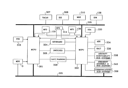
Disclosed in Fig. 1 is a block diagrarn of a mission avionics system structure for
a military aircraft. At the core of the system there are two master controller processor
(MCPU's) units 301 and 302 which process all the information received from pilots as
well as the aircraft systems and sensors. The two MCPU's process input and output
signals for different aircraft systems, and also act as redundant paths for the critical
CA 02261936 1999-01-22
W O 98/05017 PCTrUS97/13087
aircraft functional modules. Although this is not a complete diagram of the avionics
system, all the systems necessary for a description of the present invention arepresented. The sensors and systems input signals to the MCPU's are either received
over the avionics bus 305 or through a direct connection. Transmitting signals on the
avionics bus 305 are communications sub-systems 306, the navigation radio (TACAN)
307, the embedded global positioning and inertial navigation system (EGI) 308, the
mast mounted sight system (MMS) 310 which provides television video and thermal
video images outside the aircraft, and the improved data modem (IDM) 138. The
memory data unit (MDU) 3 is also connected to the avionics bus, but also has a high
0 speed dedicated bus to MCPU 301. The avionics bus disclosed is a well known bus
structurc to those skilled in the art.
In direct connection with the MCPU 301 is the video tape recorder (VTR) 316
which records and plays back events on board the aircraft. In direct contact with MCPU
302 is the optical display assembly (ODA) 330, for night ViSiOII viewing the ANVIS
Display Symbology Subsystem (ADS) 334, and the radar altimeter (RALT) 336. Also
in connection with MCPU 302 are the aircraft survivability subsystems 338 and the
armament assembly and subsystems 340. The aircraft survivability subsystems provide
the threat status and receives system set-up commands from the pilot through the MCPU
302. The armament assembly and sub-systems 340 provide weapons status and receive
weapons activation commands from the pilot through the MCPU 302.
Video images which appear on the multi-function displays (MFD) 139 and
information which appears on the radio frequency display (RE D) 314 are output from
both MCPU's. Both MCPU's also receive input commands from various keyboards
(324) and switches (326) in the cockpit and also output signals to the
caution/warning/advisory audio sub-system 328 in the cockpit.
In the preferred embodiment of the invention, the embedded mission avionics
data link system of the present invention is embedded in MCPU 301. This system can
also be designed so that the data link system is redundant and embedded in both
MCPU's 301 and 302. A block diagram ofthe Embedded Mission Avionics Data Link
System is shown in Figure 2. This system is described herein as used in a military
aircraft, however one skilled in the art would realize that this data link system can be
applied to other types of aircraft and vehicles.
n
CA 02261936 1999-01-22
W O98/05017 5 PCT~US97/13087
In Figure 2, the global bus interface 5 is the primary circuit card assembly
(CCA) to interface within the MCPU's. The global bus links memory on one CCA with
memory on another CCA. The memory linked by the global bus is referred to as shared
memory. Shared memory is used by a CCA to read or write data to another CCA. All5 inter CCA communications on the global bus are controlled and arbitrated by the global
bus interface hardware.
The pilot command processor 2 receives the process comms~n(lc from the cockpit
through such devices as bezel switches, multi-functional buttons on the keyboard unit,
switches on the pilot cyclic grip, push buttons and switches on control panels. a video
0 annotation device such as a mouse, or through other switches and buttons in the cockpit.
The pilot command processor 2 receives the pilot commands through the various
devices in the cockpit and transmits command signals to other components in the
system.
One component which receives command signals from the pilot command
I S processor 2 is the mission avionics graphics generator 4. The mission avionics graphics
generator also receives inputs from a variety of other sources which include a mast
mounted sight external video camera, thermal image aircraft sensors, mission avionics
display data stored in memory, and moving map video from the digital map generator 6.
In response to the command signals from the pilot command processor 2, the graphics
20 generator apparatus generates display pages made up of information from the other
inputs after a video switch is set to the appropriate video output.
The pilot may choose to view any of a number of mission avionics image pages.
The pilot selects which image are to be viewed from the moving map generator 6, which
provides map im~Eing information in terms of charts, digitized terrain elevation, and
2s scanned image placed on the global bus 5. Situation awareness data is provided to the
moving map generator 6 using information from the data signal processing apparatus 20
and this situation awareness data is included with the map images. This situation
awareness overlay data includes platform mission identification, present position,
heading, and other significant platform information. The situation awareness data is
30 overlaid as icon symbols on the chart or terrain elevation image provided from the
moving map generator 6. With the selection of an icon symbol, the pilot will learn
CA 02261936 1999-01-22
W O 98/0~017 PCTrUS97/13087
specific information about the platform represented by the icon such as platform ID,
direction of movement, fuel rem~ining, mission status, and armament status.
The mission avionics data link control 10 acts as a command signal interpreter
and a control device for the other components in the system based on communication
5 medium configuration and status and data link comm~n~l~. Almost any act the pilot
wishes the system to perform is first processed through the mission avionics data link
via a command signal from the pilot command processor 2. These commands include
direction for the retrieval and storage of data in memory, establishing a configuration of
the transmit and receive medium 16, determining the active modes of operations, and
basically directing the operation ofthe components within the system structure.
The image data annotation apparatus 12 is one of the components which receives
command signals from the mission avionics data link control apparatus 10. The
annotation apparatus also receives avionics and mission data from other modules within
the MCPU. This particular component will pack data to be annotated for each unique
5 image page and allow the pilot to incorporate free text to denote features of the images
which appear on the cockpit MFD's. For instance, the pilot may be viewing an image of
the target and may wish to add written or symbolic information to that particular image
which would be a benefit to other aircraft which receive this image information.One of the novel features of the present invention is the ability of the data link to
20 recognize and process mixed modes of data, for example, video and precision data.
This system has the ability to capture, store, view, receive, transmit, combine, delete,
and retrieve many different types of information and re-configure mission and
equipment with minim~l pilot interaction required. Data signal processing apparatus 20
is the initial processing unit for all types of information received by the aircraft and the
25 final processing unit for all information that is transmitted to other aircraft or to a
ground station. This apparatus is connected to the transmit/receive digitize data medium
138 and identifies and processes information being received or transmitted by the
aircraft. This information includes video image information, mission avionics specific
data, and mission avionics equipment update information. The data signal processing
30 apparatus 20 directs the information to the appropriate component of the system after
being validated by the prioritization and authorization apparatus 14.
n
CA 02261936 1999-01-22
W O98/05017 7 PCTrUS97/13087
The prioritization and authentication apparatus 14 is used to first authenticateany information which is received externally. All information which is received from
outside has to be decoded and this apparatus would certify that the information was
transmitted from a legitimate source. Secondly, any information which is received
either externally or generated internally is prioritized according to the particular mission
which the aircraft is on and the structural order defined for all image display pages.
Received information which is of a high priority is stored such that it is easily accessible
by the pilot. Other low priority information is stored in the available memory or filtered
out.
0 When image information is to be displayed, that particular information must be
converted to an analog video signal from digital form. If the video image is in analog
signal form, it must be converted to a digital bitmap bet'ore it can be stored in memory
or transmitted externally. Digitize and control video image apparatus 18 performs this
function. This portion of the apparatus receives mission ~vionics primary video data
s from the mission avionics graphics generator as well as image data over the high speed
bus 21 from data signal processing apparatus 20. Digitize and control video image
apparatus processes the data based on video image control command data received on
the global bus 5. The digitize and control video apparatus performs a variety of sub-
functions which include capture video 135, display video ~ 36, or overlay video 137.
The capture video sub-function 135 allows the pilot by a switch activation in the cockpit
to capture a video image currently displayed on the MI~D. During operation of the
aircraft, the pilot may be viewing an image from mission avionics graphics generator,
moving map generator, digitize and control of video image apparatus, the mast mounted
sight video, as well as an image received from an external source. The pilot may2s capture this single video image and store it in memory, or transmit it externally. The
pilot may also add video and data annotations to the captured page. In the display video
mode, video is displayed to the pilot from the source corresponding to command
selected. It may be a single image file of video retrieved, continuous video images from
~ continuous real time receiving from external sources, the mast mounted sight video, or
30 from mission avionics graphics generator and moving map generator source. Theoverlay video sub-function works in conjunction with the image data annotation
CA 02261936 1999-01-22
W O 98/05017 PCTrUS97113087
apparatus to allow the pilot to annotate by modi~fying the bitmap image to include
written words or symbols on the images that are currently being displayed on the MFD.
The transmit and receive medium 138 is the electronic apparatus which actually
receives and transmits the digitized data. This part of the system is actually made up of
s two electronic devices, a radio and a data modem. The direct link mode is used to pass
information via radio to other aircraft or a ground station. The indirect link mode will
use a data modem and a radio to pass information to other aircraft via a network server.
The pilot can choose between the two physical data link modes depending on the
mission, type of data to be received or transmitted, or the ultimate destination of the
o information. The configuration of the transmit/receive medium is established by the
setup and control of transmit/receive medium apparatus 16. The setup and control of
the transmit/receive medium apparatus 16 receives date link/medium commands
through global bus S to set up the medium to either receive or transmit in digitized data
image mode, other digitized data mode, or voice mode.
Also in connection with the global data bus ~, are a series of apparatus to update
the appropriate portion of the mission plan stored in memory. When mission
information is received and processed by image data signal processing 20, depending on
the type of information, it is then transmitted to either flight plan update and activate
I 10, battlefield graphic update and activate I I 1, target update and activate 1 12, prepoint
update and activate 113, or communication update and activate 114. From here, the
information is transnlitted to the mission avionics graphics generator and this
inforrnation is displayed to the pilot. At any point after this, the pilot can then update
the current mission information and store the newly updated mission data in the MDU 3.
When digitized video data and annotated data are received or transmitted from
the aircraft, different operations must be performed on the data so that it is readable and
recognizable by the sending source or by the intended receiving targets. Apparatus have
been provided to perform these functions. When data is received by the aircraft it
usually has been packed in a compressed form with error correction implanted. When
uncompressed data is transmitted it needs to be compressed and provided with data error
correction and then packed into subframes. Data compression/decompression apparatus
131 has been provided to perform this function. Information received and transmitted
through the airways may be susceptible to noise, so the error correction apparatus 132
CA 02261936 1999-01-22
W O98/05017 PCTAUS97/13087
has been provided to insert error correction in data when transmitted, and remove the
correction data when received. When image data is captured for storage or tr~n~mi~.~ion
to other aircraft, it is processed by the image data from capture, receive, and transmit
al~p~dl~ls 134 to incorporate data annotations with the digitized video image data and
5 put this complete set of image data in the proper format. When the image receiving
mode is active, the capture, receive and transmit apl)a,dl~ls 134 will process the received
image data from the communication port and place it in an actively working partition
memory to be processed by other appal~lus which reside in the structure of data signal
processing apparatus 20. Through the apparatus 20, the apparatus 134 will provide the
o feedback signals to the mission avionics data link control apparatus via the global bus S.
Finally image data storage and retrieve interface apparatus 135 acts as a two way
medium between the MDU dedicated bus 7 and the MDU 3 to store and retrieve data.Now referring to Figure 3, a more detailed block diagram of mission avionics
graphics generator has been provided. The graphics generator receives command
15 signals from the pilot command processor in the form of a MFD display page select
signal, a display page control signal, as well as a video annotation command signal.
The MFD display page select signal and the display page control signal are received by
the MFD primary video processor 4 I which outputs a control signal to the video
switching apparatus 46, as well as a selected internal mission avionics display page to
20 the mission avionics display frame generator 43. Each unique video image displayed on
the MFD is referred to as a display page. The MFD display page select and the display
page control are comm~nll~ to the graphics generator to display a particular image page.
The video annotation command is received by the overlaid video data generator 42. A
video annotation command is a command to add additional layers of information to a
25 particular image that is being displayed. The mission avionics display frame generator
43 receives the mission avionics display data and generates individual display pages.
Coming into the avionics graphics generator 4 are signals from the mast mounted sight
video and the moving map video data. The mast mounted sight provides video images
from the externally mounted video camera or thermal im~ging of the surrounding
30 environment. These video signals are input directly into the video switch 46. Video
switch 46 acts as the video signal control to channel the video source, and mix video
signals with the mission avionics primary video data.
CA 02261936 1999-01-22
W O 98/05017 PCTrUS97/13087
-10-
ln operation, MFD display page select and digital page control signals are output
from the pilot command processor and input into the MFD primary video processor 41.
These signals control which video image will appear on the MFD in the cockpit. Also
initiated from the cockpit is a video annotation command in which the pilot manipulates
s images which appear on the MFD. In the situation where the pilot annotates the mission
avionics display images, these two sources of information are mixed in combiner 44.
An image page for the combined mission avionics display data and the video annotation
is then generated at graphics generator video 45 which then outputs the image page to
switch 46. As described previously the pilot has a choice of which images would appear
o in the cockpit, which are captured for storage, and which images will be transmitted
externally. The switch 46 allows the pilot to choose between the mission avionics
display data, moving map video data, the mast mounted sight thermal/TV imaging
video, or combined video. The pilot also may view the aircraft's current situation
relative to the surrounding terrain and mission situation from the moving map video
1 5 data.
Disclosed in Figure 4 is a flowchart which describes the operation of the movingmap generator. The use of digital maps in modern aircraft is well known. Digitalinformation about the terrain surrounding the aircraft, potential threats, and targets is
stored in a digital database. As a pilot flies on a mission his current position relative to
20 the terrain, the threats, and the target is shown on a display screen. Included with the
terrain image displayed to the pilot are video symbols representing the location of other
digitally detected and identified platform This type of information is known as
situation awareness data. Situation awareness data is periodically received by the data
signal processing apparatus 2 either automatically or upon request of a situation
25 awareness update. This data is further processed through situation awareness overlay
data processor 8. This processing apparatus provides situation awareness data to the
moving map generator 6. This information is combined with the map images in a
manner which is known to those skilled in the art.
In the initial step, 62, of Figure 4, a query is made as to whether the situation
30 awareness display has been selected. This particular image is either a chart or the
digitized terrain surrounding the aircraft which includes an overlay of the situation
awareness data. If the selection mode is active, the situation awareness data from
n
CA 02261936 1999-01-22
WO 98/05017 -1 1- PCT/US97/13087
situation awareness overlay data processor 8 is processed at step 63. Because the map
image is limited in the amount of area it can show, the situation awareness data at step
64 must be analyzed to determine which of this information falls within the map range
currently displayed to the pilot. At step 65 the situation awareness image ID's are
5 correlated for the map overlaid symbols. The situation awareness source locations are
then converted to a screen coordinate at step 66. Then at step 67 the bitmap is modified
to include the situation awareness symbols. Finally, at step 68 the map video data is
then updated. This imagery is then transmitted to the mission avionics graphics
generator to be viewed upon selection by the pilot.
lo In Figure 5, a block diagram is provided of the mission avionics data control
apparatus which processes the command signals from the pilot and provides the process
activation signals to the other components in the data link system. As described above,
the pilot selects these comm:~ntl~ through a variety of control switches and buttons
located on panels, pilot control grips, and any other devices in the cockpit. The
15 comm~nds may come from a keyboard, bezel switches on the MFD's, pilot cyclic grips,
and any other control panels in the cockpit which are used for processing information.
The link source 101 receives the communication medium status on the aircraft and a
command from the pilot command processor which directs the configuration of the
medium. A data link command signal is also received at thc data link active mode20 processor 102 in order to establish whether the medium is in the transmit or receive
mode. Signals are generated by both the 101 and 102 processors which direct the
communication medium control command generator 103 to properly configure and setup hardware control for the transmit/receive medium 138. Specifically, the link source
processor 101 sends the signal to activate the radio link and/or the modem, while the
25 signal from data link active mode processor 102 properly configures the mode for the
communication device which has been activated.
The data link active mode processor 102 generates all the other command signals
for directing the components of the system to perform particular tasks. In response to a
signal from data link active mode processor l 02, digitize and control video image
30 apparatus control processor 104 generates command signals for initiating the active
control mode of the digitize and control of video image apparatus. Processor 104receives feedback command status from the digitize and control of video image
CA 0226l936 l999-0l-22
W O 98/05017 12 PCTAUS97/13087
a~ dLLIs 18. According to a data link command generated in the cockpit, processor
102 directs the signal processor 105 to generate specific commands for active modes of
the data signal processing ~ aLLls 20 and to receive feedback signals of the
operational mode states. A control command of the optional page index is generated
s from command signal generator 106 for directing the operation of image data annotation
~ala~ls 12. When the f~t~link command is either capture image, receive image, orcontinuous receive/view image, processor 102 directs the prioritization and
authentication processor 107 to generate a prioritization and authentication control
signal to apparatus 14. Command signal generator 108 directs the operation of the
lo situation awareness overlay data apparatus 8 when the situation awareness auto mode or
update mode is active. Command signal generator 109 directs the operation of the flight
plan update and activation apparatus 1 10, battlefield graphics update and activation
apparatus l l l, target update and activation appa~dLLIs 112, prepoint update and
activation apparatus 113, and communications update and activation apparatus 1 14.
15 Further, command signal generator 110 provides control signals for the operation of
mission avionics graphics generator 4 to generate specific display page selected by the
datalink command. Disclosed in table I is a full list of commands executed by the
mission avionics data link control apparatus.
TABLE 1
Capture Image Store Image
Send Image Preview Image
Receive Image Continuous Receive/View Image
Update SA Delete List
Error Correction ON/OFF Flight plan Update
Battlefield Graphics Update Target Update
Prepoint Update Communication Update
Select Image Situation Awareness Update
Situation Awareness Auto Mode Image List
Image Resolution
The operation of the image data annotation apparatus 12, is described in the
flowchart of Figure 6. The image data annotation apparatus is a tool for the pilot to
annotate an image that is currently appearing on a cockpit display after it has been
25 captured or received and is residing in the digitize and control video image apparatus.
In response to the command signal from the mission avionics data link control 10, the
n
CA 02261936 1999-01-22
W O 98/05017 -13- PCTrUS97/13087
image data annotation ~p~dl~ls receives a signal from the image data annotation signal
processing element 106 to indicate the active display page image (i.e., one of 70 image
pages - navigation display pages, map image display pages, mast mounted sight display
pages, weapon display pages, communication display pages, and other pages) and
s correlates this optional page index with a resident data base to extract a set of core
parameter data to provide the digitize and control video image appaldl~ls. This is done
at step 121. In step 122, based on the captured page, as indicated by operation page
index, the index is used to correlate with a resident database to determine the unique
parameter data set that is associated with the page captured by the pilot. At step 123,
o the data associated with the captured page is retrieved from the avionics and mission
data inputs and included with the pilot annotation text data. At 124, the annotated
image is transmitted to the digitized and control of video image apparatus for viewing,
and to the data signal processing apparatus for storing, and tr~nsmi~ion.
Before any information received from outside the aircraft can be used by the data
5 link system, it must first be authenticated. Once it is authenticated, then this
information is prioritized according to parameters established for the particular mission
the aircraft is on as well as the particular source of information. Figure 7 discloses a
flowchart which shows in detail the steps performed during the prioritization and
authentication process. First at step l 41 an inquiry is made as to whether this particular
20 process is enabled as indicated by the prioritization and authentication controls signal.
In the fl~t~link system, a command (such as captured image, receive image, or
continuous receive image) is received from the mission avionics data link control to
start this process. If the answer is yes, at step 142 a second query is made as to whether
the capture image mode is active. If the capture mode is active, it means that the pilot
2s first captures the video image currently displayed on the MFD. This information does
not need to be encrypted and decrypted, so at step 143 the information is given a priority
depending on the type of display page captured and mission of the aircraft is on. At step
144, image inforrnation which has been captured and authenticated along with mission
identification and platform identification is encrypted and provided to the data signal
30 processing apparatus to place in the header frame of the captured image data file. At
step 147 the output of priority and authentication data is transferred to the global bus to
be accessed by the data signal processing apparatus 20.
. ~ . ,
CA 02261936 1999-01-22
W O 98/05017 -14- PCTrUS97/13087
If the capture mode is not active at step 142, this means that the (l~t~link system
is in the data receive mode and is receiving information from an external source via the
transmit/receive medium. A query is made at step 145 as to whether the request for
validation of authentication is active. If it is, the data which has been received is
s decrypted at step 146 to determine the Mission ID and the Platform ID of the external
source which transmitted the information. Once the data has been decrypted, at step 148
the data is correlated with the mission database. If correlation can be derived from
matching with known mission identif1cation and platform, a signal to indicate the
completion of authentication and validation of the received image is provided. The
information requested is then placed on the global bus interface at step 150 for further
processing by the data signal processing apparatus 20 to the appropriate destination.
Figure 8 is a flowchart describing the operation of the set-up and control of the
transmit/receive medium apparatus 16. At step 160, the tl~t~link medium configuration
provided by the mission avionics data link control apparatus 10 on the global bus
interface is read. From this command the configuration of the transmit/receive medium
is determined at step 161. A query is then made at step 162 as to whether the automatic
receive and transmit mode override has been set. If it has, second query is made at step
167 as to whether the transmit/receive mode has been set. If the mode is set, at step
168 the bus command and hardware control are set up to be ready for transmitting and
receiving digitized data. If the transmit/receive mode is not set, a query is made at step
169 as to whether the transmit/ receive modc transitions from on to off or the voice
mode has been selected. If either is true. at step 170, the bus command and hardware
controller is reset to terminate the digitized mode of operations. If the transmit/receive
mode does not transition from on to off, the process goes to end.
If the mission avionics auto mode override is not set at step 162, a query is made
at step 163 as to whether the direct ~tzllink mode is set. The direct fl~t:~link uses radio
to transmit the digitized data of image files without being required to interact with a data
modem. If the direct d~t~link mode is set at step 164, command and control signals are
transmitted to the radio to operate in the auto receive and transmit mode. If, at step 165,
the direct fl~t~link mode is not set, the indirect tl~t~link is active. The ~l~t~link functions
are performed through a network server. At step 165, a set up comm~n~l is sent to the
data modem and radio to command operations in the video im~ging transfer mode. At
n
CA 02261936 1999-01-22
WO 98/05017 15 PCTrUS97/13087
step 166, the control of operation mode for the radio is set for use in an indirect ~l~t:~link
system.
A flowchart describing the operation of the digitize and control video image
apparatus is provided in Figure 9. Included with this ap,oaldlLIs are three functional
modules, capture video 135, display video 136, and overlay video 137. In operation, the
command signals and data annotation are first read from the global bus interface at step
181. At step 182 the active mode for this particular component is deterrnined. At step
183 an inquiry is made as to whether the power-up mode is active. If the power-up
mode is active, a process initialization is performed at step 184, a power-up sequence is
lo performed at step 185, and the test results ofthe power-up are put on the global bus
interface at step 186. If the power up mode is not active, then the query is made at step
187 as to whether the capture video mode is active. If tl-e capture video mode is active,
the video image currently appearing on a cockpit displ3y is digitized at step 188. The
image frame is then modified to include the video data annotations at step 189. The
s captured image frame with the video annotations is then placed on the high speed data
bus S to the data signal processing apparatus 20 at step 190. The captured image f~ame
is then converted to a video signal for rendering at step 191. The query is then made at
step 196 as to whether the video switch is set to internal. If it is not~ it is then set to
internal at 197.
If the capture mode is not active, then the query is made at step 192 as to
whether the view mode is active. If it is, at step 193. image frame data transmitted by
the data signal processing apparatus on the high speed bus is placed in the image buffer.
At step 194 the image frame is then modified to include data annotations. At step 195
the modified image frame is then converted to a video signal for image rendering. Once
again at step 196 the query is made as to whether the video switch is set to internal and
if it is not, it is then set to internal.
A query is made at step 198 as to whether the active continuous viewing mode is
active. If it is, at step 199 the updated image frame from the high speed bus is first
processed. The image frarne is then modified to include video data annotations at step
220. The continuously modified image is then converted to a video signal for rendering
at step 221. As with the other modes, the query is made as to whether the video switch
is set to internal and if it is not, the switch is set. The main function of the digitize and
, .. , . . .. ~ _ ....... . .. ... ... .
CA 0226l936 l999-0l-22
W O 98/05017 PCTAUS97/13087
control video image apparatus is to prepare video images for viewing by the pilot in the
cockpit or to convert video images generated internally or received externally to digital
bitmaps for storage in memory or tr~nsmission externally.
A final query is made at step 222 as to whether the continuous capture mode is
active. If the answer is no, the process ends. If the answer is yes, the mission avionics
data is first digitized at step 223. At step 224, the image frame currently captured is
annotated to include the video data annotation. At step 225, the captured image with the
video annotations is placed on the high speed bus to the data signal processing apparatus
20. At step 226 the image frame is then converted to a video signal for viewing. As
o with the other sub-programs, the query is then made at step 196 as to whether the video
switch is set to internal, and if it is not, it is switched to internal at step 197.
T he detailed operation of the data signal processing apparatus is disclosed in a
flowchart of Figures 1 Oa-d. The function of the data signal processing apparatus is to
identify and process the different types of information which are received and
transmitted through the transmit/receive medium 138 and stored in the MDU 3. This
component also stores the various types of information to memory or updates the
current mission plan. The apparatus performs several processes in parallel. The data
signal processing apparatus also provides digitize and control video image apparatus 18
with digital bitmaps to convert to video signals to display on the MFD.
In Figure 1 Oa, initially commands for image data signal processing are
transmitted from the mission avionics data link control 10 and are read at step 201. At
step 202, it is determined which modes are active. If the power-up mode is active7
according to the query at step 203, an initialization and setup of the configuration for
image data signal processing is performed. At step 205, a power-up test is performed.
At step 206, the results of the power-up test are then placed on the global bus interf'ace
and a complete command for the test is set at step 207. If the data signal processing
apparatus is in its operational mode7 the first query at step 208 is whether the image
capture mode is active. If the answer to that is yes, the digitize image data from the high
speed bus is received at step 209. At step 210, the index compression is computed
based on the image resolution command to provide image contrast level and image
transmit/receive time. The image data is then compressed and at step 211, fused with
the data annotations. The capture mode is then complete at step 212 and the image data
n
CA 02261936 1999-01-22
W O 98/05017 -17- PCTrUS97/13087
is stored in an active buffer and is ready for transferring to the MDU 3 or transmitting
externally.
The process to view an image begins at step 213. If the view image mode is
active, at step 215 the pilot determines which selected image frame is for viewing. At
step 216 the chosen image frame is decompressed and placed on the high speed bus to
the digitize and control image a~p~ s 18. At this point the image is converted to a
video signal in analog form to display on a MFD for viewing. This process is then
complete at step 218.
The procedure to send an image begins at step 219. Once it is determined that
0 the send image mode is active, a query is then made at step 230 as to whether the direct
link mode is active. If it is not, the data is formatted to an indirect data package with
error correction at step 233. If the direct mode link is active, at step 231 the data is
formatted for the direct link data package with error correction. At step 232, with either
the indirect or direct data format the data is sent to the transmit/receive medium. At step
234, the query is made as to whether the data send is complete. The procedure is then
completed at step 235.
The process to store an image begins at step 236 of Figure 10b. Once it is
determined which image is to be stored, the image title is read at step 237. At step 238,
it is determined where the next available location for storing is. At step 239, a header is
set up for the stored image frame and at step 240 the image is sent to the MDU 3. At
step 241, the process is complete.
The procedure to delete an image begins at step 242. At step 243, it is
determined which image frame has been selected for deletion. The image is then
deleted and the rem~ining image frames are repacked at 244. At step 245, the image list
is updated to indicate the deletion of a selected image frame and the updated
information is then put on the global bus memory. At 248 the process is complete.
The process to delete an image list stored in memory begins at step 249. At step250~ all image data is first initialized. At step 251, this information is then updated on
the global bus memory. At step 252 the process is complete.
The process to receive an image frame begins at step 253. At step 254, a query
is made as to whether the direct link mode is active. If the direct link mode is active, the
data is processed from the direct receive medium at step 255. If the direct link mode is
.
CA 02261936 1999-01-22
W O 98/OS017 PCTAUS97/13087
-18-
not active, preparations are made at step 256 to process data from the indirect receive
medium. Once the image is received, the error correction is removed at step 257 and the
image data is stored at step 258. At this point the image list to the global bus memory is
then updated. At step 260 the steps are complete.
The process for a continuous send of images begins at step 261 of Figure 10c.
At step 262, the query is made as to whether the first image frarne is to be sent. If the
answer is yes, at step 264 the first image frame is obtained. If the answer is no, at step
263 it is determined what is the change in data image from the current frame to the
previous frame. Data representing the first image frame or changes from the current
0 frame to the previous frame are formatted at step 265. The formatted data is then sent to
the transmit medium at step 266. At step 267 the query is made as to whether thetransmit is complete. If it is not, the procedure is continued with step 266. If it is yes,
the process is then complete.
The continuous receive image process begins at step 269. At step 270, a query iss made as to whether the first image frame is to be received. If the answer is yes, at step
272 first image frame data is processed from the direct receive medium. At step 274,
the error corrections are removed and at step 276 the image frame is stored in memory.
If the answer is no as to whether the first image frame is to be received, at step 271
changed frame data is processed from the direct receive medium. At step 273 the error
correction is made and at step 275 the data is fused with other data from the previous
image frame. At step 277, the image frame data is updated.
In Figure 1 Od, at step 278 the query is made as to whether the continuous view
mode is active. If it is, a second query is made as to whether an instantaneous image
frame is complete. If the answer is yes, the decompressed image frame is placed on the
high speed bus at step 280. At step 281, the image frame is ready to be transmitted to
the digitize and control of video image apparatus to further process. The process is then
termin~ted
At step 282, the query is made as to whether the situation awareness mode is
active. If it is not, the process ends. At step 283, a second query is made as to whether
the request phase for situation awareness data is active based on requests from other
aircraft or periodically on aircraft request. If it is active at step 285, authentication data
is inserted with situation awareness data including requested SA data command. A
n
CA 0226l936 l999-0l-22
W O 98/05017 19 PCTrUS97/13087
query is then made at step 287 as to whether the direct link mode is active. If the
answer is no, at step 289 the data is formatted to indirect link data packages with error
correction. If the answer is yes at step 290, the data is formatted to direct link data
packages with error correction. At step 292 the data is sent to the transmit medium. At
s step 294, a signal is sent noting completion of the requested phase.
Returning to step 283 if the requested SA pha.se is not active, at step 295 the
query is made as to whether receiving SA data is complete. If it is complete at step 284,
the error correction is removed and the situation awareness image data is compressed.
At step 286, the situation awareness data is validated. At step 288, a query is made as to
whether the situation awareness data is valid. If it is valid. at step 291 the situation
awareness data is extracted and correlated to provide a situation awareness data update.
At step 293 the completion of the situation awareness collection phase is signaled. The
process is then terminated. Returning to step 295, if the receiving SA data is not
complete, the process is termin~te~l
In operation, the avionics data link system operates in a number of modes which
will be described in detail below. The novel feature of the present invention is that a
data link system has been created which allows the automatic processing of multiple
forms of data and analog video data, digitized video data, overlaid video annotation
data, free text and precision mission avionics data. No prior art systems known have
demonstrated the ability to process multiple kinds of data in real time and let the pilot of
an aircraft transmit and receive mixed mode data, update flight plan, mission related
data, communication operational data, and situation awareness data. Another novel
feature of the present invention is the capability to automatically and instantaneously
determine the stage of the mission and capture the image of mixed data for storage and
2s transmitting to other platforms.
In the situations where the pilot wishes to view video generated by television
system or thermal image systems of the mast mounted sight, annotate those images,
and then store them in memory, the procedure is as follows. In the cockpit, the pilot
first chooses the mast mounted sight mode to activate by pressing the MMS bezel key
on the MFD to view the video from the mast mounted sight camera. The command forthis flows from the pilot command processor 2 into the mission avionics graphicsgenerator 4. The mission avionics graphics generator switches to the video images from
CA 02261936 1999-01-22
W O 98/05017 20 PCTrUS97tl3087
the mast mounted sight v ideo and these images are then transmitted to the digitize and
video image apparatus 18 which was signaled to receive and display these signalsthrough the mission avionics data link control apparatus 10. The analog video signal is
digitized to include any overlaid data and then converted to video form before the video
s images are rendered on the multi-function display 139. At this point the pilot, through
the pilot cornmand processor 2, can direct the mission avionics data link control 10, to
activate the capture video subfunction 135 with a command to the digitize and control
video image apparatus 18. Once the image displayed on the multi-function display 139
is captured the I)ilot may, through different mech~nisms in the cockpit, annotate the
I o image. These annotation commands come through the mission avionics data linkcontrol 10 on to the global bus 5, and the image is then annotated through the data
signal processing apparatus 20. Once the video image has been annotated, it can be
compressed and f'ormatted for either transmitting externally through the transmit/receive
digitized data medium 138 from the data signal processing apparatus, or storing in
5 memory (MDU) 3.
When the pilot transmits information externally, a command signal is sent
through the mission avionics data link control 10 to the setup and control of
transmit/receive medium apparatus 16 in order to configure the transmit/receive
digitized data medium 138 to transmit image inf'ormation. As described above~ the
20 transmit/receive digitized data medium 138 transmits either directly to a radio or to a
radio via a digital modem. If the pilot wishes to transmit stored information, acommand through the mission avionics data link control 10 to the data signal processing
al)pa~dLIls 20 retrieves the information from MDU 3 via the image data storage and
retrieval interface apparatus 135. This information is encoded with error correction by
2s the error correction apparatus 132 and then received by the data signal processing
apparatus 20 for packaging. Depending on the chosen mode of operation for the
1ink, the medium is configured accordingly and the information with a customizedformat is transmitted externally.
In the situation where the aircraft receives video, mission update~ or situation30 awareness data externally, this information is first received through the transmit/receive
digitized data medium 138. As described above, this medium is configured to receive
the digitized image data that is being transmitted by an external source. From the
n
CA 02261936 1999-01-22
wo 98/050t7 PCT/US97/13087
-21-
medium, the information is transferred to the data signal processing ap~dl~ls 20. Once
the signal proces.~in~ means identifies the type of data received, the prioritization and
authentication a~l)aldl~ls 14 is activated. Authentic image data received externally is
encoded to validate mission ID and aircraft ID. Once a~lthenticated, the data is then
prioritized according to the type of mission the aircraft is on, aircraft identification, and
the type of information contained in image file. Based on the priority assigned, a
determination is made for each received image file as to whether to present to the pilot,
to elimin~te, or store away. When received image file has an acceptable priority, its
error correction is removed at 132 and the compressed image file is stored in 3.o When an aircraft is flying a mission, certain types of information are more
important to a pilot successfully completing the mission than others. The present
invention includes a prioritization scheme which prioritizes the type of data received
based on its content. For example, mission data containing video of engagement scenes
and armament status or situation awareness data from a coordinate airplane are of
greater importance and have a higher priority than regular map video images being
transmitted by another aircraft. As such, this situation awareness data is immediately
provided to the situation awareness overlay data apparatus 8 for inclusion on any of the
images generated by the moving map generator 6. If the image data which is received is
of low priority, the data signal processing apl)aldlLIs 20 will assign an image header and
store it in MDU 3. The pilot then may later retrieve this information for view or re-
transmit.
All images which are stored in memory 3 are in a digital compressed form. If
the pilot wishes to retrieve and view an image stored in memory, a command is first sent
to the mission avionics data link control 10 which then through the data signal
processing apparatus 20 retrieves the image from memory 3. The image is converted to
a digital bitmap by data decompression/compression apparatus 131 and transmitted via
the high speed data bus to digitize and control video image apparatus 18 which then
converts the retrieved image from a digital bitmap to an analog video signal. This
analog video signal is then transmitted to the MFD 139 for viewing by the pilot As the
image is being viewed, the pilot may annotate and then re-capture the image withsubfunction 135. Through comm~n-~ to the image data annotation apparatus 12 and the
mission avionics graphics generator 4, from the pilot, the annotation process is
CA 02261936 1999-01-22
W O 98/05017 -22- PCTAUS97113087
completed. This annotated video image may then be converted back to a digital map
which is then either put in memory 3 or transmitted externally via the data signal
processing apparatus 20.
When mission update information is received from an external source, it is first5 identified by the data signal processing appa~dlus 20 and then authenticated via the
prioritization and allth~ntication app~lus 14. Once authenticated and otherwise
decompressed and error corrections removed, it is transmitted via the global bus 5 based
on its content to either the flight plan update and activate apparatus 1 10, the battlefield
graphics update and activate 1 1 1, the target update and activate apparatus 1 12, the
I o prepoint update and activate apparatus 1 13, or the communications update and activate
apparatus l 14. When this information is received, an advisory message to the pilot will
appear on the screen of the MFD 139 in the cockpit as to whether the pilot wishes to
update this information or to, at least for the time being, ignore it. If the pilot wishes to
update the mission information, the update is made to the active on-board database and
5 will instantly affect the graphics presentation of newly activated ilight plan, battle field
graphics, targets which appear to the pilot on the MFD. For example, if the target is
updated, this will appear on the images generated by either the moving map generator 6
or the mission avionics graphics generator 4.
If the pilot wishes to either delete images or whole data lists which are stored in
20 memory, the pilot sends a command via the mission avionics data link control apparatus
10 to display the current image list on the MFD 139. The pilot may then select to either
delete the entire list or the particular image? and the memory is automatically packed
and the image list is updated. If the pilot wishes to increase image contrast or reduce the
transmit time, the pilot sends a command via the mission avionics data link control
25 apparatus 10 to the data signal processing apparatus 20 to either increase or decrease
compression index.
Finally, in the situation where the pilot receives video images from an externalsource, the video images are transmitted via the transmit/receive digitized data medium
138 to the data signal processing apparatus 20. If the pilot does select to view any
30 received images, this image file is decompressed by 131 and transmitted via the high
speed data bus to the digitize and control video image apparatus 118, which thenconverts the bitmap to an analog video signal which is then transmitted to the MFD 13 9
n t
CA 02261936 1999-01-22
W O 98/05017 -23- PCTrUS97/13087
for viewing. At this point the pilot may wish to annotate it, and then recapture the
display image. Once this process is done, the digitize and control video image
~pal~Lus 18 then converts the annotated video image back to a digital bitmap andtransmits it via the high speed data bus to the data signal processing apparatus 20. At
5 this point, the data is then compressed via the data decompression/colllplession
apparatus 131 and stored in memory 3. Subsequently, the pilot may retrieve the image
for viewing or externally transmitting.
The foregoing is a novel and non-obvious embedded mission avionics data link
system. The applicant does not intend to limit the invention through the foregoing
o description, but instead define the invention through the claims appended hereto.
We claim: