Note: Descriptions are shown in the official language in which they were submitted.
CA 02262108 2002-06-17
1
GAS INJECTION PUMP
Background of the Invention
In the non-ferrous metals industry, scrap recycling
has become a way of economic life. In fact, long before
environmental concerns and conversation began to drive
scrap recycling efforts, recycling of aluminum, copper,
zinc, lead and tin has occupied a firm nitch in the
marketplace.
In the aluminum recycling industry in particular,
refining processes are complicated greatly by the potency
of aluminum to oxidize quite readily. Consequently,
refining by oxidating reactions alone, common for other
non-ferrous metals, is not feasible. Similarly, aluminum
has exceptionally strong alloying characteristics with a
variety of other metals, therefore, a broad range of
metallic impurities must often be removed during
processing. Along these lines, the removal of magnesium
has become a particular focus within the industry. The
ability to remove magnesium from molten aluminum is made
possible by a favorable chemical reaction between
manganese and chlorine as described herein below.
Although the molten aluminum must be treated, the
ultimate goal in the aluminum cast house is to maintain
and/or continuously improve product quality while pushing
the production rate upward. Some of the key factors
which are monitored to meet product quality requirements
include metallurgical composition (alkali impurities),
inclusion levels, and gas content.
CA 02262108 2002-06-17
2
In the production scheme, the charging process
occurring in the melting furnace, takes up a large
majority of the overall time. The focus of this
invention is to provide an improved gas injection pump
that allows a decrease the overall production time. Gas
injection pumps of the type depicted in United States
Patent's 4,052,199 issued October 4, 1977 and 4,169,584
issued October 2, 1979, are the focus of this invention.
In fact, the gas injection pumps described in these
patents are significantly improved by the use of the
present inventive discharge outlet.
As generally outlined above, the secondary
production of aluminum alloys often requires the use of a
reactive gas to lower magnesium content and/or an insert
gas to remove inclusions and hydrogen. Moreover, in
order to achieve a desired final magnesium specification
for the materials being processed, magnesium removal must
occur during the melt refining process. In many
operations today, gas injection pumps are considered the
most effective tool for this task.
Typically, chlorine is utilized in the treatment of
molten aluminum containing undesirable magnesium levels.
More particularly, degassing of the molten aluminum with
chlorine has the following result:
2A1 + 3C12 ~ 2A1C13 (g)
2A1C13 + 3Mg -. 3MgC12 + 2A1
Mg + C12 -. MgCl2 ( 1 )
As can be seen, the reaction of the molten aluminum
with chlorine ultimately results in the formation of
magnesium
CA 02262108 2002-06-17
3
chloride which collects as a dross on the surface of the
molten aluminum in the furnace and can be skimmed away.
Generally, those skilled in the art determine the
effectiveness of reactivity by assessing the amount of
chlorine which can be introduced into the molten aluminum
per unit time. In this context, the maximum amount of
chlorine solubilized in the molten aluminum per unit time
is readily determinable because aluminum chloride gas
which is not reactively scavenged by the magnesium
evolves to the surface and decomposes to hydrogen
chloride which is visible as a white vapor when in
contact with moist air. Under extremely poor reaction
conditions, chlorine itself may not be scavenged by the
aluminum and can also be directly emitted from the bath.
Given the potential for environmental damage and the
hazardous nature of chlorine and hydrogen chloride gases,
such results are highly undesirable.
Accordingly, commercial gas injection pumps are
operated at a level to prevent such emissions. Prior to
the present invention; the primary mechanism for
increasing the quantity of chlorine reacted and the
corresponding rate at which the magnesium level is
reduced, was to operate the pump at higher speeds. Of
course, this proves very stressful of the dynamic
components of the pump.
Summary of the Invention
Accordingly, it is a primary obj ect of an aspect of
this invention to provide a new and improved gas
injection pump.
It is an advantage of this invention to provide a
new and improved gas injection pump which allows for more
efficient chemical treatment of molten aluminum, zinc or
alloys containing these elements.
CA 02262108 2002-06-17
4
Additional objects and advantages of the invention
will be set forth in part in the description which
follows and in part will be obvious from the description,
or may be learned by practice of the invention. The
objects and advantages of the invention may be realized
and attained by means of the instrumentalities and
combinations particularly pointed out in the appended
claims.
To achieve the foregoing objects and in accordance
with an aspect of the invention, as embodied and broadly
described herein, the pump of this invention comprises a
housing which provides a chamber for containing a molten
metal. The housing includes an inlet passage to the
chamber and an outlet passage from the chamber which
includes a nozzle. A rotatable impeller is disposed
within the chamber. Rotation of the impeller draws
molten metal into the chamber through the inlet passage
and expels molten metal from the chamber through the
outlet passage. A gas injection conduit having an inlet
end in fluid communication with a source of purifying gas
and an outlet end in proximity to the housing is also
provided. Importantly, the outlet end of the gas
injection conduit is located upstream of the nozzle in
the outlet passage of the pump. In this context, the
term upstream includes any point of injection into the
molten metal flow which is before or within the nozzle
area. Preferably, the gas injection conduit outlet is
positioned adjacent the inlet passage to the chamber or
is in fluid connection with the chamber itself. More
preferably, the gas injection conduit outlet is in fluid
connection with the chamber outlet passage. In a further
preferred form of the invention,
CA 02262108 2002-06-17
a connector is interposed between the gas injection
conduit outlet and the outlet passage.
According to an aspect of the present invention,
there is provided an apparatus for treating molten
5 aluminium or zinc comprising:
a) a housing providing a chamber for containing
the molten metal, said chamber including an inlet opening
and an outlet passage;
b) a rotatable impeller disposed within said
chamber for drawing the molten metal in through said
inlet and expelling the molten metal through said outlet
passage, said outlet including a convergent long radius
nozzle; and
c) a gas injection conduit having an inlet in
fluid communication with a source of purifying gas and an
exit in proximity to said chamber, said gas injection
conduit exit being positioned upstream of said nozzle.
According to another aspect of the present
invention, there is provided a method of purifying molten
aluminium comprising a molten metal pump having a pumping
chamber in a bath of molten metal aluminium to be
treated, rotating an impeller within said pumping chamber
to draw molten aluminium into said pumping chamber
through an inlet and expel said molten aluminium from
said pumping chamber through an outlet comprised of a
convergent long radius nozzle creating a zone of
convergence within said convergent long radius nozzle and
injecting a purifying gas into said molten aluminium
after entry into said pumping chamber and before exit
from said outlet passage.
According to a yet another aspect of the present
invention, there is provided an apparatus for treating
molten aluminium or zinc comprising:
CA 02262108 2002-06-17
5a
a) a housing providing a chamber for containing a
molten metal, said chamber including an inlet opening and
an outlet passage;
b) a rotatable impeller disposed within said
chamber for drawing molten metal in through said inlet
and expelling molten metal through said outlet passage,
said outlet including a convergent nozzle, said
convergent nozzle including a terminal downstream portion
which allows for substantially immediate expansion of
said molten metal to the walls of the outlet passage or
the exterior of said outlet passage; and
c) a gas injection conduit having an inlet in
fluid communication with a source of purifying gas and an
outlet in proximity to said chamber, said gas injection
conduit outlet being positioned upstream of said nozzle.
According to a further aspect of the present
invention, there is provided an apparatus for treating
molten aluminium or zinc comprising:
a) a housing providing a chamber for containing a
molten metal, said chamber including an inlet opening and
an outlet passage;
b) a rotatable impeller disposed within said
chamber for drawing molten metal in through said inlet
opening and expelling molten metal through said outlet
passage and creating a flow of molten metal generally
from said inlet opening to said outlet passage, said
outlet passage including a nozzle having a convergent
inlet and a divergent outlet wherein said angle of said
divergent outlet is greater than the angle of said
convergent inlet; and
c) a gas injection conduit having an inlet in
fluid communication with a source of purifying gas and an
exit in proximity to said chamber, said gas injection
conduit exit being positioned upstream of said nozzle.
CA 02262108 2002-06-17
5b
Brief Description of the Drawings
The invention consists in the novel parts,
construction, arrangements, combinations and improvements
shown and described. The accompanying drawings, which
are incorporated in and constitute a part of the
specification illustrate one embodiment of the invention
and, together with a description, serve to explain the
principles of the invention.
Of the drawings:
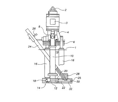
Fig. 1 is a side elevation view, partially in cross
section, of a molten metal gas injection pump of the
present invention;
Fig. 2 is a top view of the pump of Fig. 1;
Fig. 3 is a detailed view of a section of the base
taken along line 3-3 of Fig. 2, particularly showing the
outlet passage including the nozzle;
Fig. 4 is a side elevation view of a nozzle creating
inserts and
Fig. 5 is a cross-sectional view of Fig. 4, taken
along lines 5-5;
Fig. 6 is a graphical representation of chlorine gas
injection rates demonstrating the effectiveness of the
present inventive design relative to gas injection pumps
without the nozzle;
Fig. 7 is a perspective view of one impeller type
used in testing of the present inventive design; and
CA 02262108 1999-O1-26
WO 98/04372 PCT/US97/13190
- 6 -
Fig. 8 is a graphical representation of chlorine gas
injection rate versus motor speed.
Detailed Description of the Invention
While the invention will be described in connection
with the preferred embodiment, it is to be understood that it is
not intended to limit the invention to that embodiment. On the
contrary, it is intended to cover all alternatives, modifications
and equivalents as may be included within the spirit and scope
of the invention defined by the appended claims.
Referring now to FIGURE 1, a typical gas injection pump
1 is depicted. Particularly, the pump 1 includes a hanger
assembly 2 used for lifting and positioning of the pump as
necessary within a furnace (not shown). A motor 3 is supported
by a motor mount 4, itself supported by a support plate 6. The
motor 3 is connected via a coupling assembly 8 to a rotatable
shaft 10 secured to an impeller 12.
A base assembly 14 rests on the floor of a refractory
furnace and forms a foundation for the support plate 6 and motor
mount 4 by a plurality of posts 16. The impeller 12 is rotatable
within a pumping chamber 18 and it's rotation draws molten metal
19 into the pumping chamber i8 through an inlet 20 and discharges
the molten metal through an outlet passage 22.
A reactive gas is provided to a gas injection tube 24
supported by a clamping mechanism 26 attached to the support
plate 6. The submerged end of the gas injection tube 24 is
connected via a tube plug 2B to the outlet passage 22. Adjacent
the discharge opening 30 of the outlet passage 22 is a convergent
CA 02262108 1999-O1-26
WO 98/04372 PCT/US97/13190
nozzle 25. Particularly, the outlet "necks down" to form an area
of restriction 32 (a "zone of convergence") injection paint.
This restriction is more particularly shown in Figure 3 where a
cross section of the base is shown.
' 5 Although the depicted design places the nozzle 25
adjacent the opening 30, the inventive pump is equally functional
when the nozzle is positioned further "upstream" in the outlet
passage, i.e., closer to the pumping chamber, provided the gas
injection point remains upstream. In such a design, the nozzle
becomes a convergent-divergent type within the outlet passage.
Further, although the base assembly 14 is shown as a
substantially one-piece unit, it is expected that at least the
outlet passage section may be a separate component/extension
secured to the main body.
Surprisingly, it has found that the present inventive
design results in significant increase in maximum chlorine
reacted and therefore, the rate at which magnesium can be removed
from the molten aluminum. Attached as Figure 6 is a graph
showing the quantity of chlorine which is solubilized into the
molten aluminum at a variety of speeds of operation of a
Metaullics System Co., L.P. L35 gas injection pump. A similar
comparison is provided by Figure 8 wherein chlorine injection
relative to pump speed (RPM) is shown. As is clear from the
graphs, the inventive discharge nozzle allows significantly
larger quantities of chlorine to be chemically absorbed by the
molten aluminum at all levels of tested pump speeds.
Without being bound by theory, it is believed that the
nozzle increases the velocity of the aluminum after the gas has
CA 02262108 2002-06-17
8
been injected. The mixture of the gas and aluminum then
is discharged into the charge well in a high speed jet
resulting in high power turbulence and therefore better
degassing and demagging. In the convergent-divergent
design, the diverting section allows for a controlled
reaction zone before expulsion into the bath while
maintaining an intimate gas metal mixing zone, i.e. the
zone convergence. This embodiment is exemplified in Fig.
3 by the line A-A, where the nozzle could be positioned
to form a convergent-divergent nozzle within the outlet
passage and allows for the gas injection to occur at the
location of metal divergence, i.e., just downstream of
the nozzle yet within the outlet passage.
Hereinbelow is Table l, depicting test results of
various gas injection pumps operating with different
impellers of the types described in United States Patent
5,470,201 issued November 28, 1995 (impeller 1), and
United States Patent No. 5,785,494 (impeller 2), and in
Fig. 7 (impeller 3). As a review of Table 1 will show, a
gas injection pump fitted with the inventive nozzle
design consistently results in an unexpected rise in the
quantity of chlorine which can be solubilized by the
molten aluminum.
TABLE 1
IMPELLER WITH NOZZLE
1
RPM AMPS CI~2 MG% TEMP
700 14 340 0.041345 Light puffs
650 16 290 0.041344 Light puffs
600 15 195 0.041344 Clear
550 14.5 180 0.041344 Clear
500 13.5 175 0.041344 Very light puffs
450 12.5 130 0.041344 Clear
400 11.5 90 0.041344 Clear
CA 02262108 1999-O1-26
WO 98104372 PCT/L1S97113190
_ g _
IMPELLER 1 WITHOUT NOZZLE
RPM AMPS CL2 MG% TEMP
700 20.5 200 0.055 1372 Maximum
650 18 165 0.055 1372 Maximum
IMPELLER 2 WITH NOZZLE
RPM AMPS CL2 MG% TEMP
700 19 380 0.10 1470 Not Maximum
650 17.5 355 0.10 1470 Maximum
600 16 300 0.10 1470 Maximum
550 15 135 0.10 1470 Maximum
500 14 95 0.10 1470 Maximum
IMPELLER 2 WITHOUT NOZZLE
RPM AMPS CL2 MG% TEMP
700 22 180 0.10 1485 Maximum
650 19 145 0.10 1485 Maximum
600 17 95 0.10 1485 Maximum
550 16 85 0.10 1485 Maximum
IMPELL ER 3 WITH NOZZLE
RPM AMPS CL2 MG% TEMP
700 23 250 .03 1460 Maximum
650 22 210 .03 1460 Maximum
600 20 155 .03 1460 Maximum
550 19 120 .03 1460 Maximum
500 18 95 .07 1460 Maximum
CA 02262108 1999-O1-26
WO 98!04372 PCT/US97113190
- 10 -
IMPELLER 3 WITHOUT NOZZLE
RPM AMPS CIr2 MG o TEMP
700 26 210 .07 1460 Maximum
650 24 170 .07 1460 Maximum
600 22 150 .07 1460 Maximum
550 20 !I5 .07 1460 Maximum
500 18 95 .07 1460 Maximum
As stated above, reduction in magnesium levels is a
critical step in aluminum refining. Since the inventive molten
metal gas injection pump results in significant increase in
chlorine injection and hence a more rapid reduction in magnesium
levels, the present invention is highly advantageous.
Similarly, as those skilled in the art will understand,
the typical mechanism for increasing chlorine injection rates is
to increase the speed of pump operation. With the present
invention, aluminum refiners are able to run molten aluminum
pumps at slower speeds yet obtain higher rates of chlorine
reaction. Since pumps include dynamic pieces of equipment which
can experience failure, this less stressful operation will
provide significant advantages to the refiners.
In addition, it is noted that the prior art gas
injection pump design often requires very long discharge tubes
that clog with dross and other scrap. In contrast, the present
design requires a much shorter outlet nozzle which can be readily
cleaned when the pump is removed from the molten aluminum
environment.
Furthermore, the nozzle modification is easily
accomplished at a low cost. Particularly, as shown in Figure 3,
one option is to include a separate nozzle 25 (Figures 4 and 5),
cemented into a traditional discharge outlet. Alternatively, the
SUBSTITUTE SHEET (RULE 26)
CA 02262108 1999-O1-26
WO 98/04372 PCTIUS97I13190
- 11 -
discharge can be machined as a one-piece unit having a reduced
diameter downstream of the gas injection point.
Thus, it is apparent that there has been provided, in
accordance with the invention, a gas injection pump that fully
satisfies the objects, aims, and advantages set forth above.
While the invention has been described in conjunction with
specific embodiments thereof, it is evident that many
alternatives, modifications and variations will be apparent to
those skilled in the art in light of the foregoing description.
Accordingly, it is intended to embrace all such alternatives,
modifications, and variations as fall within the spirit and broad
scope of the appended claims.