Note: Descriptions are shown in the official language in which they were submitted.
-' ~ = CA 02262560 1999-02-05 0 40
~ JUN-29-98 11:51 AM GaLLEN,DYER,DOPPELT,ETqL. 407 841 2343 P.la 6
~ T H ,s aM E Fi,D t s PCT/US 9 7 / 1 4 _ 6
F: AIa,CZ ' IPEA/US29,
1998
IMPROVED 1DC I-IAVINC WIRE SLI_PPAGE CC),NI$,Q~
Back-eround of the Inyention
The present invention relates to insulation displacenient contact (TDC's), and
nicere
particularly to an improved IDC having means for controlling slippage of a
wire terminated
thercin when the wire is subjected to small movements.
IDC's have been around for a long tinie and are very popular. This popularity
is due
in part to their ease of use, economy, versatility, and effectiveness, For
many applications,
IDC designs havc reached a state of considerable refinement.
Onc area, however, which could stand improvernent has to du with making IDC
blades more robust for maintaining a durable and reliable connection to wires
that may be
subjected to srnall movements while in the installed or terminated pcisition
in the. IDC. Prior
art solutions have typically relied upon restraining means apart from the IDC,
rather than the
IDC itself, but this can involvc additional structurc which in turn catises
additional costs.
U.S. PatEnt No. 4,002,391 to Dutin et al., discloses an insulation
displacement contact
having a bridge and two pairs of upstanding, adjacent arnzs and a sniall
"boss" or swage on its
arnts, and positioncd equal distances along the longitudinal axis.
A need therefore remains for IDC bladcs and associated methods that are
inhererttly
resistant to wire slippage of a wire terminated therein.
Sunimlrv of the Invention
Briefly, the present invention nteets the above needs and purposes with a ncw
and
improved insulation displacement contact, and in particular such an insulation
displacentent
contact in which its wire-receiving slot has a unique detent provision. for
retaining a wirE:
thereitt after the wire has been pushed into the slot, In the prefened
embodiment, the detent is
a boss %vhich intrtides into the slot to form a narrower passage in the slot
at that location. The
boss is preferably formed by stamping followed by coining, altllough the
process which is
chosen Nvill depend upon the desired IDC diinensions, the thickness of the
metal plate from
which the IDC is fornled, and so forth, In this case, a bump is first fornied
by stamping, and
02262560 1999-02-05 =
= JUN-29-98 11:51 AM ALLEN,DYER,DOPPELT,ETAL. 407 841 2343 P.05
PCTlUS 9 7
lPEA/US 29 .iw"998
then enlnrged by punch coining to the desired dimension. (Punch coining refers
to coining by
striking with a dcfined punch geometry.)
In usc, the insul:ited wire is then pushed into this slot, causing the
insulltion thereon
to be displaced and contpleting an electrical connection to the Il?C, As the
wire is
progressively pushed farther into this slot, it is forced past the detent.
This results in a
. ~.;
CA 02262560 2006-02-15
26775-252
-2-
more stable and reliable termination for the wire since it
will now not easily escape from the slot if subsequently
subjected to small movements.
Preferably, when the IDC has multiple wire
terminating slots, the detents are staggered so that wires
which are being simultaneously terminated in the slots will
progressively encounter the detents, one at a time, to make
insertion and removal of the wires easier.
According to one aspect the invention provides an
insulation displacement contact comprising: a) a bridge, b)
a first pair of adjacent arms depending from said bridge and
defining therebetween a first conductive slot having a
vertical longitudinal axis that intersects the bridge and
configured for receiving an insulated wire, displacing the
insulation thereon, and completing an electrical connection
thereto, and c) a first detent formed in said first slot on
at least one of said first pair of arms for retaining a wire
therein after being pushed into said first slot past said
first detent, wherein said first detent is positioned a
greater vertical distance from said bridge than any other
detent in said first slot, d) a second pair of adjacent arms
depending from said bridge and defining therebetween a
second conductive slot having a vertical longitudinal axis
that intersects the bridge and configured for receiving an
insulated wire, displacing the insulation thereon, and
completing an electrical connection thereto, and e) a second
detent formed in said second slot on said second pair of
arms thereof for retaining a wire in said second slot after
being pushed into said second slot past said second detent,
wherein said second detent is positioned a greater vertical
distance from said bridge than any other detent in said
second slot and wherein said second detent in said second
slot is positioned a greater vertical distance from said
CA 02262560 2006-02-15
26775-252
-3-
bridge along the vertical longitudinal axis than the first
detent.
According to another aspect the invention provides
a method for receiving an insulated wire, displacing the
insulation thereon, and completing an electrical connection
thereto, comprising a) inserting a first wire into a first
conductive slot in an insulation displacement contact having
a bridge and a first pair of adjacent arms depending from
the bridge and defining therebetween the first conductive
slot, which extends along a vertical longitudinal axis that
intersects the bridge, the first slot being configured for
displacing the insulation and completing the electrical
connection, b) pushing the first wire into the first slot
past a first detent depending in the first slot from at
least one of the first pair of adjacent arms for retaining
the first wire in the first slot after being pushed into
first slot past the first detent, wherein said first detent
is positioned a greater vertical distance from said bridge
than any other detent in said first slot; c) inserting a
second wire into a second conductive slot that extends along
a vertical longitudinal axis that intersects the bridge and
is formed by a second pair of adjacent arms depending from
the bridge, and d) pushing the second wire into the second
slot past a second detent formed in the second slot on at
least one of the second pair of adjacent arms thereof for
retaining the second wire in the second slot after being
pushed into the second slot past the second detent, wherein
said second detent is positioned a greater vertical distance
from said bridge than any other detent in said second slot
and wherein said second detent in the second slot being
positioned a greater vertical distance from the bridge along
the longitudinal axis than the vertical distance of the
first detent.
CA 02262560 2006-02-15
216775-252
-4-
These and other objects and advantages of the
invention will be apparent from the following description,
the accompanying drawings, and the appended claims.
Brief Description of the Drawings
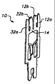
Fig. 1 is an isometric illustration of an
insulation displacement contact having wire slippage and
movement control according to the invention;
Fig. 2 is an elevation of the Fig. 1 contact;
Fig. 3 is an enlarged fragment of the displacement
contact of Figs. 1 and 2; and
Fig. 4 is a cross-sectional view taken on line 4-4
in Fig. 3.
Description of the Preferred Embodiments
With reference to the drawings, the new and
improved insulation displacement contact having wire
slippage and movement control, and the method therefor
according to the present invention, will now be described.
Fig. 1 is an isometric illustration of such an insulation
displacement contact 10. As shown therein, contact 10
includes a pair of arms 12a and 12b depending from a
bridge 14. Arms 12 thus define a conductive slot 15
configured for receiving an insulated wire (not shown),
displacing the wire's insulation, and completing an
electrical connection thereto. In the preferred embodiment,
the IDC 10 is formed by stamping from a sheet of copper
alloy metal.
In slot 15 and depending from either arm (in this
case, arm 12b), is a detent 20 for retaining a wire in
slot 15 after the wire is pushed into the slot past the
CA 02262560 2006-02-15
26775-252
-5-
detent 20. In the preferred embodiment, detent 20 is a boss
which intrudes into the slot to form a narrower passage 23 in
the vicinity of the boss 20. The boss can be formed by any
conventional process, depending upon the dimensions and
preferred characteristics. These include stamping, coining,
punch coining, or any combination thereof.
The particular IDC configuration illustrated
herein is an improvement on the IDC shown in United States
Patent No. 5,423,694, issued June 13, 1995, and assigned to
the assignee of the present invention. That '694 patent
shows an IDC having multiple slots for simultaneously
terminating several wires, preferably one per slot.
Accordingly, the present invention includes a second pair of
arms 32a and b also depending from bridge 14 to define a
slot 35 similar to slot 15. Slot 35 includes a detent 40
similar to detent 20, except that detent 40 is closer to
bridge 14 than detent 20. This staggers the detents to
reduce insertion and removal forces, particularly when used
in a terminal block such as shown in the '694 patent.
Near the bridge, 14 at the base of the arms 12
and 32, will be seen respective larger open areas 42 and 43.
These are beneath the slots 15 and 35, and are not part of
the active IDC slot area. Rather, they are for the purpose
of narrowing the bases of the arms 12 and 32 to make them
more resilient so that the IDC's can better accommodate
multiple wire gauges, as desired. When used with a terminal
block such as shown in the '694 patent, the block prevents
the wires from falling through to open areas 42 and 43, and
instead retains the wires in the slots below the detents 20
and 40.
As may be seen, therefore, the present invention
provides numerous advantages. Principally, it provides
CA 02262560 2006-02-15
26775-252
-6-
added security for keeping a terminated wire in the slot
when the wire is subjected to small vibrations and/or
movements. For example, when used in a terminal block such
as shown in the '694 patent, it is intended that the block
may be manipulated from time to time to, for example, add
additional wires thereto. At such time, previously
installed wires may be subjected to movement during this
installation process. Preferably, these wires would remain
terminated in their IDC slots. With the present invention,
this is much more reliably assured, since minor wire
movement will now not generate sufficient force to move the
wire back past the detent where it might then exit from the
slot. Another advantage of the invention results from the
staggered spacing of the detents within their slots, so that
the wires progressively encounter the detents, thus reducing
insertion and removal force. The invention thus provides a
straightforward, economical, robust, and highly effective
solution for assuring that a wire which is terminated in the
IDC will remain in the IDC until a definite decision is made
to remove it.
Of course, various modifications to the present
invention will occur to those skilled in the art upon
reading the present disclosure, and such are intended to be
included in the scope of the claims as appropriate to the
language and intent thereof.
Therefore, while the methods and forms of
apparatus herein described constitute preferred embodiments
of this invention, it is to be understood that the invention
is not limited to these precise methods and forms of
apparatus, and that changes may be made therein without
departing from the scope of the invention.