Note: Descriptions are shown in the official language in which they were submitted.
CA 02262865 1999-O1-28
WO 98105240 PCTlUS97112855
-1-
A TOOTHBRUSH
Field of the Invention
The present invention relates to a bristle arrangement for a toothbrush, more
particularly to
a toothbrush whose head has tufts arranged in distinct groups separated by
gaps which
extend from one side of the brush head to the other. The placement and
orientation of tufts
is such that the groups can operate substantially without interference from
neighbouring
groups of tufts, yet a high overall density of tufts on the toothbrush head is
still maintained.
Background of the Invention
Effective brushing of teeth requires both high bristle contact with all tooth
surfaces and
penetration of bristles into interdental gaps and other crevices. Typical
toothbrushes, with
uniform tuft spacing across the brush head, achieve high bristle contact but
interdental
penetration is limited by interference between neighbouring tufts i.e. the
whole set of
bristles tends to behave as one solid array.
Various arrangements of bristles on the toothbrush head which aim to improve
the quality
of brushing have been described.
WO 91/19437, for example, describes a toothbrush with a three-dimensional
bristle profile
for improved interproximal cleaning. EP-A-449,653 and EP-A-449,655 disclose
brushes
having tufts which are set at an angle to the toothbrush head and to each
other to clean the
gingival marginal area and the interproximal spaces. It is also said that the
tufts are unable
to support one another structurally, allowing individual tufts to penetrate
embrasures and
interproximal spaces without being inhibited by surrounding bristle tufts. WO
96/01578
recites a multi-level bristle tuft which has the object of stimulating gums
and imparting a
unique mouth sensation signalling effective cleaning. WO 96/15696 is directed
towards a
toothbrush with strips of a flexible, resilient material projecting from the
head which
enhance its tooth cleaning effect.
Alternative approaches to improving cleaning have included modifying the shape
or
behaviour of the brush head. WO 91/19438, for instance, discloses a toothbrush
with
weakened regions in the head which allow it to be deformed to suit the
particular size and
shape of the user's dental arches. There are rows of bristles missing at the
weakened
regions. WO 96/02165 and other documents referenced therein describe brushes
with
flexible heads which can adapt or be adapted to the user's teeth whilst
brushing.
CA 02262865 1999-O1-28
WO 98105240 PCTIUS97I12855 -
-2-
WO 94/09677 describes yet another variation wherein two general directional
orientations
of rectangular bristles are used on the same brush head in order to provide
improved
cleaning performance. The aforesaid document reviews earlier art describing
the use of
rectangular bristles to achieve different brushing characteristics for
different motions of the
brush.
Separately from all of this, the manner of using a toothbrush has received
much attention
from dental professionals over the years. Preferred methods for brushing
teeth, such as the
Bass and Rolling techniques are described in 'Primary Preventative Dentistry'
by N.O.
Harrison and A.G. Christen, 4th Edn., published by Appleton & Lange.
Despite all the foregoing, and much other literature on toothbrushes, there
remains a need
for improved brush designs.
It is accordingly an object of this invention to provide a toothbrush allowing
independent
movement of bristle tufts whilst maintaining a high overall density of tufts.
It is a further object of this invention to provide a toothbrush which allows
independent
1 S movement of bristle tufts whilst achieving a preferred orientation of
bristles to teeth
surfaces whilst brushing.
It is yet a further object of this invention to provide a toothbrush whose
head is comfortable
within the mouth and which has a bristle arrangement that assists improved
cleaning.
Summary of the Invention
According to the present invention there is provided a toothbrush having a
handle and,
attached at one end thereof, a head, the head having a handle end, a free end,
and a bristle-
bearing face with a plurality of tufts extending therefrom, the tufts each
having a base and a
free end and comprising one or more bristles, wherein the tufts are arranged
in groups
which are separated from each other by a transverse gap, the distance between
the bases of
the tufts within a group being less than I .3 mm, the distance between the
bases of the tufts
between groups being in the range from 1.3 mm to 5 mm and wherein the distance
between
the free ends of the tufts between groups is at least 0.5 mm.
According to a second aspect of the present invention there is provided a
toothbrush having
a handle and, attached at one end thereof, a resiliently flexible head, the
head having a
handle end, a free end, and a bristle-bearing face with a plurality of tufts
extending
therefrom, the tufts each having a base and a free end and comprising one or
more bristles,
wherein the tufts are arranged in groups which are separated from each other
by a
transverse gap, the distance between the bases~of the tufts within a group
being less than
1.3 mm and the distance between the bases of the tufts between groups being in
the range
3 5 from 1.3 mm to 5 mm.
CA 02262865 1999-O1-28
WO 98/05240 PCT/US97/12855
-3-
The arrangements allows for independent movement of bristle tufts yet maintain
a high
density of tufts on the brush head.
Detailed Description of the Invention
The toothbrush of this invention can be a single piece toothbrush, such as in
a conventional
manual design or it can have, for example, a replaceable head, such as in an
electrical
toothbrush, or the head can be fixed but have exchangeable bristle-bearing
inserts. The
toothbrush has a handle and, attached to one end thereof, a head. The design
of the handle
is not critical to the invention, it will generally be of conventional
elongate shape.
Preferably it will be ergonomically designed, building in such features as
elastomeric
inserts to improve the user's grip, and thumb or index finger rests to improve
handling. In
a prefer ed embodiment the handle has a neck portion which is arched
sufficiently that the
free working ends of the bristles, as described hereinafter, lie in
substantially the same
plane as the handle.
The toothbrush head has a bristle-bearing face with a plurality of tufts
extending therefrom,
a free end which has a tip, and a handle end. The head fwrher has two opposed
sides
which extend from the free end of the head to the handle end. The handle end
can be
continuous with an elongated handle as in a single piece toothbrush or it can
be adapted to
connect to a separate handle. In any case the long axis of the handle defines
a longitudinal
axis of the head, with the free end and handle end being at opposite ends of
the longitudinal
axis. The head also has a transverse axis lying orthogonal to the longitudinal
axis and
generally parallel to the bristle-bearing face. References to transverse or
longitudinal
herein refer to directions which are respectively parallel to these transverse
and longi-
tudinal axes, unless indicated otherwise. Suitably, the head itself is also
elongated, with its
elongated axis also being a longitudinal axis. The toothbrush head can also
comprise an
exchangeable insert which fits into a supporting frame, such as described in
EP-A-704,179.
In this latter case, by 'head' is meant the combination of the frame and
insert as would be
assembled for use in brushing one's teeth.
By 'tuft', herein, is meant a set of one or more bristles fastened to the
brush at a common
point. Bristles for use herein can be made of any of the materials well known
in the art.
Suitable bristle materials herein include polyester and nylon, such as Dupont
Tynex~ 612
and Stylon~ 612 from STP. The bristles are preferably of circular cross-
section but can
also be of other cross-sections including, but not limited to, rectangular,
hexagonal and
trilocular. Furthermore, the diameter and length of the bristles can vary
within the usual
dimensions known by a person skilled in the art. In preferred embodiments the
bristles are
of circular cross-section with a diameter of from 0.1 to 0.25 mrrl and length
of from 7 to 15
mm, preferably 9 to 12 mm, with each tuft comprising from about 10 to about 50
bristles.
CA 02262865 1999-O1-28
WO 98/05240 PCT/LJS97112855
-4-
In such embodiments, each tuft is generally circular with a diameter of from
about 1 to
about 2 mm. Cutting and end-rounding of the bristles can be done using any of
the
methods commonly known in the art. As used herein, the term 'bristle' also
includes other
flexible strips of cleaning material such as those described in WO 96/15696,
referenced
above. In such cases a tuft will suitably comprise just one bristle. Fastening
of the bristle
tufts to the brush head can be done using any of the methods known in the art,
such as
fusion, stapling and injection moulding. Preferred processes herein are
stapling and fusion.
Each tuft has a base and a free end, the free ends of the tufts forming the
working surface
which is used to clean the teeth. As used herein, the 'base' of the tuft is
that part of the tuft
at which it meets the face of the brush head. It will be understood that a
portion of the tuft
extends below the base into the brush head, for the purpose of anchoring the
tuft into the
head. It is preferred for the head to comprise pre-moulded tuft holes for the
purpose of
accommodating that portion of the tuft in this way. The tuft holes can be of
any section
including square and rectangular but are preferably circular. Their depth and
diameter will
I S be chosen by the man ordinarily skilled in the art to suit the tufts to be
inserted therein.
Bristles inserted into a common tuft hole are considered to be fastened at a
common point
and to be part of the same tuft.
The head is of length L, the length being measured between the tip of the free
end and a
line drawn perpendicular to the long axis of the head just touching the tuft
or row of tufts
nearest the handle at the points of their base closest to the handle.
Generally L will be in
the range from about 15 to about 35 mm, preferably from about 20 to about 30
mm.
The tufts are arranged in a plurality of groups, N, with each group being
separated from
adjacent groups) by a transverse gap; there being N-1 gaps. N is at least two,
preferably
from 3 to 5, more preferably 4. Each group comprises one or more tufts,
preferably from
about 5 to about 20 tufts, more preferably from about 7 to about 12 tufts. The
total number
of tufts is suitably from about 25 to about 50, preferably from about 30 to
about 40, more
preferably about 35. By 'transverse gap' is meant a region on the bristle-
bearing face which
is devoid of tufts and extends from one side of the head to the other, such
that each gap has
two ends, one located at each side of the head. The transverse gaps can be
linear or non-
linear, being determined by the pattern of tufts on the bristle-bearing face.
A straight line
drawn between the two ends of a gap is preferably parallel to the transverse
axis of the
head but can also be obliquely oriented to the transverse axis.
Within each group, the distance between the bases of neighbouring tufts is
less than 1.3
mm, preferably from 0.6 to 1.2 mm, more preferably from 0.8 to 1.1 mm.
Distances
between the bases of the tufts, as referred to herein are measured from tuft
edge to tuft edge
along a straight line drawn between tuft centres along the bristle-bearing
face. Distances
between the free ends of the tufts, as referred to herein, are measured from
tuft edge to tuft
CA 02262865 1999-O1-28
WO 98/05240 PCTIUS97/12855
-5-
edge along a straight line drawn between tuft centres, parallel to the bristle-
bearing surface,
from the free end of the shorter tuft. Unless specifically defined otherwise,
distances
between tufts refer to distances between neighbouring tufts. By 'neighbouring
tuft' is
meant the closest nearby tuft.
The distance between the bases of neighbouring tufts in adjacent groups, that
is, measured
across the gap between groups, is in the range from about 1.3 mm to about 5
mm,
preferably from about 1.5 to about 3.5 mm, more preferably from about 1.7 to
about 3 mm.
There can be some variation across individual pairs of tufts but all pairs,
where the
members of each pair are in different groups will be at least 1.3 mm part at
their bases.
By having a relatively large distance between tufts in adjacent groups, the
groups of tufts
are able to operate independently of each other. That is, tufts from one group
do not
substantially obstruct tufts from an adjacent group. This allows tufts on the
margins of the
groups, in particular, to penetrate better into the interproximal gaps and
other crevices.
Nevertheless, a relatively high, overall density of tufts on the brush head is
maintained by
the relatively small distance between tufts within groups. This, in
particular, provides for
good bristle coverage on individual tooth surfaces.
To maximise the benefits of the invention it is necessary that, not only are
the tufts spaced
apart at the base, but also that they do not interfere at their free ends in a
way which would
impair their individual movement when the brush is use. For a conventional
rigid brush
head the distances between free ends of the tufts between groups should be at
least 0.5 mm,
preferably at least 1 mm, more preferably at least 1.7 mm. This condition is
automatically
satisfied when the tufts are parallel to each other and the bristles within a
tuft do not
diverge towards their free ends.
Tufts can be generally perpendicular to the bristle-bearing face of the
toothbrush head, or
inclined at a more pronounced angle. By 'generally perpendicular' is meant
that the central
axis of the tuft is oriented at an angle of no more than 10° to a
perpendicular from the
centre of the bristle-bearing face. Preferably at least 70%, more preferably
at least 80% of
the tufts are generally perpendicular to the bristle-bearing face of the
toothbrush head. In
especially preferred embodiments, ail of the tufts are generally perpendicular
to the bristle-
bearing face of the toothbrush head such that they are all essentially
parallel to each other.
Tufts which are generally perpendicular to the bristle-bearing face give
better cleaning
because they are then generally applied more or less perpendicular to teeth
surfaces. They
are also less susceptible to 'splay', the tendency of bristle tufts to become
flattened on
repeated usage. Splayed tufts have an unsightly appearance and impair the
cleaning effect
of the brush. Some tufts, however, can be inclined at an angle of more than
10° to the
bristle-bearing face. As an example, it may be desirable to have some tufts in
the outer
CA 02262865 1999-O1-28
WO 98105240 PCT/US97/I2855 -
-6-
longitudinal rows inclined to the side of the brush head for more gentle
cleaning of the
gingival margins. Preferably tufts are not inclined towards each other,
especially across the
gap between groups, since this detracts from the benefit of the present
invention.
On a resiliently flexible brush head, as described hereinafter, the need to
have the distances
between free ends of the tufts between groups be at least 0.5 mm can be
relaxed. This is
because during use, when pressure is applied to the brush, it tends to adopt a
more convex
configuration and the tuft free ends move apart from each other. Nevertheless,
it is still
preferred that the tuft free ends are at least 0.5 mm, preferably at least 1
mm, more
preferably at least 1.5 mm apart.
The overall density of tufts on the brush head is a function of the size of
the head and the
number of tuft groups as well as the size of the gap between groups. In
preferred
embodiments, the average distance (G) between neighbouring tufts in adjacent
groups is in
the range from about 0.15 * L / (N-1) to about 0.3 * L / (N-1). That is, when
there are
fewer groups, and hence fewer gaps between groups, the gaps can be larger,
though as gaps
are increased above 5 mm they do not provide any significant improvement in
individual
movement of groups of tufts and they are wasteful of space. The average
distance between
neighbouring tufts in adjacent groups is determined by taking the numerical
average of all
distances between pairs of neighbouring tufts, where one member of each pair
is located on
each side of the gap between groups.
Both the overall bristle tuft density and the freedom of individual tufts to
operate
independently of each other can also be influenced by the shape of the tuft
groups and the
disposition of tufts within the groups. Although rectangular groups of
bristles can be used,
with bristle tufts arranged in conventional straight rows, better results are
achieved if tufts
within a group are at least partially offset from each other along the
transverse axis. By 'at
least partially offset' is meant that, for any particular tuft, there is no
other tuft within a
distance of 1.3 mm, preferably I.5 mm, measured along a line parallel to the
transverse
axis, for at least 50% of the width of the tuft measured along the
longitudinal axis.
Especially, the distance to the next tuft is greater than 1.3 mm, preferably
greater than 1.5
mm, for at least 70%, more preferably 100% of the width of the tuft. In
preferred
embodiments at least 50%, more preferably at least 70% of the total number of
tufts are at
least partially offset for either of the two directions along the transverse
axis. In this way,
when brushing using the recommended Bass technique, in which the brush is
placed along
the teeth and moved up and down, tufts can more easily move past each other,
giving less
resistance to up and down movement than to longitudinal movement of the brush.
One
way of practising such offset dispositions is to have groups of tufts in the
shape of a
parallelogram, wherein the gaps between the groups are generally straight but
obliquely
oriented to the long and transverse axes of the brush head. A preferred
configuration is to
CA 02262865 1999-O1-28
WO 98/05240 PCT/US97112855 -
_7_
have one or more of the groups of tufts in a crescent or chevron-shaped array.
By 'crescent'
and 'chevron-shaped' is meant an array which is symmetric about the long axis
but with at
least two longitudinal rows of tufts within the array longitudinally displaced
from their
neighbours by a distance which is at least 20% of the average width of the
tufts so that the
whole group generally has the appearance of an arc or a'V' with an apex lying
on or close
to the central longitudinal axis. By making the groups to be a set of
interlocking shapes, in
which the gaps between groups are approximately parallel to each other, the
overall tuft
density is also maintained. In a preferred embodiment this is achieved by
having at least
N-1 of the groups of tufts in a crescent shaped array. One end group,
preferably the one
nearest the handle end, need not be so formed. It can, for example, be oval,
diamond
shaped or circular. A further advantage of crescent or chevron-shaped groups
of tufts is
that they more efficiently utilise the space on brush head with a pointed or
rounded free
end. For this reason it is especially preferred to have the apex of the
crescent or chevron
directed towards the free end of the head.
The working surface formed by the free ends of the tufts can be of any
suitable shape, such
as flat, concave or rippled. Preferably it is cut to a wave profile as
described in WO
91/19437. More preferably, some of the outer rows of tufts will have a raised
profile as
described in WO 96/07343.
The toothbrush head of the present invention, is preferably resiliently
flexible, as described
for example in WO 96/02165. By 'resiliently flexible' is meant herein that
when a 3
Newton force is applied to the free end of the head, the handle end being held
fixed
immediately behind the last transverse row of bristles, the free end will
deflect through an
angle (the flex angle) of at least 2°, preferably at least 5°,
more preferably at least 10°, and
that further, when the 3 Newton force is removed, the free end of the head
will return to its
original position without the application of external force. The flex angle is
less 40°,
preferably less than 30°, more preferably less than 20°. This
has been found to give an
acceptable degree of flexibility for users without exposing the hinges and
elastomer-
segment bonds to undue stress. It is also preferred that the toothbrush head
has a concave
bristle-bearing face in its unstressed state. A resiliently flexible brush
head can better adapt
to different profiles of teeth and its assists the penetration of individual
tufts into
interproximal gaps and other crevices. It is also preferred that the bristle-
bearing face of
the toothbrush head is concave along the longitudinal axis in its unstressed
state. The
radius of curvature can vary along the length of the head. The radius of
curvature is
preferably from 10 to 500 mm, more preferably from 15 to 250 mm, especially
from 25 to
150 mm.
A further advantage of having relatively large gaps between groups is that the
gaps can
then accommodate transverse grooves on the bristle-bearing face for the
purpose of making
CA 02262865 2002-05-13
8
the head flexible, as described in WO 96102165. The grooves allow the head to
flex or
bend. The grooves can be linear or non-linear, but will preferably follow the
shape of the
BaP.
In preferred embodiments herein, the toothbrush head comprises a transverse
grooves in
each of the gaps between groups of tufts so that the head can bend along the
long axis.
This allows the toothbrush head to flex so that it can acquire a convex
profile along the
long axis when pressed against the teeth. This makes it particularly suitable
for brushing
the lingual or inside surfaces of the teeth. Preferably there are matching
grooves on the
reverse face of the brush and the grooves are preferably filled with an
elastomer as
described in WO 96/02165. A preferred manner of constructing a flexible brush
head is in
accordance with our co-pending patent application GB 9601013, briefly
summarised below
for the purpose of better describing the best mode of practice of a brush
according to the
present invention.
The brush head has a pair of opposing faces, one of the pair being a bristle-
bearing face
with bristles attached to and extending from the face. The head comprises two
or more
flexibly connected segments, with grooves between the segments, to allow the
head to flex
under the action of brushing and accommodate itself to, for example, the
differing profiles
of individual users' teeth. The head further includes elastomer contained
within the
grooves on at least one face. The elastomer can improve the resilience of the
head by
acting like a spring, so that when a force applied to bend the head is
removed, the head
returns within a short period of time to its original configuration. The
grooves define
hinges between the segments. The hinges are preferably located between the
faces,
preferably at a distance of at least about 10% of the depth of the head from
each of the
faces, rather than being co-extensive with either of the faces. The elastomer
can also act to
limit the degree of bending so that when high levels of force are applied the
head flex is
limited, largely reducing the incidence of excess strain on the hinges and
thereby
improving the durability of the product.
The head and handle are generally made of relatively non-compressible
materials,
preferably with a modulus of elasticity of at least about 500 MPa, more
preferably at least
about I 000 MPa, which are conventional in the manufacture ~ of toothbrushes,
especially
plastics materials. Suitable plastics materials include, for example,
polyamides and poly
propylenes. PolypropylTMe is preferred. Suitable polypropylenes include the
material
'Polypropylene PM 1600' (marketed by Shell), having a modulus of elasticity
(ISO 178) of
TM
1500 MPa and Apryl 3400 MA 1 from Elf Atochem. Preferably, a foaming agent
such as
TM
Hydrocerol HP20DP from Boehringer-Mannheim is mixed with the polypropylene at
a
level of from about 1 % to about 3%, preferably from about 1.5% to about 2.5%,
by weight
of the polypropylene. The foaming agent assists the flow of the polypropylene
during
CA 02262865 1999-O1-28
WO 98105240 PCTIUS97/12855
-9-
moulding and, in particular, helps to ensure uniform formation of the hinges.
The handle
itself is generally rigid and may be of a shape which is conventional in the
manufacture of
toothbrushes. Optionally, the handle can comprise a neck portion which is more
flexible
than the rest of the handle, as known in the art, provided that it is
sufficiently rigid that, in
use, when force is applied to the head, particularly when brushing the teeth,
the head still
flexes in the manner and to the extent described below.
The brush head includes grooves on the bristle-bearing face and the opposing
face, the
grooves being the spaces between the segments. The grooves allow the head to
flex or
bend. The grooves can be oriented transverse or parallel to the longitudinal
axis of the
handle and can be linear or non-linear, such as curved or zigzag. Non-linear
grooves help
to offset compression stress in the elastomeric material filling the grooves
as the head
bends. The term 'transverse grooves' can also encompass grooves whose main
axis, as
defined by the straight line joining the start and endpoints of the grooves is
offset from the
transverse axis of the head by an angle of up to and including 45°.
Similarly, the term
'longitudinal grooves' can also encompass grooves whose main axis, is offset
from the
longitudinal axis of the head by an angle of up to 45°.
In preferred embodiments the brush head comprises one or more transverse
grooves on
each of the opposed faces so that the head can bend along the longitudinal
axis. This
allows the brush head to flex so that it acquires a convex profile along the
longitudinal axis
when pressed against the teeth. This makes it particularly suitable for
brushing the lingual
or inside surfaces of the teeth.
The brush head can also comprise one or more longitudinal grooves.
Longitudinal grooves
can allow, for example, the outer longitudinal rows of bristles to flex away
from the inner
ones.
In especially preferred embodiments the brush head comprises both transverse
grooves on
each of the opposed faces so that the head can bend along the longitudinal
axis and at least
one longitudinal groove which connects the transverse grooves to permit the
elastomer to
flow from one groove to the other during the moulding process. In a single-
piece brush
with a co-moulded handle, this longitudinal groove can extend along the handle
so that the
same elastomer injection point in the mould that is customarily used for
supplying
elastomer to form handle grips can also be used to inject the elastomer for
the grooves of
the head. The longitudinal groove preferably runs along the back of the head,
that is, on
the face opposed to the bristle-bearing face, so that it does not interfere
with tufting.
Grooves on one of the two opposing faces can be directly opposed to grooves on
the other
face or partially or wholly offset. Preferably, the grooves are directly
opposed or only
partially offset.
CA 02262865 1999-O1-28
WO 98/05240 PCT/US97/12855 _
-10-
The grooves, which separate the segments of the head, also define hinges,
which are
thinned regions of the head at the base of the grooves.
The grooves can be of variable width and depth and the distances between
grooves can also
be varied. In this manner the flexibility of the head along the length and /
or across the
breadth of the head can be modified. Preferably only transverse grooves are
varied in this
way. Changing the depth of the grooves controls the location and thickness of
the hinges
which connect the segments. For a toothbrush head of between about 4 to about
6 mm
thickness, typically about 5 mm, suitable groove depths are in the range from
about 1.4 to
about 3 mm, preferably from about 1.5 to about 2.8 mm. Suitable hinge
thicknesses are in
the range from about 0.4 to about 2.0 mm, preferably from about 0.5 to about
1.5 mm.
Where transverse grooves are used then, desirably, the hinges which are or
will be nearer to
the handle are less flexible than those which are or will be more remote from
it. In this
way more uniform bending of the head can be achieved. The variation in
flexibility can be
achieved by varying the hinge thicknesses. In a preferred embodiment the hinge
nearest
the handle is up to about 3 times, preferably up to about 2 times as thick as
the hinge most
remote from the handle. An exemplary set of hinge thicknesses for a toothbrush
with 3
transverse grooves are respectively about 1.1, 0.6 and 0.6 mm reading from the
handle end.
If identical hinges are used along the brush head then there is a tendency for
flexing of the
head to occur predominantly at the hinge nearest the handle. The depth of
grooves on the
bristle bearing face can be different to those on the opposing face.
Preferably the grooves
on the bristle-bearing face are less deep than those on the opposing face. In
embodiments
where there is elastomer in the grooves on both faces, this allows more
elastomer to be put
under compression than under tension. The elastomer to segment bonds are
stronger under
compression than under tension.
Increasing the width of the grooves increase the gap between the segments and
therefore
the length of the hinges, which increases their flexibility. However, since it
is preferred to
insert bristles into the segments rather than into the elastomer, increased
groove length also
leaves less space for the bristles, within a given head size. Suitable groove
widths are in
the range from about 0.3 to about 3.0 mm, preferably from about 1.2 to about
2.0 mm. The
grooves are preferably tapered slightly inwards towards the bottom of the
groove, suitably
converging at an angle of from about 3 to about 10°, to facilitate
moulding. As the brush is
flexed the width of the groove changes, more rapidly at the top of the groove
than at the
bottom of the groove, the relative change being a function of the groove width
and depth.
Since this change in groove width results in compression or tension of
elastomer contained
within the groove, it can be seen that, for a given elastomer, the groove
geometry can be
used to control the head flexibility.
CA 02262865 1999-O1-28
WO 98105240 PCT/US97I12855 _
-I1-
The hinges can be the full length of the grooves or, preferably, there can be
one or more
gaps in or to the side of the hinges the grooves in these regions being the
full depth of the
head. This has the advantage of permitting a single injection point for the
elastomer when
moulding the head. The gap allows elastomer to flow from one face to the other
during the
moulding process. In a preferred embodiment, the hinges are discontinuous,
with two or
more hinges, preferably just two, connecting each segment to its neighbour or
to the
handle. In this embodiment there are gaps between the hinges and to each side.
In linear
grooves, the hinge widths are not generally critical, provided that they are
such that gaps
are still created, however, wide hinges can be subject to distortion if they
are used within a
I 0 non-linear groove. Suitable hinge widths are in the range from about 0.5
to about 4.0 mm,
preferably from about 1.0 to about 3.0 mm.
It is preferred that each hinge is located between the two faces and at a
distance of at least
about 10%, preferably at least about 20%, more preferably at least about 30%
of the depth
of the head from each of the faces. The distance of the hinge from the face is
measured by
1 S the perpendicular line drawn from the top of the face to the nearest
boundary surface of the
centre of the hinge. Locating the hinges away from the faces of the brush
means that they
are subject to less stretching or compression as the head is flexed and
improves their
durability. In a particularly preferred embodiment, the brush head has
transverse grooves
which are arranged in pairs such that one member of each pair is on each face
and directly
20 opposes the other member of the pair, with one or more hinges therebetween
connecting
the segments so that each hinge is located between the two faces and at a
distance of at
least about 10%, preferably at least about 20%, more preferably at least about
30% of the
depth of the head from each of the faces.
The grooves on at least one face of the brush contain elastomer. This can be
achieved by a
25 separate injection moulding step after the moulding of the segments of the
head has been
completed. Preferably, all of the elastomer is injected from a single
injection point.
However, there can be separate elastomer injection points in the mould to
supply the
elastomer for discrete elastomer elements in the head, for example one to
supply elastomer
to the bristle-bearing face and a further injection point to supply elastomer
to the opposing
30 face. Thus when the head is flexed in a direction orthogonal to the opposed
faces, the
elastomer is put either under tension or under compression. The elastomer has
the effect of
limiting the head flexibility thereby reducing the stretching or compression
of the hinges
and of limiting the stress at the bond between the elastomer and the head
segments. A
more durable head is thus obtained. Preferably, grooves on both the bristle-
bearing face
35 and the opposing face contain elastomer so that elastomer is put under
compression
whichever direction is chosen. The elastomer on the opposed face is of course
put under
CA 02262865 2002-05-13
-12-
tension but the tensile stress on the elastomer to segment bonds is limited
and is shared
with the hinge material.
Preferably all of the grooves are wholly filled with the elastomer, generally
by a separate
moulding process after the moulding of the head segments has been completed.
Complete
filling of the grooves has an advantage of, for example, avoiding
contamination of the
grooves by toothpaste deposits. The grooves can be partially filled though,
provided that
sufficient elastomer is used to give effective moderation of the flexibility
of the head.
Suitable elastomers include thermoplastic elastomers with a Shore hardness of
30 - 80 and
a modulus of elasticity of less than about 500 MPa, preferably less than about
300 MPa,
TM TM
such as Santoprene and Thermoflex. An exemplary elastomer is 'PTS Thermoflex
75'
(marketed by Plastic Technologie Service, Germany), having a modulus of
elasMicity (ISO
178) of 100 I~Pa and a hardness (ISO 8b8) of 80 Shore A. Elastomers PL12291,
PL12292,
and PL 12293 (marketed by Multibase, Saint Lawent Du Pont, France) are also
suitable for
use herein. In general, choosing the elastomer so that is based upon the same
chemical
class of polymers as material of the head segments assists in bonding the
elastomer to the
head segments. For example, when the head segments are made from
polypropylene, the
elastomer is preferably based upon polypropylene. The elastomers can
optionally be
mixed with a suitable plasticises or foaming agent to make them more
compressible. The
colour of the elastomer material can be the same as that of the head segments,
or it may be
different thereby achieving a distinctive striped or otherwise patterned
appearance.
The present invention will now be described by way of example only, with
reference to the
accompanying drawings in which:
Fig. 1 is a plan view of a first embodiment of the invention showing the
layout of the
tufts on the toothbrush head.
Fig. 2A is a plan view of another embodiment with elastomer filled transverse
grooves
placed within the gaps between groups of tufts.
Fig. 2B is a side view of the embodiment of Figwe 2A, elastomer in the groove
nearest the
handle is not shown in order to reveal the hinges.
Fig. 3 is a perspective view of a toothbrush head according to the invention.
Fig. 4 is a schematic plan view showing the measwement of offsets of tufts
along the
transverse axis.
Referring to Fig. l, a toothbrush head 1 has a rounded free end 2, having tip
3, handle end
4, and sides 5 extending from free end to handle end. A plurality of tufts 6
extend from the
CA 02262865 1999-O1-28
WO 98105240 PCT/US97/12855 _
-13-
bristle-bearing face 7. The tufts are arranged in four groups separated from
each other by
gaps 8. The three groups nearest the free end are each in the form of a
crescent shaped
array. The group nearest the handle end is generally in the shape of an oval
or diamond.
Within each group the tufts are relatively closely spaced, the distance T
between the bases
of neighbouring tufts varying from 0.6 to 1 mm. Neighbouring tufts in adjacent
rows are
offset from each other along the transverse axis so that their free ends can
more easily
move past each other when brushing via the Bass technique. The distance
between the
bases of neighbouring tufts in adjacent groups varies from 1.9 to 3 mm. The
length, L, of
the head is 29.6 mm.
Refernng to Figures 2A and 2B, the toothbrush head 1 has elastomer filled
grooves 9
which make the head 1 resiliently flexible. When a 3 Newton force is applied
to the tip of
the free end of the head, the handle end being held fixed immediately behind
the last
transverse row of bristles, the free end deflects through an angle of
15° and, when the 3
Newton force is removed, the free end of the head returns to its original
position without
the application of external force. The bristle-bearing face of the head is
concave along the
longitudinal axis in its unstressed state, having a radius of curvature of 75
mm. The
grooves 9 divide the head into segments 10. The segments are connected only by
pairs of
thin hinges 11. For the sake of clarity only the hinges in the groove nearest
the handle end
are shown, the others being obscured by elastomer. The tufts are arranged in
four groups
separated from each other by gaps 8. The three groups nearest the free end are
each in the
form of a crescent shaped array. The group nearest the handle end is generally
in the shape
of an oval or diamond. The tufts are all generally perpendicular to the
bristle bearing
surface, that is, the central axis of each tuft is oriented at an angle of no
more than 10° to a
perpendicular, shown by the line Z-Z in figure 2B, from the centre of the
bristle-bearing
face. This has the result that the distance (F) between the free ends of the
tufts is
essentially the same as the distance between the bases. Because the bristle-
bearing face of
the head is concave in its unstressed state, the tufts at each end of the
head, though parallel
to the central axis (Z-Z}, and to each other, are not perpendicular to the
bristle-bearing
surface at their point of attachment. According to a further aspect of the
invention it is
preferred to mould a curved brush head with tuft holes which are all axially
parallel to the
axis Z-Z. This has the benefit that during the moulding process, the pins
which are used to
create the tuft holes are more easily removed from the moulded brush body
without
distortion of the tuft holes.
Figure 3 shows an embodiment of the brush head, having a transverse axis (X-X)
and a
longitudinal axis (Y-Y), wherein thirty-five bristle tufts 6 are arranged in
four groups with
transverse gaps 8 between the groups. The tufts are arranged in four groups
separated from
each other by gaps 8. Each group is in the form of a crescent shaped array.
The tufts are
CA 02262865 1999-O1-28
WO 98105240 PCTIUS97I12855 -
- 14-
all perpendicular to the bristle-bearing face of the head and are
substantially of the same
length so that their free ends 12 form a flat working surface. Within each
group the tufts
are relatively closely spaced; the distance between the bases 13 of
neighbouring tufts varies
from 0.7 to 1 mm. The tufts are symmetrically disposed about the long axis Y-Y
of the
head. Whichever direction is chosen along the transverse axis, for thirty of
the tufts the
there is no tuft within 1.3 mm, measured along a line parallel to the
transverse axis for at
least 60% of the width of each tuft. 'For reasons of symmetry, the central two
tufts within
the rows containing four tufts lie on the same transverse axis. The tufts in
the row nearest
the free end 2 of the head are slightly offset from each other. The head
comprises
elastomer filled transverse grooves 9 which lie in the gaps between the
groups.
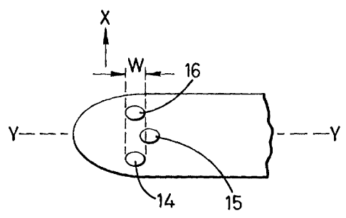
Figure 4 shows a part plan view of a head where, for reasons of clarity, only
three tufts, 14,
and 16, are shown. The transverse axis lies perpendicular to longitudinal axis
(Y-Y).
Tuft 14 has width W, measured along the longitudinal axis. Looking along the
transverse
axis in direction X, for 70% of the width W, the next tuft to tuft 14 is tuft
16, which is at
15 least 2 mm away for the full width W. However, for 30% of width W, the
transverse
projection of tuft 14 overlaps with tuft 1 S which is less than 1.3 mm away
along direction
X. The same analysis applies to tuft 15 in respect of tuft 16. For tuft 16,
since it is in an
outer row, there is no tuft in the direction X.