Note: Descriptions are shown in the official language in which they were submitted.
CA 02263008 1999-02-25
BIFURCATED STENT WITH IMPROVED SIDE HRAN~_'H APERTURE
AND METHOD OF MAKING SAME
Field of the Invention
The present invention relates to stems, and more
particularly to bifurcated stents and methods of making
bifurcated stems for insertion within a branching vessel.
Backcrround of the Invention
Stents are well known in the art. They are typically formed
of a cylindrical metal mesh which can expand when pressure is
internally applied. Alternatively, they can be formed of wire
wrapped into a cylindrical shape or sheets of material formed
into a cylindrical shape.
Stents are devices which are usually implanted within bodily
conduits including the vascular system to reinforce collapsing,
partially occluded, weakened, or abnormally dilated sections of
the blood vessel. Stents also have been successfully implanted
in other areas, e.g., the urinary tract or the bile duct to
reinforce such bodily conduits.
U.S.~Patent No. 4,994,071 (MacGregor) discloses an
expandable, bifurcating stmt having a main cylindrical lattice
formed from interconnected flexible wire. Two additional
cylindrical lattices, having smaller diameters than the main
lattice, are similarly constructed. The main lattice includes a
flexible wire interconnecting the main lattice to one of the
additional lattices. A second flexible wire interconnects the
1
CA 02263008 1999-02-25
main lattice to the other additional lattice. The flexible wires
form backbones that extend axially along the length of the main
lattice and along each of the additional lattices. One
disadvantage of this bifurcating stmt is the complex nature of
the interconnection of the flexible wires forming the backbones
with the loop structure of each lattice.
Summary of the Invention
The present invention solves these and other disadvantages
of the prior art by providing bifurcated stem s and methods of
fabricating and deploying bifurcated stems having a stem portion
and two leg portions.
In a first embodiment of the invention, a bifurcated stmt
is made by providing three sheets patterned to a desired pattern,
wherein two sheets are substantially the same size and the third
sheet is wider than either of the first two sheets. Each of the
sheets is formed into tubes by turning up the longitudinal edges
and forming a joint by welding. The larger sheet forms a tube
that acts as the stem portion of the bifurcated stent and the
other sheets form tubes which act as the leg portions of the
bifurcated stmt. The two leg portions are then joined to the
stem portion to form the bifurcated stmt.
In a second embodiment of the invention, the bifurcated
stent is formed by preparing two stmt sheets. For each sheet,
the longitudinal edges of a portion of the sheet are turned up
and secured to each other to form one of the two leg portions of
2
CA 02263008 1999-02-25
the bifurcated stmt. The remaining free edges of each of the
two sheets are then joined to form the stem portion of the stmt.
In a third embodiment, the bifurcated stent comprises first
and second tubular portions. The first portion has a proximal
end which forms the stem portion and a distal end which forms one
of the leg portions of the bifurcated stmt. A branch aperture
is disposed between the proximal end and the distal end of the
first portion. The second portion is introduced into the
longitudinal bore of the stem portion of the first portion and is
advanced through the branch aperture so that it protrudes beyond
the branch aperture to form a second leg. When the second
portion is expanded, the proximal end of the second portion
engages the material defining the branch aperture so as to secure
the second leg in the desired position.
It is an object of this invention to provide a method of
making a bifurcated stent, comprising the steps of: a) preparing
a first sheet having a first edge, a second edge, a third edge,
and a fourth edge; b) preparing a second sheet having a first
edge, a second edge, a third edge, and a fourth edge; c)
preparing a third sheet having a first edge, a second edge, a
third edge, and a fourth edge; d) attaching the second edge to
the third edge of the first sheet to form a tubular first leg
portion having a proximal end and a distal end; e) attaching the
second edge to the third edge of the second sheet to form a
tubular second leg portion having a proximal end and a distal
end; f) attaching the second edge to the third edge of the third
3
CA 02263008 1999-02-25
sheet to form a tubular stem portion having a proximal end and a
distal end; and g) attaching the proximal end of the first leg
portion and the proximal end of the second leg portion to the
distal end of the stem portion.
It is another object of this invention to provide a method
of making a bifurcated stmt, comprising the steps of a)
preparing a first sheet having a proximal end and a distal end;
b) deforming the distal end of the first sheet to form a first
leg and deforming the proximal end of the first sheet to form a
first stem half; c) preparing a second sheet having a proximal
end and a distal end; d) deforming the distal end of the second
sheet to form a second leg and deforming the proximal end ~f the
second sheet to form a second stem half; and e) joining the first
stem half to the second stem half to form a stem.
It is yet another object of this invention to provide a
method of making a bifurcated stmt comprising the steps of a)
preparing a first expandable tubular member having a proximal end
and a distal end and a longitudinal bore therethrough, the first
tubular member provided with a branch aperture disposed between
said proximal end and the distal end, the branch aperture
communicating with said longitudinal bore and the aperture sized
and adapted to receive and secure a second expandable tubular
member; b) delivering the first expandable tubular member to a
bifurcated vessel having a first lumen and a second lumen so that
the first expandable member is disposed within the first lumen
and the branch aperture communicates with the second lumen; c)
4
CA 02263008 1999-02-25
expanding the first expandable member in an amount
sufficient to secure the first expandable member in the first
lumen; d) preparing a second expandable tubular member having a
proximal end and a distal end and having longitudinal bore
therethrough; e) widening the branch aperture; f) delivering the
second expandable tubular member into the branch aperture so that
the distal end of the second expandable tubular member is
disposed within the second lumen and the proximal end of the
second expandable tubular member is disposed within the
longitudinal bore of the first longitudinal member; and g)
expanding the second expandable tubular member in an amount
sufficient to secure the second expandable tubular member within
the second lumen and within said branch aperture.
It is still another object of this invention to provide a
method of making a bifurcated stent comprising the steps of:
a) preparing a sheet having a proximal end, a distal end,
a longitudinal axis, and a circumferential axis, the sheet
provided with:
a first side having a proximal portion having a
proximal~end and a distal end and a distal portion having a
proximal end and a distal end;
a second side having a proximal end and a distal end,
the second side disposed between the proximal end of the sheet
and the distal end of the sheet;
a third side having a proximal end and a distal end,
the third side disposed between the distal end of the second side
5
CA 02263008 1999-02-25
and the distal end of the sheet;
a fourth side disposed between the proximal end of the
proximal portion of the first side and the proximal end of the
second side;
a fifth side disposed between the distal end of tr.e
distal portion of the first side and the distal end of the third
side, the fifth side having a length that is shorter than the
length of the fourth side; and
a sixth side disposed between the second side and the
third side;
b) attaching the second side to the proximal portion of
the first side and attaching the third side to the distal portion
of the first side to form a first expandable tubular member
having a longitudinal bore defining a longitudinal axis, the
fourth side defining a proximal stent aperture communicating with
the longitudinal bore, the fifth side defining a distal stmt
aperture communicating with the longitudinal bore, and the sixth
side and the proximal end of the third side and the proximal end
of the distal portion of the first side defining a side branch
aperture communicating with the longitudinal bore and sized and
adapted to receive and secure a second expandable tubular member;
c) delivering the first expandable tubular member to a
bifurcated vessel having a first lumen and a second lumen so that
the first expandable tubular member is disposed within the first
lumen and the branch aperture communicates with the second lumen;
d) expanding the first expandable tubular member in an
6
CA 02263008 1999-02-25
amount sufficient to secure the first expandable tubular member
in the first lumen;
e) preparing a second expandable tubular member having a
proximal end and a distal end and having longitudinal bore
therethrough;
f) delivering the second expandable tubular member into
the branch aperture of the first tubular member so that the
distal end of the second expandable tubular member is disposed
within the second lumen and the proximal end of the second
expandable tubular member is disposed within the longitudinal
bore of the first tubular member; and
g) expanding the second expandable tubular member in an
amount sufficient to secure the second expandable tubular member
within the second lumen and within the branch aperture.
It is yet another object of this invention to provide a
bifurcated stmt comprising:
a) a first tubular member having a proximal end and a
distal end and a longitudinal bore therethrough defining a
longitudinal axis, the first tubular member comprised of a sheet
having a proximal end, a distal end, a longitudinal axis, and a
circumferential axis, the sheet provided with:
a first side having a proximal portion having a
proximal end and a distal end and a distal portion having a
proximal end and a distal end;
a second side having a proximal end and a distal end,
the second side disposed between the proximal end of the sheet
7
CA 02263008 1999-02-25
S and the distal end of the sheet;
a third side having a proximal end and a distal end,
the third side diaposed between the distal end of the second side
and the distal end of the sheet;
a fourth side disposed between the proximal end of the
proximal portion of the first side and the proximal end of the
second side;
a fifth side disposed between the distal end of the
distal portion of the first side and the distal end of the third
side, the fifth side having a length that is shorter than the
length of the fourth side; and
a sixth side disposed between the second side and the
third side;
b) means for attaching the second side to the proximal
portion of the first side and the third side to the distal
portion of the first side so that the fourth side defines a
proximal stmt aperture communicating with the longitudinal bore,
the fifth side defines a distal stent aperture communicating with
the longitudinal bore, and the sixth side and the proximal end of
the third side and the proximal end of the distal portion of the
first side define a side branch aperture communicating with the
longitudinal bore and sized and adapted to receive and secure a
second tubular member; and
c) a second tubular member having a proximal end and a
distal end and having longitudinal bore therethrough, the second
tubular member disposed within the branch aperture so that the
8
CA 02263008 1999-02-25
proximal end of the second tubular member is disposed within the
longitudinal bore of the first tubular member.
It is a further object of this invention to provide a method
of making a bifurcated stmt comprising the steps of:
a) cutting a proximal member from a first expandable tube
having a first cross-sectional diameter, the proximal member
having a proximal end and a distal end and a longitudinal bore
therethrough;
b) cutting a distal member from a second expandable tube
having a second cross-sectional diameter smaller than the first
diameter of the first tube, the distal member having a proximal
end and a distal end and a longitudinal bore therethrough;
c) attaching a portion of the distal end of the proximal
member to a portion of the proximal end of the distal member so
that the longitudinal bore of the proximal member is in fluid
communication with the longitudinal bore of the distal member to
form a first expandable tubular member having a proximal end and
a distal end and a longitudinal bore therethrough, the unattached
portion of the distal end of the proximal member and the
unattached portion of the proximal end of the distal member
defining a side branch aperture communicating with the
longitudinal bore of the first tubular member and sized and
adapted to receive and secure a second expandable tubular member;
c) delivering the first expandable tubular member to a
bifurcated vessel having a first lumen and a second lumen so that
the first expandable tubular member is disposed within the first
9
CA 02263008 1999-02-25
lumen and the branch aperture communicates with the second lumen;
d) expanding the first expandable tubular member in an
amount sufficient to secure the first expandable tubular member
in the first lumen;
e) preparing a second expandable tubular member having a
proximal end and a distal end and having longitudinal bore
therethrough;
f) delivering the second expandable tubular member into
the branch aperture of the first tubular member so that the
distal end of the second expandable tubular member is disposed
within the second lumen and the proximal end of the second
expandable tubular member is disposed within the longitudinal
bore of the first tubular member; and
g) expanding the second expandable tubular member in an
amount sufficient to secure the second tubular member within the
second lumen and within the branch aperture.
It is yet a further object of this invention to provide a
bifurcated stmt comprising:
a) a first tubular member having a proximal end and a
distal erid and a longitudinal bore therethrough, the first
tubular member comprised of a proximal member and a distal
member, the proximal member having a first cross-sectional
diameter, a proximal end and a distal end and a longitudinal bore
therethrough, and the distal member having a second cross-
sectional diameter smaller than the first diameter, a proximal
end and a distal end and a longitudinal bore therethrough;
CA 02263008 1999-02-25
b) means ~or attaching a portion of the distal end of the
proximal member to a portion of the proximal end of the distal
member so that the longitudinal bore of the proximal member is in
fluid communication with the longitudinal bore of the distal
member to form the first tubular member, the unattached portion
of the distal end of the proximal member and the unattached
portion of the proximal end of the distal member defining a side
branch aperture communicating with the longitudinal bore of the
first tubular member and sized and adapted to receive and secure
a second expandable tubular member; and
c) a second tubular member having a proximal end and a
distal end and having longitudinal bore therethrough, the second
tubular member disposed and secured within the branch aperture so
that the proximal end of the second tubular member is disposed
within the longitudinal bore of the first tubular member.
Brief Description of the DrawincLs
FIG. 1 shows a bifurcated stmt manufactured in accordance
with the present invention;
FIG. 2 shows sheets used to form the legs and stem of the
stent shown in FIG. 1;
FIG. 3 shows the sheets shown in FIG. 2 after they have been
rolled into a tubular shape;
FIG. 4 is a perspective view of the tubes shown in FIG. 3
prior to assembly;
FIG. 5 is an end view of the tubes shown in FIGS. 3 and 4
11
CA 02263008 1999-02-25
after they have been assembled to form a stmt;
FIG. 6 is a top view of the assembled apparatus shown in
FIG. 5;
FIG. 7 shows sheets used to form another embodiment of a
bifurcated stmt manufactured in accordance with the invention;
FIG. 7B shows sheets used to form another embodiment of a
bifurcated stent manufactured in accordance with the invention;
FIG. 8 shows the sheets of FIG. 7 with demarcation points;
FIG. 9 shows the sheets of FIG. 8 after they have been
rolled into a tubular shape;
FIG. 9B shows the sheets of FIG. 7B after they have been
rolled into a tubular shape;
FIG. 10 shows the tubes of FIG. 9 just prior to assembly;
FIG. lOB shows the tubes of FIG. 9B just prior to assembly;
FIG. 11 is a side view of the tubes shown in FIGS. 9 and 10
after assembly;
FIG. 11B is a side view of the tubes shown in FIGS. 9B and
lOB after assembly;
FIG. 12 is an end view of the assembled apparatus shown in
FIG. 11;
FIG. 12B is an end view of the assembled apparatus shown in
FIG. 11B;
FIG. 12C shows an alternative embodiment of a pattern that
may be used in place of the patterns shown in FIGS. 7 and 7B;
FIG. 13 shows a stem and first leg portion and a second leg
portion used to form another embodiment of a bifurcated stent
12
CA 02263008 1999-02-25
manufactured in accordance with this invention;
FIG. 14 shows guide wires disposed in the trunk lumen and
branch lumen to be treated;
FIG. 15 shows the stem and first leg portion shown in FIG.
13 disposed on catheters and guide wires prior to introduction
into the lumen to be treated;
FIG. 16 shows the stem and first leg portion shown in FIG.
13 after it has been delivered to the bifurcation to be treated
and prior to its expansion;
FIG. 17 shows the second leg portion shown in FIG. 16 after
it has been expanded;
FIG. 18 shows expansion of the branch aperture;
FIG. 19 shows the unexpanded second leg portion disposed in
the branch aperture;
FIG. 20 shows the expansion of the second leg portion shown
in FIG. 19; and
FIG. 21 shows the assembled bifurcated stmt disposed in the
bifurcated lumen to be treated;
FIG. 22 shows a sheet used to form a first expandable
tubular member;
FIG. 23 shows the sheet of FIG. 22 after it has been formed
into a first expandable tubular member;
FIG. 24 shows the first expandable tubular member of FIG. 23
with catheters inserted into the longitudinal bore and the side
branch aperture;
FIG. 25 shows the first expandable tubular member of FIG. 24
13
CA 02263008 1999-02-25
after expansion with an unexpanded second tubular member being
introduced into the side branch aperture;
FIG. 26 shows the first expandable tubular member of FIG. 24
after expansion with an unexpanded second tubular member disposed
in the side branch aperture;
FIG. 27 shows the second tubular member of FIG. 26 after it
has been expanded;
FIG. 28 shows a side view of a proximal member and a distal
member used to make an alternative embodiment of the invention;
FIG. 29 shows the proximal and distal members of FIG. 28
after they have been connected to form a first expandable tubular
member;
FIG. 30 is an end view of FIG. 29;
FIG. 30A is an end view of FIG. 29 showing an alternative
embodiment in which a portion of the proximal member and a
portion of the distal member have been deformed prior to being
attached; and
FIG. 31 shows the first expandable tubular member of FIG. 29
with a second expandable tubular member disposed within the side
branch aperture.
Detailed Description
In the embodiment illustrated in FIG. 1, the bifurcation
stmt 5 comprises a first leg 10, a second leg 15, and a stem 20.
FIG. 2 shows a first sheet 25 which is used to form first leg 10,
14
CA 02263008 1999-02-25
a second sheet 30 which is used to form second leg 15, and a
third sheet 35 which is used to form stea,~ ~0. The first sheet 25
and second sheet 30 are substantially flat and are sized to a
predetermined length and width. For many applications, the first
sheet 25 and second sheet 30 will have substantially the same
dimensions so as to produce legs 10 and 15 that are substantially
the same size, however, the legs 10 and 15, and the sheets 25 and
30 used to produce them, may be of varying sizes as specific
applications dictate. The stents of this invention may be sized
so that when assembled they are their final size, however, in a
preferred embodiment the stems are expandable and sized and
adapted to assume their final dimensions upon expansion. The
stmt sheets 70 and 75 may be patterned or etched with
perforations forming a variety of patterns as specific
applications dictate to achieve the expandable features required
as previously discussed. The third sheet 35 is sized so that
when it is rolled into a tube its internal cross-section can be
made to accommodate the cross-sectional external diameters of
first leg 10 and second leg 15. First sheet 25 has a first edge
26, a second edge 27, a third edge 28, and a fourth edge 29.
Second sheet 30 has a first edge 31, a second edge 32, a third
edge 33, and a fourth edge 34. Third sheet 35 has a first edge
36, a second edge 37, a third edge 38, and a fourth edge 39.
After the sheet metal has been cut to form sheets 25, 30, and 35,
it is deformed and rolled so as to cause two opposite edges to
meet and create a cylinder. In the example shown in FIGS. 2 and
CA 02263008 1999-02-25
3, edge 27 is joined to edge 29 via weld run 14 to form first leg
10. Edge 32 is joined to edge 34 via weld run 19 to form second
leg 15. Edge 37 ~s joined to edge 39 via weld run 29 to form
stem 20. The edges may be joined in a wide variety of ways well
known to those skilled in the art as suitable for this purpose,
e.g., screwing, crimping, soldering, however, in a preferred
embodiment welding is utilized. In an especially preferred
embodiment, spot welding is utilized. As shown in FIG. 3, first
leg 10 has a proximal end 11, a distal end 12, and defines a
longitudinal bore 13. Second leg 15 has a proximal end 16, a
distal end 17, and defines a longitudinal bore 18. The stem 20
has a proximal end 26, a distal end 27, and defines a
longitudinal bore 28. FIG. 4 shows the first leg 10, second leg
15, and stem 20 just prior to assembly. To form the bifurcated
stmt 5, the proximal end 11 of first leg 10 and the proximal end
16 of second leg 15 are joined to the distal end 27 of the stem
portion 20 so that the longitudinal bores 13, 18, and 28 are in
communication with each other. FIG. 5 is an end view and FIG. 6
is a side view of the assembled apparatus.
FIG. 11 shows a second embodiment of a bifurcation stmt
manufactured in accordance with this invention. The stmt 50 is
provided with a first leg 55 and a second leg 60 attached to a
stem portion 65. The bifurcation stent 50 is formed from a first
sheet 70 and a second sheet 75 as shown in FIG. 7. The stmt
sheets 70 and 75 may be patterned or etched with perforations
forming a variety of patterns as specific applications dictate to
16
CA 02263008 1999-02-25
achieve the expandable features required as previously discussed.
The sheets 70 and 75 are substantially flat and have a
predetermined length and width. First sheet 70 has a first edge
71, a second edge 72, a third edge 73 and a fourth edge 74. The
second sheet 75 has a first edge 76, a second edge 77, a third
edge 78, and a fourth edge 79. To form the legs of the stmt a
portion of edge 72 is rolled towards a portion of edge 74 and a
portion of edge 77 is rolled towards a portion of edge 79.
Demarcation points 80, 81, 82, and 83 are selected on sheets 70
and 75 as shown in FIG. 8. These demarcation points 80, 81, 82,
and 83 are selected to meet the requirement of specific
applications and may be adjusted depending upon the length
required for legs 55 and 60 and the length required for stem 65.
Demarcation points 80 and 81 that are equidistant from edges 73
and 71 and demarcation points 82 and 83 that are equidistant from
edges 76 and 78 will result in a stent in which the legs 55 and
60 have a length that is substantially equal to stem portion 65.
If the demarcation points are selected to be closer to edges 73
and 78 than to edges 71 and 76 the stem will have a length that
is greater than the length of each of the legs. If the
demarcation points are selected to be closer to edges 71 and 76
than to edges 73 and 78, each of the legs 60 and 65 will have a
length that is greater than the length of the stem 65. In a
preferred embodiment, however, the demarcation points 80, 81, 82,
and 83, are selected so that proximal edges 72" , 74 " , 77" , and
79" are about 1/3 the length of edges 72, 74, 77, and 79. As
17
CA 02263008 1999-02-25
shown in FIG. 8, demarcation point 80 divides edge 72 at
approximately its midpoint into a distal edge 72' and a proximal
edge 72 " . Demarcation point 81 divides edge 74 at approximately
its midpoint into a distal edge 74' and a proximal edge 74 "
Demarcation point 82 divides edge 77 at approximately its
midpoint into a distal edge 77' and a proximal edge 77" and
demarcation point 83 divides edge 79 at approximately its
midpoint into a distal edge 79' and a proximal edge 79"
To form the stent, edge 72' is connected to edge 74' via
weld run 90 to form first member 95 having a first leg portion 55
and a first stem half 65' as shown in FIG. 9. Edge 77' is
connected to edge 79' via weld run 91 to form second member 100
having a second leg portion 60 and a second stem half 65" . As
previously discussed, the edges may be connected in a variety of
ways well known to those skilled in the art. FIG. 10 shows the
first member 95 and the second member 100 shown in FIG. 9 in
alignment just prior to assembly. To produce the bifurcated
stent 50 shown in FIGS. 11 and 12, edge 72 " is connected to edge
79" via weld run 92 and edge 74 " is connected to edge 77" via
weld run 93 so that first stem half 65' and second stem half 65 "
form stem 65. FIG. 12 is a cross-sectional end view of the stmt
shown in FIG. 11.
In the embodiment shown in FIG. 7, sheets 70 and 75 are
squares or rectangles. The sheets 70 and 75 are not limited to
this configuration, however, as shown in FIG. 7B. FIG. 11B shows
a bifurcation stmt manufactured using the sheets 270 and 275
18
CA 02263008 1999-02-25
S shown in FIG. 7B: The stmt 250 is provided with a first leg
255 and a second leg 260 attached to a stem portion 265. The
bifurcation stmt 250 is formed from a first sheet 270 and a
second sheet 275 as shown in FIG. 7B. The stent sheets 270 and
275 may be sized and etched as previously discussed. As shown in
FIG. 7B, first sheet 270 has a first edge 271, a second edge 272,
a third edge 273, a fourth edge 274, a fifth edge 275, and a
sixth edge 276, a seventh edge 146, and an eighth edge 147. The
second sheet 275 has a first edge 277, a second edge 278, a third
edge 279, a fourth edge 280, a fifth edge 281, a sixth edge 282,
a seventh edge 148, and an eighth edge 149. As shown in FIG. 9B,
edge 274 is connected to edge 276 via weld run 290 to form first
member 295 having a first leg portion 255 and a first stem half
265'. Edge 280 is connected to edge 282 via weld run 291 to form
second member 300 having a second leg portion 260 and a second
stem half 265" . As previously discussed, the edges may be
connected in a variety of ways well known to those skilled in the
art. FIG. lOB shows the first member 295 and the second member
300 shown in FIG. 9B in alignment just prior to assembly. To
produce the bifurcated stent 250 shown in FIGS. 11B and 12B, edge
272 is connected to edge 149 via weld run 292 and edge 278 is
connected to edge 147 via weld run 293 so that first stem half
265' and second stem half 265 " form stem 265. FIG. 12B is a
cross-sectional end view of the stmt shown in FIG. 11B. FIG.
12C shows an alternative pattern that may be used in place of the
patterns shown in FIGS. 7 and 7B.
19
CA 02263008 1999-02-25
A third embodiment of this invention comprises two portions
which are deployed serially in two Steps and assembled within the
patient to form a bifurcated stmt. FIG. 13 shows stem and first
leg portion 110 provided with a longitudinal bore 131 and having
a proximal end 115 defining a stem portion 125 and a distal end
120 defining a first leg portion 130. Second leg portion 140 is
provided with a longitudinal bore 132 and has a proximal end 145
and a distal end 150. Stem and first leg portion 110 and second
leg portion 140 may be sized and patterned or etched as
previously discussed. A branch aperture 135 is disposed between
the proximal end 115 and the distal end 120 of stem and first leg
portion 110. The branch aperture 135 is sized to receive ~eccnd
leg portion 140 and is adapted to engage and secure the second
leg portion 140 when it has been expanded within the branch
aperture 135. Second leg portion 140 is sized and adapted to
engage and be secured into branch aperture 135 upon expansion.
FIGS. 14 to 21 show how the bifurcated stmt is assembled within
a bifurcated lumen. As shown in FIGS. 14 to 21, the area to be
treated is a bifurcated lumen having a first or trunk lumen 190
and a second or branch lumen 195. As shown in FIG. 14, a first
guide wire 155 is introduced into the trunk lumen 190 and a
second guide wire 156 is introduced into the branch lumen 195.
As shown in FIG. 15, a balloon expandable stem and first leg
portion 110 is disposed on the tip of a first balloon catheter
170 so that the balloon 175 is disposed within longitudinal bore
131. A second balloon catheter 171 is then introduced into
CA 02263008 1999-02-25
longitudinal bore 131 of stem and first leg portion 110 and is
advanced so that the balloon 176 is disposed within aperture 135.
First catheter 170 is mounted on first guide wire 155 and second
catheter 171 is mounted on second guide wire 156. As shown in
FIG. 16, the unexpanded stem and first leg portion 110 is guided
to the area to be treated so that first leg portion 130 is
disposed within trunk lumen 190 and branch aperture 135
communicates with branch lumen 195. Guide wire 156 facilitates
the orientation of the branch aperture 135 with the branch lumen
195. The size of the conventional catheters and balloons is not
to scale and details well known to those skilled in the art have
been omitted fog clarity. Balloon 175 is inflated which causes
the stem and first leg portion 110 to expand, as shown in FIG.
17, to secure it in the desired position. After expansion, the
external wall of stem and first leg portion 110 would contact the
interior walls of trunk lumen 190, however, a gap has been
intentionally left for clarity. The balloon 175 on first
catheter 170 is left inflated and the balloon 176 on second
catheter 171 is then inflated to enlarge the branch aperture 135
as shown~in FIG. 18. As the branch aperture 135 is enlarged a
portion of the stent defining the branch aperture 135 is pushed
outward to form a branch securing lip 180.
Balloons 175 and 176 are deflated, second catheter 171
is withdrawn, and second guide wire 156 is left in place in the
branch lumen 195. Second leg portion 140 is then applied to
second catheter 171 so that balloon 176 is disposed in
21
CA 02263008 1999-02-25
longitudinal bore 132 and second catheter 1~1 is then applied to
second guide wire 156. Second leg portion 140 is then guided to,
and introduced into, the longitudinal bore 131 of the stem and
first leg portion 110 and is advanced and passed through branch
aperture 135 so that the distal end 150 of the second leg portion
140 protrudes into the branch lumen 195 and the proximal end 145
communicates with longitudinal bore 131, as shown in FIG. 19.
The balloon 176 on second catheter 171 is partially inflated and
the balloon 175 on first catheter 170 is then partially inflated
to a pressure substantially equal to the pressure in balloon 176.
Both balloons 175 and 176 are then simultaneously inflated to
substantially equal pressures. As shown in FIG. 20, inflation of
the balloon 176 on second catheter 171 causes second leg member
140 to expand so thar_ its external walls engage and are secured
to the area surrounding aperture 135. Inflation of the balloon
175 on the first catheter 170 prevents stem and first leg portion
110 from collapsing when balloon 176 is inflated. After
expansion, the external walls of second leg 140 would contact the
inner wall of lumen 195, however, a gap has been intentionally
left for~clarity. The balloons 175 and 176 are deflated,
catheters 170 and 171 and guide wires 155 and 156 are withdrawn,
and the assembled bifurcated stmt 160 is left in place as shown
in FIG. 21.
FIGS. 22 to 31 show an especially preferred method of making
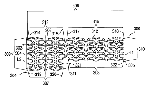
a bifurcated stmt in accordance with the invention. FTr2~
shows a sheet 300 used to form a first expandable tubular member
22
CA 02263008 1999-02-25
301. The sheet 300 has a longitudinal axis 302, a
circumferential axis 303, a proximal end 3u4, a distal end 305, a
first side 306, a second side 307, a third side 308, a fourth
side 309, a fifth side 310, and a sixth side 311. The sheet 300
may be provided with a variety of patterns, however, in a
preferred embodiment the sheet 300 is provided with a plurality
of expandable cells 312 adapted to be substantially flexible
prior to expansion of the first tubular member 301 and
substantially rigid after expansion of the first tubular member
301. In an especially preferred embodiment the flexible cells
312 of the sheet 300 are substantially uniform as shown in FIG.
22.
The first side 306 of the sheet 300 has a proximal portion
313 having a proximal end 314 and a distal end 315. The first
side 3~6 also has a distal portion 316 having a proximal end 317
and a distal end 318.
The second side 307 of the sheet 300 has a proximal end 319
and a distal end 320 and is disposed between the proximal end 304
of the sheet 300 and the distal end 305 of the sheet 300.
The'third side 308 of the sheet 300 has a proximal end 321
and a distal end 322 and is disposed between the distal end 320
of the second side 307 and the distal end 305 of the sheet 300.
The fourth side 309 of the sheet 300 is disposed between the
proximal end 314 of the proximal portion 313 of the first side
306 and the proximal end 319 of the second side 307.
The fifth side 310 of the sheet 300 is disposed between the
23
CA 02263008 1999-02-25
distal end 318 of the distal portion 316 of the first side 306
and the distal end 322 of the third side 308 and is provided with
a length L1 that is shorter than the length L2 of the fourth side
309. In a preferred embodiment, the length L1 of the fifth side
310 and the length L2 of the fourth side 309 are in a ratio of
about 5:7, i.e., the fifth side 310 has a length L1 that is about
70% of the length L2 of the fourth side 309. In an especially
preferred embodiment the sheet 300 is etched with a plurality of
substantially uniform cells 312 as previously discussed and the
number of cells disposed along the circumferential axis 303 of
the fifth side 310 and the number of cells disposed along the
circumferential axis 303 of the fourth side 309 are in a ratio of
about 5:7.
A sixth side 311 is disposed between the second side 307 and
the third side 308. In an especially preferred embodiment, the
first side 306, second side 307, and third side 308 are
substantially parallel to each other and the fourth side 309,
fifth side 310, and sixth side 311 are substantially parallel to
each other and the first side 306, second side 307, and third
side 308 are substantially perpendicular to the fourth side 309,
fifth side 310, and sixth side 311.
To make the first expandable tubular member 301, the second
side 307 of the sheet 300 is attached via attaching means to the
proximal portion 313 of the first side 306 of the sheet 300 and
the third side 308 of the sheet 300 is attached via attaching
means to the distal portion 316 of the first side 306 of the
24
CA 02263008 1999-02-25
sheet 300 to form a first expandable tubular member 301 having a
longitudinal bore 323 defining a longitudinal axis 324 as shown
in FIG. 23. The attaching step may be carried out utilizing a
variety of attaching means well known to those skilled in the art
as suitable for this purpose, however, in a preferred embodiment
the attaching step is carried out utilizing screwing, crimping,
soldering, welding, or spot welding. In the embodiment shown in
FIG. 23 spot welding 325 has been utilized. After the sides have
been attached as discussed above, the fourth side 309 defines a
proximal tubular member aperture or stent aperture 326
communicating with the longitudinal bore 323, and the fifth side
310 defines a distal tubular member aperture or stent aperture
327 communicating with the longitudinal bore 323 as shown in
FIGS. 23 and 26. The sixth side 311 and the proximal end 321 of
the third side 308 and the proximal end 317 of the distal portion
316 of the first side 306 define a side branch aperture 328 (as
shown in FIGS. 23-26) sized and adapted to receive and secure a
second expandable tubular member 329 (shown in FIGS. 26-27). The
branch aperture 328 has a diameter D1 that is larger than the
diameter D2 of the unexpanded stmt, i.e., the branch aperture
328 is larger than the proximal and distal apertures 326 and 327
of the first tubular member 301 both before and after the tubular
member 301 is expanded.
The first expandable tubular member 301 is then delivered to
a bifurcated vessel having a first lumen and a second lumen so
that the first expandable tubular member is disposed within the
CA 02263008 1999-02-25
first lumen and the branch aperture communicates with the second
lumen. In a preferred embodiment, delivery is via a balloon
catheter as previously discussed. After it has been positioned,
the first expandable tubular member is expanded in an amount
sufficient to secure the first expandable tubular member in the
first lumen.
A second expandable tubular member 329 is then prepared
having a proximal end 330 and a distal end 331 and having
longitudinal bore 332 therethrough. The second expandable
tubular member 329 (shown in FIGS. 25, 26, and 27) may be
patterned in the same way as the sheet 300 as previously
discussed. In a preferred embodiment the cells 312 of the sheet
300 used to make the first expandable tubular member 301 and the
cells 312' of the second expandable tubular member 329 are
substantially uniform.
The second expandable tubular member 329 is delivered into
the longitudinal bore 323 of the first tubular member 301, as
shown in FIG. 25, and is advanced into and beyond the branch
aperture 328, as shown in FIG. 26, so that the distal end 331 of
the second expandable tubular member 329 is disposed within the
second lumen and the proximal end 330 of the second expandable
tubular member 329 is disposed within the longitudinal bore 323
of the first tubular member 301. The second expandable tubular
member 329 is then expanded in an amount sufficient to secure the
second expandable tubular member 329 within the second lumen and
within the branch aperture 328 of the first tubular member 301 as
26
CA 02263008 1999-02-25
shown in FIG. 27:
Among the advantages that this embodiment provides is that
this stmt provides a large branch aperture that facilitates the
introduction of the second tubular member into the side branch or
second lumen. In addition, this stent is especially suitable for
the performance of serial bifurcation stenting and also for
stenting around a side branch before it is occluded.
FIGS. 28 to 31 shown an alternative embodiment and
alternative method of making the first tubular member shown in
FIGS. 23-27. In this embodiment the first tubular member 400
(shown in FIG. 29) is comprised of a proximal member 401 having a
proximal end 402 and a distal end 403 and a distal member 404
having a proximal end 405 and a distal end 406 as shown in FIG.
28. The proximal member 401 has a longitudinal bore 415 and is
cut from a first tube 407 having first cross-sectional diameter
D1. The distal member 404 has a longitudinal bore 416 and is cut
from a second tube 408 having a second cross-sectional diameter
D2. D2 is smaller than D1. The tubes 401 and 404 may be etched
or patterned as previously discussed before the proximal member
401 and distal member 404 are cut from the tubes 407 and 408.
Alternatively, the proximal and distal members 401 and 404 may be
etched or patterned after the proximal and distal members 401 and
404 have been cut from the tubes 407 and 408. To make the first
tubular member 400, a portion of the distal end 403 of the
proximal member 401 is attached via attaching means 417 to a
portion of the proximal end 405 of the distal member 404 to form
27
CA 02263008 1999-02-25
a first tubular member 400 having a proximal end 409 and a distal
end 410 and a longitudinal bore therethrough 411 as shown in FIG.
29. The members 401 and 404 may be attached utilizing a variety
of attaching means 417 as previously discussed, however, in a
preferred embodiment the attaching means utilized is welding. In
an especially preferred embodiment spot welding is utilized.
Because D2 is less than D1 the unattached portion of the distal
end 403 of the proximal portion 401 and the unattached portion of
the proximal end 405 of the distal portion 404 define a branch
aperture 412 as shown in FIG. 29 and FIG. 30 (which is an end
view of FIG. 291. In some applications it may be desirable to
have a greater portion of the distal end 403 of the proxim-.1
member 401 and the proximal end 405 of the distal member 404
contact each other before they are attached in order to increase
the strength of the first tubular member 400. This may be
accomplished by, e.g., by distorting, aligning, and contacting a
greater surface area of the distal end 403 of the proximal member
401 and a greater surface area of the proximal end 405 of the
distal member 404 prior to attaching the distal end 403 to the
proximal end 405. FIG. 30A is an end view of this embodiment and
shows that a greater surface area of the distal end 403 and the
proximal end 405 are attached when compared to the embodiment
shown in FIG. 30. FIG. 30A also shows that in this embodiment
the branch aperture 412' is larger than the branch aperture 412
shown in FIG. 30. A second tubular member 413 may then be
introduced into the branch aperture 412 and 412' and as
28
CA 02263008 1999-02-25
previously discussed is expanded and secured so that a portion of
the second tubular member 413 communicates with longitudinal bore
411 to form a bifurcated stmt 414 (shown in FIG. 31).
29