Note: Descriptions are shown in the official language in which they were submitted.
02-MAR-1999 16:52 FRA SLAGTERIERNES FORSKNINGSI TIL 0016132328440 S.05i39
~
Apparatus, tool and method for mechanical removal of a spinal column part from
a part
carcass
The present invention relates to an apparatus for mechanicai removal of a
spinal column part
S from a part carcass, compxising tools for separating the spinal column part
from the part
carcass by cuts along the spinal column part, and conveyor and guide
arrangements for
providing a relative movement between the tools and the part carcass during
cutting.
After splitting pig carcasses, the sides are divided into three parts: the
haxns, middles and
fore-ends. These carcass parts are processed in different ways.
A so-called rib-top sawiing is performed on the middles to remove the spinal
column part. The
operation consists of a x.oanual cuttitng off of the thoracic and lumbar
vertebrae of the spinal
column by means of a circular saw. This cutting leaves bone peaks and ribs in
the meat part.
The spinous processes are also left, if the carcass has not been back-fmned
before splitting.
These bone parts are removed by a manual fnishia,g treatment_
The operator must take great care when making the saw cuts. If too much bone
is left on the
middle, the manual finishing treatment is made more difficult. If, on the
other band, the
operator attempts to avoid bones, valuable meat will be lost along with the
sawn-off bone
parts and the tenderloin muscle may also be damaged.
Various machines for the automatic removal of the spinal column part from
middIes (or loins)
are described in the patent literature. The machines are for the most part
based on one or two
circular saws wYuch saw alongside the bone cutting through the rib heads and
possibly also
the spinous processes, cf. US-A-4_ 134.181 (Schneider), EP-AI-0502.581 (Stork
Protecon),
EP-A1-0627.168 (Stork Protecon-Langen) and EP-Al- 0714_607 (Stork Protecon-
Langen).
DK-A-326/96 (Slagteriernes F'orskningsinstitut) describes the use of aroller
shears, which
avoids formation of meat/bone dust which can cause keeping problems.
A device for the rerxtoval of meat in a single piece firom the spinal column
part and ribs of a
loin from a beef carcass is described in. VVd-Al,-9517825 (The Meat Industry
Research
CA 02263288 1999-03-02
02-MAR-1999 16:52 FRA SLAGTERIERNES FORSKNINGSI TIL 0016132328440 S.06i39
2
Institute of New Zealand). The device comprises a first tool cutting along the
spinous
processes and spinal column, and a second wing shaped tool which separates the
meat from
the ribs. The device produces meat cuts without ribs giving a lower meat yield
than manual
boning.
Fore-ends are treated in a manner which differs from treatment of middles and
loins. They
contain a spinal column part, just as the middles do, but the shape of the
spinal column part
is more complex_ Moreover, fore-ends contain other bones and have a very
complicated
anatomiical structare. It is necessary to use different and more complex
boning techaaiques for
obtaining a high meat yield. Skilled operators are required and their time
consumption is
high.
Various tools have been proposed for extracting the shoulder blade fxom fore-
ends making
the boning processes easier for the operators. However, until now no device
has been
designed for mechanically removal of the spinal column part from fore-ends.
The known
auto=tic devices for rib-top sawing of middles and loins will give a low meat
yield or leave
many bone fragments in the meat if they are used for removal of the spinal
column part of a
fore-end_
The object of the present invention is to provide an apparatus which can
mechanically remove
the spizaZ column part from a part carcass, in particular a fore-end making it
possible to
replace a part of the demaWing work of manual boning with a mechanical
operatiozt, without
decreasing the meat yield which should be on a comparable level with manual
removal of a
spinal column part from a fore-end. Preferably, the apparatus should use at
least one knife
for the mecanical removal thus reducing the amount of sawing dust on the meat.
The above object is achieved by the apparatus according to the invention,
which is
characterised in that it comprises a first cutting tool for mechanically
separating the meat on
the part carcass ffrom the spinous processes and the dorsal side of the spinal
column, said first
cutting tool having a tapering knife blade with a cutting edge along a first
edge and a knife
part along a second edge of the tapering blade, the knilfe part being mounted
mainly at right-
angles to the blade and havizW a cutting edge along the edge closest to the
tip of the tapering
CA 02263288 1999-03-02
02-MAR-1999 16:53 FRA SLAGTERIERNES FORSKNINGSI TIL 0016132328440 S.07i39
3
blade, and that it also comprises a second cutting tool for mechanically
separating the meat
on the part carcass from the lateral side of the spinaal column, said second
cutting tool having
a cutting blade lying mainly in parallel with the tapering blade of the first
tool and being
positioned on the same side of the bIade as the Iazife part.
The apparatus according to the invention is suitable for the mechanical
removal of the spinal
column part from a part carcass, eg. a fore-end, as the two tools can perform
cuts which pass
close to the spinal column bone and can be guided/adjusted so as not to leave
more bone
remnants in the meat than in manual boning. The obtained meat product can
easily be
processed in the abattoir's cutting room so as to produce usual meat cuts,
skin, bone waste
etc. The apparatus of the invention is thus able to perform a considerable
part of the otherwise
complicated and straining nianual boning process.
The cutting edge of the tapering blade in the first tool can cut 1'xee the
spinous processes right
down to their base area while the knife part along the other edge of the blade
cuts along the
dorsal side of the spinal column close to the bone. The tool is designed to
guide along the
bone surface and due to the tapering shape of the blade cutting is from the
base area and
upwards to the top of the spinous processes. When the blade is moved tip-first
it will follow
the line connecting the base areas of the spinous processes, thus cutting
close to the bone. The
blade will always cut on the same (correct) side of the spinous processes even
when the long
processes of a fore-end take various inclined positions.
The second tool cuts along the lateral side of the spinal colunln part,
loosening the bone from
the meat. The second tool may also serve to cut off the ribs from the spinal
column part
separating the spinal bone totally from the meat. If desired, the apparatus
may however
comprise a separate cutting tool for cutting off the ribs from the spinal
column before the
second tool cuts alorzg the lateral side of the bone. This will make the
cutting easier for the
second tool. The separate cutting tool may be a circular saw.
The first and second tools can be guided/adjusted independexltly of each other
enabling the
above mentioned close cuts along the bone and a high meat yield without many
bone remnants
in the meat _
CA 02263288 1999-03-02
02-MAR-1999 16:54 FRA SLAGTERIERNES FORSKNINGSI TIL 0016132328440 S.08i39
4
The tapering blade of the first tool may have a wedge sbape with an angle
between the first
and second edges of the blade of less than 90 , preferably between 20 and 60
.
The first tool may be suspended in units arranged to press the tool into
contact with bones of
the part carcass while the tool is moved (relatively) along the spinous
processes and dorsal
side of the spinal coawmn.
The units may be compressed-air or m,echanical spring units. In this
embodiment the tool
adapts itself automatically to the spinal column, thus cutting close to the
bone.
The apparatus of the invention preferably comprises a resiliently suspended
presser shoe
and/or roller with a contact surface mainly in parallel with the tapering
blade and arranged
to exert a pressure on the meat surface of the part carcass ahead of the
tapering blade while
the tool is performung its cutting work. In this way the maximuzxt amount of
meat is cut from
the neck region. This gives a more correct separation of the spinous processes
and meat
opposite the first cervical vertebrae improving the yield.
The cutting blade of the second tool miay be designed so as to mainly
intersect to the track of
the knife part of the first tool.
The second tool in the apparatus according to the invention may be a circular
saw or similar,
but is preferably a knife blade with a cutting edge along one edge and a blunt
second edge.
It is an advantage to use a knife as this forms only minimum amounts of meat
and bone dust.
The second tool may comprise a knife blade having a curved shape, such as a
cross section
fortxiing an arc of a circle or a flat "V". The width of the knife blade is
preferably between
4 and 12 cm.
The bIade is preferably tapering and bent at an obtuse angle along a line
mainly parallel to
the blunt edge of the blade, preferably at an angle of between 145 and 175 .
When the blade
is tapering, cutting will take place at an inclined angle in relation to the
longitudinal direction
of the spinal column, whereby the spine bone is pressed in to a closer
engagement with a
CA 02263288 1999-03-02
02-MAR-1999 16:54 FRA SLAGTERIERNES FORSKNINGSI TIL 0016132328440 S.09i39
fixing device which may run along the spinal columm. The angled shape of the
blade will
cause the blade to cut more closely into the meat between the two rows of bony
protuberances
on the lateral side of the spinal column.
The knife blade of the second tool is preferably bent at a mainly
pexpendicular angle to the
5 plane of the blade at a distance from the blunt edge of the blade. The edge
which forms the
continuation of the cutting edge along one edge of the blade may be sharpened.
This knife
part is suitable for making a cut along the underside of the spinal coluxnn
opposite the
transverse processes of the cervical vertebra.
The second tool may be designed for cutting off the ribs from the spinal
columm part giving
a minimum amount of meat and bone dust. The apparatus of the invention may
however
comprise a third cutting tool designed for cutting off the ribs from the
spinal colunnn part.
The second tool may be suspended in units which can set the position of the
cutting blade in
a direction at right-angles to the plane of the blade. For example the
apparatus may comprise
a measuring device which directly or indirectly is arranged to measure the
position of a rib
head in a direction at right-angles to the plane of the cutting blade and a
setting device
arranged to set the position of the blade as a function of the measured
position of the rib head.
The membrane on the ribs in a fore-end forms a kind of valley which is widest
at the plane
of separation between the middle and the fore-end and narrows in the direction
of the first rib.
The base of the valley rises up to the first zib, after which it disappears.
It has proved the case
that a satisfactory cut can be obtained when the second tool is set in
relation to the base of the
valley at the first rib.
The apparatus of the invention may comprise a tool for mechanically cutting
the neck bone
strip of a part carcass from the spinal columtt and the side of the transverse
processes.
Between the first and the second cutting tool the apparatus xuay for example
have a tool which
comprises two tapering knife parts mainly at right-angles to each other, said
parts converging
in the direction of the taper end. The cutting tool may have a first guide
surface containing
CA 02263288 1999-03-02
02-MAR-1999 16:55 FRA SLAGTERIERNES FORSKNINGSI TIL 0016132328440 S.10i39
6
the cutting edge in one of the tapering knife parts and a second guide surface
containing the
cutting edge in the second tapering kmife part. The two guide surfaces are
mainly at right-
angles to each other and are suitable for guiding the tool along the underside
of the cervical
vertebrae and the transverse processes_
The conveyor and guide arrangements of the present apparatus may comprise
means for
supporting the spinal column part.
Embodiments of knives and conveyor and guide an-angements are described below.
A method
of using the apparatus is also described below.
The invention also relates to a cutting tool for mechanically separating the
meat on a part
carcass from the spinous processes and the dorsal side of a spinal column
part. The tool is
characterised in that it has a tapering lmife blade with a cutting edge along
a first edge and
a knife part along a second edge of the tapering blade, the knife part being
mounted mainly
at right-angles to the blade and having a cutting edge along the edge closest
to the tip of the
tapering blade.
The tip of the tapering blade is preferably rounded with a radius of between 5
and 20 mm so
that the blade can slide off the spinous processes.
The tapering blade of the tool may have a wedge shape with an angle between
the first and
second edges of the blade of less than 90 , preferably between 20 and 60 .
The part of the knife blade nearest to the edge with the knife part is
preferably bent 2-4 mm
in the direction of the knife parn_ The blade is thus adapted to the shape of
the large spinous
processes.
The blade may have a length of between 5 and 30 cm and a width of between 3
and 12 em.
The lmife paxt may have a width of between 1,0 and 3,0 cm and a length of
between 2 and
cm (i. e. a length of up to the length of the blade)
CA 02263288 1999-03-02
02-MAR-1999 16:55 FRA SLAGTERIERNES FORSKNINGSI TIL 0016132328440 S.11i39
7
The cutting part of the cutting edges may be mainly in the surface planes of
the blade and the
knife part which is designed to face bones of the spinal colurrui part.
The invention also relates to an apparatus connprising a special designed
conveyor and guide
system for the spinal column part during cutting operations, causing a
movement of the part
carcass in relation to cutting tools. The apparatus for mecharxitcal removal
of a spinal column
part from a part carcass, comprising tools for separating the spinal column
part from the part
carcass by cuts along the spinal column part, and conveyor and guide
arrangments for
providing a relative movement between the tools and the part carcass during
cutting, is
characterised in that it comprises a cutting tool for mechanically separating
the meat on the
part carcass from the spinous processes and the dorsal side of the spinal
coIutxui, said cutting
tooI having a tapering knife blade and a knife part which is mounted mainly at
right-angles
to the blade along one edge thereof, and that it also compxises a conveyor
with a motor-driven
endless carrier device with contact faces for bone pazts of the part carcass,
said faces having
sharp projections, and a guide surface for other bone parts of the part
carcass, said guide
surface extending mainly for the length of the conveyor.
The sharp projections are suitable for penetrating bony parts of the spixia.i
coluinn and
effecting a fixing between the spinal column and the carrier arrangement. The
guide surface
is suitable for guiding the spinal column in a plane at eg. right-angles to
the contact surfaces
of the carrier device but may also serve to convey the spinal column in a
fixed m,anner (eg.
by means of a conveyor with a carrier device).
The edge of the tapering blade with the knife part may be placed mainly in
parallel with the
contact faces of the car-rier device and with the guide surface.
The tapering knife blade may be mainly in parallel with the contact faces of
the carrier
device, the laiife part project away from said faces, and the tip of the
tapering blade point in
a direction opposite the conveying direction of the carrier device.
The angle between the contact faces and the guide surface may be between 60
and 900.
CA 02263288 1999-03-02
02-MAR-1999 16:56 FRA SLAGTERIERNES FORSKNINGSI TIL 0016132328440 S.12i39
8
The apparatns may have a roller or belt conveyor opposite the contact faces of
the caxx'ier
device, said conveyor being resiliently suspended and arranged to press bones
of the part
carcass against the sharp projections on the contact faces. The contact
surfaces of the roller
or belt conveyor for the part carcass are preferably driven in the same
direction as the contact
surfaces of the carrier device.
The apparatus may have a roller or belt conveyor opposite the guide surface,
said conveyor
being resiliently suspended and arranged to press bones of the part carcass
against the guide
surface (which may comprise a conveyor having a carrier device with sharp
projections).
The cutting tool may be suspended in units arranged to press the tool into
contact with bones
of the part carcass while the tool is moved (relatively) along the spinous
processes and the
dorsal side of the spiml column.
The apparatus may comprise a further cutting tool for mechanically separating
the meat on
the part carcass from the lateral side of the spinal coluzxui.
Furthermore, the apparatus may comprise a tool for cutting off the ribs from
the spinal
column.
Embodiments of the cutting tool and ftirther tools are described above_ A
method of using the
apparatus is also described below.
The invention further relates to a method for mechanical removal of a spinal
column part
from a part carcass, wherein the spinal colunm part is separated from the part
carcass by cuts
along the spinal column part which are performed by a relative movement
between cutting
tools and the part carcass. The method is characterised in that a mechanical
separation of the
meat on the part carcass from the spinous processes and the dorsal side of the
spbaal column
is effected by means of a first cutting tool with a tapering knife blade with
a cutting edge
along a first edge and a knife part along a second edge of the tapering blade,
the lrnife part
being mounted mainly at right-angles to the blade and having a cutting edge
along the edge
closest to the tip of the tapering blade, whereby the Ioiife blade is guided
along the spinous
CA 02263288 1999-03-02
02-MAR-1999 16:56 FRA SLAGTERIERNES FORSKNINGSI TIL 0016132328440 S.13i39
9
processes and the knife part is moved along the dorsal side of the spinal
coiunm, and that a
mechanical separation of the meat on the part carcass from the lateral side of
the spinal
column is effected by means of a second cutting tool with a cutting blade
which is moved
mainly in parallel with the tapering blade of the first tool and positioned on
tb.e same side of
the blade as the knife part.
The tapering blade used in the method may have a wedge shape with an angle
between the
first and second edges of the blade of less than 90 , preferably between 20
and 60 .
The first tool may be suspended in units arranged to press the tool into
contact with bones of
the part carcass while the tool is moved (relatively) along the spinous
processes and the dorsal
side of the spinal column.
The tapezing blade of the first tool may be moved with the tip and the knife
part close to the
bottom area of the spinous processes.
The cutting blade of the second tool may be moved so as to rnainly intersect
the track of the
knife part on the first tool.
Cutting off of the ribs from the spinal column part may be effected by means
of the second
cutting tool or a third cutting tool.
The spinal column part may be supported during cutting.
During cutting the position of the second tool in a di,rection at right-angles
to the plane of the
spinous processes may be independent of the actual position of the first tool
in the same
direction_
The invention also relates a method for mechanical removal of a spiuzal column
part from a
part carcass, wherein the spinal column part is separated from the part
carcass by cuts along
the spinal column part which are performed by a relative movement between
cutting tools and
the part carcass_ The method is characterised in that a mechanical separation
of the meat on
CA 02263288 1999-03-02
02-MAR-1999 16:57 FRA SLAGTERIERNES FORSKNINGSI TIL 0016132328440 S.14i39
the part carcass from the spinous processes and the dorsal side of the spinal
column is effected
by means of a cutting tool with a tapering knife blade and a knife part which
is mounted
mainly at right-angles to the blade along one edge thereof, whereby the knife
blade is guided
along the spinous processes and the knife part is moved along the dorsal side
of the spinal
5 colunm, and that the relative movement between the cutting tool and the part
carcass is
effected by means of a conveyor with a motox-driven endless carrier device
with contact faces
for bone parts of the part carcass, said faces having sharp projections, and a
guide surface for
other bone parts of the part carcass, said guide surface extending mainly for
the length of the
conveyor_
10 The cuttmg tool used in the method may be suspended in units arranged to
press the tool iuto
contact with bones of the part carcass while the tool is moved (relatively)
along the spinous
processes and the spinal column.
Before cutting, the part carcass may be placed with the rind side on a roller
or belt conveyor
which is mounted opposite the contact faces of the carrier device, said
conveyor being
resiliently suspended and arranged to press the part carcass against the sharp
projections on
the contact faces, and the part carcass may then be conveyed by the conveyor
and guided imo
the gap between the conveyor and the contact faces of the carrier device and
towards the
guide surface.
A part carcass is preferably a fore-end or middle of a pig's carcass. However,
the invention
is not limited to this but may also fmd application in boning a part carcass
from other
azlinials, especially cattles such as cows, calves, bulls, young bulls, sheep
and lambs.
In the present description a part carcass is a meat piece which is obtained by
splitting of a
caxcass and then dividing a produced carcass side in two or more parts by cuts
transversely
to the spinal column part. Typically, part carcasses are: fore-ends, middles
and hams_
The apparatus of the invention has also proved suitable for removing the
spinal column part
from middles and unprocessed Ioins_ It can thus perform two functions in the
abattoir.
CA 02263288 1999-03-02
CA 02263288 2007-07-25
27691-12
11
Cuts which are performed by means of the apparatus and according to the method
of the
invention may be placed more or less closely to the bone, leaving bebind a
greater or lesser
proportion of bone in the meat part. The optimal amount being left in the meat
part depends
on current conditions (price, markets, labour resources etc.)_
A major advantage of the invention is that there is no need to cut through the
spinous
processes which therefore can be removed along with the spinal column.
When two parts are marnly in parallel, this means in the present description
that they rnay be
parallel or form a mutual angle of up to 10-20 . When two parts are mainly at
right-angles
this means that their mutual angle may deviate from a right-angle by up to 10-
20 .
Use of knives for the cuts mentioned will bring significant advantages
compared to circular
saws, as bone and meat dust wzu be avoided, noise levels reduced and
especially as it will
become possible to cut close to the bon.e, because the shape of the knives can
be adapted for
this purpose.
When the blade of the second tool has a curved shape the angle to the blade of
the first tool
is to the medium plane of the curved blade.
CA 02263288 2007-07-25
27691-12
lla
According to one aspect of the present invention,
there is provided an apparatus for mechanical removal of a
spinal column part from a part carcass, comprising tools for
separating the spinal column part from the part carcass by
cuts along the spinal column part, and conveyor and guide
arrangements for providing a relative movement between the
tools and the part carcass during cutting, characterised in
that the apparatus comprises a first cutting tool for
mechanically separating the meat on the part carcass from
the spinous processes and the dorsal side of the spinal
column, said first cutting tool having a tapering knife
blade with a cutting edge along a first edge and a knife
part along a second edge of the tapering blade, the knife
part being mounted mainly at right-angles to the blade and
having a cutting edge along the edge closest to the tip of
the tapering blade, and that the apparatus also comprises a
second cutting tool for mechanically separating the meat on
the part carcass from the lateral side of the spinal column,
said second cutting tool having a cutting blade lying mainly
in parallel with the tapering blade of the first tool and
being positioned on the same side of the blade as the knife
part.
According to another aspect of the present
invention, there is provided an apparatus for mechanical
removal of a spinal column part from a part carcass,
comprising tools for separating the spinal column part from
the part carcass by cuts along the spinal column part, and
conveyor and guide arrangements for providing a relative
movement between the tools and the part carcass during
cutting, characterised in that the apparatus comprises a
cutting tool for mechanically separating the meat on the
part carcass from the spinous processes and the dorsal side
of the spinal column, said cutting tool having a tapering
CA 02263288 2007-07-25
27691-12
11b
knife blade and a knife part which is mounted mainly at
right-angles to the blade along one edge thereof, and that
the apparatus also comprises a conveyor with a motor-driven
endless carrier device with contact faces for bone parts of
the part carcass, said faces having sharp projections, and a
guide surface for other bone parts of the part carcass, said
guide surface extending mainly for the length of the
conveyor.
According to still another aspect of the present
invention, there is provided a method for mechanical removal
of a spinal column part from a part carcass, wherein the
spinal column part is separated from the part carcass by
cuts along the spinal column part which are performed by a
relative movement between cutting tools and the part
carcass, characterised in that a mechanical separation of
the meat on the part carcass from the spinous processes and
the top side of the spinal column is effected by means of a
first cutting tool with a tapering knife blade with a
cutting edge along a first edge and a knife part along a
second edge of the tapering blade, the knife part being
mounted mainly at right-angles to the blade and having a
cutting edge along the edge closest to the tip of the
tapering blade, whereby the knife blade is guided along the
spinous processes and the knife part is moved along the
dorsal side of the spinal column, and that a mechanical
separation of the meat on the part carcass from the lateral
side of the spinal column is effected by means of a second
cutting tool with a cutting blade which is moved mainly in
parallel with the tapering blade of the first tool and
positioned on the same side of the blade as the knife part.
According to yet another aspect of the present
invention, there is provided a method for mechanical removal
of a spinal column part from a part carcass, wherein the
CA 02263288 2007-07-25
27691-12
llc
spinal column part is separated from the part carcass by
cuts along the spinal column part which are performed by a
relative movement between cutting tools and the part
carcass, characterised in that a mechanical separation of
the meat on the part carcass from the spinous processes and
the dorsal side of the spinal column is effected by means of
a cutting tool with a tapering knife blade and a knife part
which is mounted mainly at right-angles to the blade along
one edge thereof, whereby the knife blade is guided along
the spinous processes and the knife part is moved along the
dorsal side of the spinal column, and that the relative
movement between the cutting tool and the part carcass is
effected by means of a conveyor with a motor-driven endless
carrier device with contact faces for bone parts of the part
carcass, said faces having sharp projections, and a guide
surface for other bone parts of the part carcass, said guide
surface extending mainly for the length of the conveyor.
The invention is described in further detail in
the following with reference to the drawings, wherein
- fig. 1A shows the surface bones of a fore-end,
- fig. 1B shows the surface bones seen in the
direction of the spinal column,
- fig. 2A shows a first embodiment of an apparatus
according to the invention for the removal of the spinal
column part from a fore-end,
- fig. 2B shows a cross-section of the apparatus
along line I-I in fig. 2A,
- fig. 3A shows a knife tool in the apparatus,
- fig. 3B shows the tool seen from the side,
CA 02263288 2007-07-25
27691-12
11d
- fig. 4 shows a presser shoe arrangement in the
apparatus,
- fig. 5 shows a second knife tool in the
apparatus,
02-MAR-1999 16;57 FRA SLAGTERIERNES FORSKNINGSI TIL 0016132328440 S.16i39
12
- fig. 6A shows a second embodiment of the apparatus according to the
invention,
- fig. 6B shows a cross-section of the apparatus along line I-I in fig_ 6A,
fig. 6C shows a cross-section of the apparatus along line II-YI in fig. 6A,
and
fig. 7 shows a guiding conveyor.
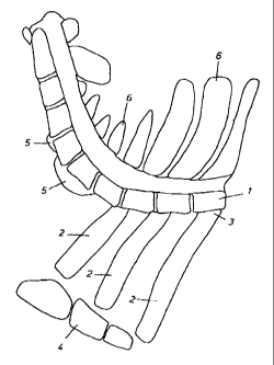
Surface bones
The surface bones of a fore-end comprise the spinal column part 1 and the ribs
2(figs.1A. and
iB). The ribs are connected by their rib heads 3 to the thoracic vertebrae of
the spina), column
and are mutually connected by the stex7num 4.
The cervical vertebrae of the spinal column (the neck bone) have several
transverse processes
5, which together with the vertebrae form a recess for the neck bone strip.
This is a long
muscle running along the cervical vertebrae_
The thoracic and cervical vertebrae of the spinal column have spinous
processes 6 which are
in the symmetrical plane of the carcass. Most often the processes are cut
through
asymmetrically such that the bone mass is non-unifornzl.y distributed on the
right and left fore-
end.
In fig. iB the broad dashed line Si shows the angled cut which is niade by the
first tool in
the apparatus of the invention. The broad dashed line S2 shows the cut which
is made by the
second tool in the apparatus-
First embodiment
The apparatus in figs. 2A and 2B for removal of the spinal colurxtn part from
a fore-end
comprises a conveyor 10 with a belt 11, which serves to support and transport
foxe-end 12.
In fig. 2A the spinal col.uznn of the fore-end is hatched.
Over belt i l is a guide rail 13 which serves to guide the spinal column part
in one plane.
Conveyor 10 is spring-suspended and presses the fore-exxd up against the rail.
A mechanically
CA 02263288 1999-03-02
02-MAR-1999 16:58 FRA SLAGTERIERNES FORSKNINGSI TIL 0016132328440 S.17i39
13
driven endless chain 14 which bas contact plates 15 with spikes forms a side
guide for the
spinal column in another plane. The angle between surface of rail 13 and
contact plates 15
of chain 14 is between 60 and 90 _ If desired, the guide rail 13 tmy be
designed in a similar
way, i.e. have an endless chain with spiked contact plates (and possibly also
an angled guide
rail connecting the two chain systems). A vertical belt conveyor 16 guides the
fore-end
towards the chain 14 and presses the spinal column bone into the spikes on the
contact plates
15. The belt conveyor 16 is spring-suspended to adapt to the fore-end. At its
far end the belt
conveyor passes into pressure rollers 17 which are also spring-suspended. For
the spring
suspension of conveyor 10, belt conveyor 16 and pressure rollers 17,
compressed-air
cylinders may for example be used, the piston rods of which press in a
resilient ntanner on
the fore-end in the direction shown, by the arrows. Instead of compressed-air
cylinders,
mechanical springs with a similar function xnay be used.
The apparatus in figs. 2A and 2B has a first knife tool 18 for separation of
the meat on the
fore-end from the spinous processes and the dorsal side of the spinal column
part. The design
of the tool is shown in figs. 3A and 3B. The tool has a tapering plate 19
(length between 5
and 30 cm; width between 3 and 12 cun) with a fin 20 along one edge close to
the tip of the
plate. The fun is at rigb,t-angle to the plane of the plate and has a cutting
edge along the
vertical or incline edge closest to the tip of the plate 19. The fin projects
1-3 cm from the
plane of pIate 19_ The purpose of the fin is to make a cut along the dorsal
(top) side of the
spinal column. The cut is made when the fore-end resting against guide rail 13
and spiked
plates 15 is moved past the tool, which is held stationary.
The tapering plate 19 has a cutting edge 22 along the other edge, which serves
to cut free the
spinous processes to their base. This is done in the same process as when the
fin cuts along
the dorsal side of the spinal cofurnxa, part. The tapering shape of the plate
means that cutting
can be guided closely along the spinous processes and closely down against the
dorsal side
of the spinal column part.
The tool is actuated preferably by spring or compressed-air units which during
cutting press
it against the spinous processes and down onto the dorsal side of the spinal
colunm part, as
it has a plate part 23 which is fixed to a spring-loaded beam or similar_
CA 02263288 1999-03-02
02-MAR-1999 16:58 FRA SLAGTERIERNES FORSKNINGSI TIL 0016132328440 S.18i39
14
Before the splitting of the carcass, the spinous processes are in some
abattoirs cut free (fxee-
cutting) or the muscles are separated from the spinous processes (blank-
finnin,g). Cutting edge
22 on the tapering plate then serves to complete the free-cutting/separation,
i.e. to cut right
down to the base at the back and neck. However, it is not a condition for the
function of the
apparatus that a prior separation has been made between processes and adjacent
muscles_ The
whole separation can be effected by means of the cutting edge 22 on the
tapering plate.
During cutting with the lmife tool 18, the cervical vertebrae (neck bone) of
the spinal column
are straightened out, as the tool and the following guiding device press the
cervical vertebrae
in the direction of guide rail 13 and chain 14 so that the spinal colunin
finally lies in a straight
line as indicated in fig. 2A.
Ahead of the tool 18 may be mounted a presser shoe device with a contact plate
24, which
during cutting by the tool 18 serves to press down the meat opposite the first
cervical
vertebrae_ The plate can, be connected to a double swing arrn system 25 (fig.
4), which by
means of a compressed-air cylinder 26 presses the plate in the direction of
the fore-end. As
a supplement or replacement to the contact plate, the apparatus may have a
presser roller 24a
for pressing down the meat. The roller is shown by dashed lines in fig. 4_
Immediately behind the knife tool 18 is a guide disk 27 (fig. 2A), which
assumes a position
in the track left by the cutting tool_ The disk holds the spinous processes up
and presses the
spinal coIunm firrnly against the contact plates of the chain and the guide
rail. Fig. 7 shows
an alternative embodioment of a guide device which also serves to convey the
fore-end. The
device or guiding conveyor corxxprises a motor-driven toothed wheel 60 which
engages four
other toothed wheels 61 having a comnnon tangent (dashed line 62). The teeth
of the wheels
61 are sharp and designed to penetrate the bone of the spinal column part
opposite the chain
14 (the device is suspended in spring or compressed-air units pressing it
toward the spinal
bone). The peripbeXal speed of wheels 61 corresponds to the speed of chain 14.
Several
guiding conveyors may be placed opposite chain 14. Alternatively, a guiding
conveyor having
long teeth on one side of a motor-driven chain may be used to guide and convey
the spinal
bone.
CA 02263288 1999-03-02
02-MAR-1999 16:59 FRA SLAGTERIERNES FORSKNINGSI TIL 0016132328440 S.19/39
Behind the disk 27 or guiding conveyor 60, 61 is a second cutting tool 28.
This serves to cut
through the ribs at the rib heads and to separate the meat fronn the lateral
side of the spinal
column part_ The tool has a knife blade 29 which tapers in the opposite
direction to blade 19
in tool 18. At approxinoately the centre, the knife is bent to an obtuse angle
(fig_ 5), such that
5 the cutting edge 30 of the blade can cut close to the bone. In an
alternative embodiment the
knife is curved to follow the bone even closer_ The cross-section of the knife
may eg. be an
arc of a circle. Blade 29 is at its fixing end bent upwards at an angle of
approx. 90 and the
edge which forms the continuation of cutting edge 30 is sharpened. The cutting
edge 31 thus
formed serves to cut along the underside of the spinal column part opposite
the transverse
10 processes of the cervical vertebra.
Tool 28 is fixed firrnly to the apparatus, or if desired it znay be guided in
a forced manner
along a line or curve. The distance from blade 29 to the guide rail 13 may be
set
autornatically for each fore-end.
For this purpose the apparatus may have a measuring device to determine the
optimal cutting
15 position. The device may for exampie sense the base position of the valley-
shaped swrface
formed by the rib membranes.
As the fore-end is carried through the apparatus, a mechanical sensor senses
the distance from
the guide rail 13 to the base of the vailey-shaped surface. When the distance
is at its least (at
the first rib), the optimal cutting position has been found and the distance
of tool 28 to the
guide rail 13 is set in accordance with this. In a simple embod'unent the
measuring device is
merely a mechanical system with a sensor arm connected to a height adjustment
mechanism
of the tool which locks the tool setting at the point where no further
lessening of the distance
to the guide rail is detected.
Blade 29 is mainly in paxallel with the tapedng plate 19 in tool 18, but has a
vertical distance
from the contact surface of the guide rail which is 1-3 cm greater, so that it
is at the same
level as the rib heads of the fore-end. The tip of the blade cuts into the
fore-end such that the
cut maira.ly crosses the track made by fin 20 on lrnife tool. 18. Preferably,
the first tool 18 and
CA 02263288 1999-03-02
02-MAR-1999 16:59 FRA SLAGTERIERNES FORSKNINGSI TIL 0016132328440 S.20i39
16
the second tool 28 are suspended independently of each other enabling cuts
close to the spinal
bone.
In front of the tool 28 the apparatus zxaay have a tool designed for cutting
through the ribs
(preferably rib heads). This will reduce the dennands to the blade of tool 28
and possibly to
the fixing of the fore-end. A circuiar saw niay be used.
Opposite disk 27 or guiding conveyor 60, 61is a too134, which has two knives
at right-angles
which serve to cut the neck bone strip free from the underside and transverse
processes of the
cervical vertebrae, without cutting the strip's connection with the neck
fillet.
When the fore-end has passed all cutting tools, the spinal column part with
spinous processes
has mainly been cut off from the fore-end. The cutting is performed close to
the bone,
providing a good meat yield.
When the tools are guided close to the bone, tips of protuberances and bone
projections are
left behind in the meat. These bone remnants can be removed by normal manual
finishing
treatment.
The knife tools do not cut through the spinous processes, unlike the known
devices for
removing the spinal column part (rib-top) from middles. Consequently, fmishing
treatment
does not require the removal of spinous processes left behind an the meat.
Second enzbodiment
The apparatus in figs. 6A, 6B and 6C for removing the spinal column part from
a fore-end
comprises a resiliently suspended conveyor 40 with a belt 41 for the fore-end
from which the
spinal column is to be removed. Above the conveyor is a fumly fixed conveyor
42 with a belt
43 armed with spikes. These penetrate the spinal colunnn while the fore-end is
conveyed
between the belts. Compressed-air cylinders 44 connected to the suspension of
conveyor 40
press the fore-end up into the spikes. Conveyor 42 has a motor 45, by means of
which the
fore-end can be conveyed with considerable force between belts 41 and 43.
CA 02263288 1999-03-02
02-MAR-1999 17:00 FRA SLAGTERIERNES FORSKNINGSI TIL 0016132328440 S.21i39
17
At the entry end of the conveyor 40 is a vertical belt conveyor 46 for guiding
the fore-end
against a fixed guide rail 47 which extends along the length of the apparatus.
The angle
between the contact faces of belt 43 and guide surface 47 is between 60 and
900. The guide
rail serves as a contact face for the spinal column of the fore-end, as
vertical rollers 48 (fig.
6C) push the fore-end in the direction of the rail_ The guide rail may instead
be designed in
a way similar to the conveyor 42 with a belt armed with spikes (and possibly
an angled rail
connecting the belts of the conveyor systems). Belt conveyor 46 and rollers 48
are mounted
in a yielding ma.ouer so as to adapt to the shape of the fore-end.
The apparatus includes two knife tools of mainly the same design as the tools
18 and 28 in
fig. 2A_ The first tool 49 (fig. 6C) consists of a tapering plate 50 which
along one edge, and
at the tip of the plate, has a fin 51 projecting at right-angles to the plane
of the plate. The fin
is provided with a cutting edge on the edge nearest the tip of the plate. The
other edge of the
tapexi,ng plate is sharpened.
Tool 49 is arranged at such a distance from guide rail 47 and the spiked belt
43 that in a
corresponding way to the tool of the first embodiment it cuts free the spinous
processes and
cuts along the dorsal side of the spinal column at the base of the processes.
Knife too149 has a vertical plate part 52 for fixing the tool on a spring-
loaded beam 53 (fig.
6B). The tool also has a guide part 54 which is part of the tapering plate 50
and seaves to hold
the spinous processes up after they have been cut free and to hold the spinal
column against
the spiked belt and the guide rail. Alternatively, at least one guiding
conveyor of the design
shown in fig _ 7 may be used instead of the guide part 54.
Under guide part 54 is arranged a second knife tool 55. This serves to cut the
ribs and meat
from the spinal colunxn. The tool has a taperi.ttg plate part 56 with a
cutting edge on the edge
of the plate facing the guide rai147. By means of a joining piece 57 the tool
is fixed to a beam
58. Preferably, the beams 53 and 58 are suspended independently. The plate
part 56 has a
vertical (adjustable) distance to the spiked belt 43 of between I and 3 cm.
CA 02263288 1999-03-02
02-MAR-1999 17:00 FRA SLAGTERIERNES FORSKNINGSI TIL 0016132328440 S.22/39
18
The guide rai147 and the spiked belt 42 may be fixed firmly in relation to the
knife tools 49
and 55, but preferably the distance of the tools to the rail and the belt is
altered
(independently) according to need, e.g. according to a previously defined
curve, as a function
of the dimensions of the actual fore-end and/or by using spring or compressed-
air units to
push the tools towards the rail/belt so that they follow the bone surface
themselves _
Other embodiments
The above embodiments of the apparatus according to the invention may also be
used for
removing the spinaI column part from a loin or middle. The distances between
the tools and
the guide surfaces/carriers may differ from in the case of a fore-end.
In the embodiments described, the part carcass (fore-end or middle) is moved
in relation to
stationary knife tools, but the apparatus may instead be designed such that
the part carcass
is stationary while the knife tools are moved. The part carcass may, for
example, be fixed in
position in a stationary fixture.
The apparatus may include other tools than those described here. For example,
it may include
a knife system for cutting off the riblet.
CA 02263288 1999-03-02