Note: Descriptions are shown in the official language in which they were submitted.
CA 02263902 1999-02-23
W 09~ 75~ PCTrUS97/15463
INl'EGRATED THERMA~ PROCESS AND APPARATUS
FOR THE CONTINUOUS SYNTHESIS OF NANOSCALE POWDERS
BACKGROUND OF THE INVENTION
This invention pertains in general to a process and apparatus for the synthesis
of submicron particles. In particular, the invention relates to a novel approachlltili7.ing vaporization and ultra-rapid thermal quenching based on adiabatic expansion
of the vapor through a boundary layer converging-diverging nozzle to produce
0 submicron particles under controlled operating conditions.
As defined in the art, submicron powders are materials havin~ average grain
size below I micrometer. Of particular interest are nanoscale powders. namely,
submicron powders with grain size less than 100 nanometers and with a significant
fraction of interfacial atoms. Of great interest are powders with grain size of less than
15 50 nanometers. Of greater interest are powders with grain size less than 20
nanometers. Of greatest interest are powders with grain size less than 10 nanometers.
It is known that within these size ranges a variety of confinement effects occur that
dramatically change the properties of the material. A property will be altered when
the entity or mech~ni~m responsible for that property is confined within a space20 smaller than some critical length associated with that entity or mech~ni~m. See H.
Gleiter. Mechanical Properties and Deformation Behavior of Materials Havin~ Ultra-
Fine Microstructures~ Nastasi et al. Ed., 3-35 (1993); and R. W. Siegel, Mechanical
Properties and Deformation Behavior of Materials Havin~ Ultra-fine Microstructures.
Nastasi et al. Ed., 509 (1993), which are included herein by reference. Such
25 confinement effects can, therefore lead to a wide range of commercially important
properties. For example, a normally ductile metal will become significantly harder if
its grain size is reduced to the point where moving dislocations through its crystal
lattice are no longer able to occur at norrnal levels of applied stress. Since the stress
required to produce a Frank-Read dislocation is inversely proportional to the spacing
30 between its pinning points, as one skilled in the art would readily understand, a
critical length in this case is that for which the stress necessary to produce adislocation becomes larger than the conventional yield stress for the given metal.
. . , ... .. . .,, .,,.. _ .~ .. ...
CA 02263902 l999-02-23
W 098/09753 PCTrUS97/15463
Thus, confinement effects can be exploited to produce extremely hard and
strong materials with much higher yield stress than exhibited by the conventional
form of their precursors. See Nieman et al., "Mechanical Behavior of Nanocrystalline
Cu and Pd," J. Mater. Res., 6, 1012 ( I g91); and Nieman et al., "Tensile Strength and
Creep Properties of Nanocrystalline Palladium," Scripta Metall. et Mater., 24,145
(1990), which are included herein by reference. The same principle has also beenused to m~nllfActure unique optical materials with grain sizes tailored for excitonic
interactions with particular wavelengths, Skandon et al., "Nanostructured Y,03:
Synthesis and Relation to Microstructure and Properties," Scripta Metall. et Mater.,
o 25, 2389 (1991); electroceramics with unique electronic and electrical characteristics,
F.~.ctm~n et al., "Processing and Properties of Nanophase Oxides," Mater. Res. Soc.
Symp. Proc., 155,255 (1989); superplastic ceramics with grain sizes engineered to
allow low cost, rapid net-shape forming of ceramics as a substitute process for
m~f~hining of ceramics, H. Hahn et al., "Low Temperature Sintering and Deformation
of Nanocrystalline TiO~," Mater. Res. Soc. Symp. Proc., 196, 71 (1990) and M. J.Mayo, Mechanical Properties and Deformation Behavior of Materials Havin Ultra-
fine Microstructures, Nastasi et al. Ed.,361 (1993); catalysts with extremely high
surface areas, high selectivity and activity, Beck and Siegel, "The DissociativeAdsorption of Hydrogen Sulfide over Nanophase Titanium Dioxide," J. Mater. Res.,7, 2840 (1992); materials with unique electrochemical properties, Tamaki et al.,"Grain-Size Effects in Tungsten Oxide-Based Sensor for Nitrogen Oxides,"
J. Electrochem. Soc., 141,2207 (1994); and materials that exhibit unprecedented
magnetic properties, Sugaya et al., "Soft Magnetic Properties of Nanostructure-
Controlled Magnetic Materials," IEEE Trans. on Magnetics,31,2197 (1995) and C.E.Yeack-Scranton, Nanoma~netism~ Kluwer Academic, Netherland, 1-6 (1993), all of
which are included herein by reference. Quantum confined and nanometer cluster
m~teri~l~, therefore, are an extraordinary opportunity for design, development and
commercialization of a wide range of structural, electrochemical, electrical, optical,
electronic, magnetic and chemical applications. Furthermore, since they represent a
whole new family of material precursors where conventional coarse-grain
physiochemical mech:~ni~m~ are not applicable, these materials offer a unique
CA 02263902 l999-02-23
WO ~a~s~ PCTAUS97/15463
combination of properties that can enable novel and multifunctional components of
nm~tçhed performance.
Although this opportunity has been apparent for several years, large scale
commercialization has remained unrealized because of the high cost and low
5 throughput of existing processes for producing nanopowders, the current lack of
process control over size and size distribution of the resulting material, the
unpredictable composition of its constituent phases, and the lack of control over the
nature of and the interactions arnong the interfaces created between the constituent
phases. Nanopowders may indeed represent the threshold of a new era in materialsI o technology, but the key to their full utilization depends on the development of new
processes for producing nanopowders economically and in commercially viable
quantities under controlled operating conditions.
In recent years, several methods have been used for producing nanopowders
and the materials produced by this prior-art technology have confirmed the fact that
5 nanopowders possess important technical properties that show the potential forbccoming commercially significant. However, all known production methods consistof batch processes that are too expensive to yield commercially affordable materials
for bulk applications (current production costs for these processes are orders of
magnitude higher than the $1 0.00/lb target price considered economical for bulk20 applications of these materials). Therefore, the commercial future of nanopowders
depends on the development of a process that can produce nanopowders with
predetermined properties, in commercially viable quantities~ and at an affordable cost.
An additional and significant problem encountered by the performance
ceramics industry is the use of environment~lly undesirable solvents and additives
25 (acids, alkalis, ammonia and aromatic dispersants to name a new examples) in large
quantities. Unfortunately, the present processing techniques continue to require the
use of solvents and additives and the anticipated growth in this market for ceramic
devices suggests that this environmental hazard will only increase.
Ideally, the synthesis and processing technology for nanopowders should
30 allow control of the size and size distribution of the constituent structures and phases
(this is critical to the mechanistic perforrnance of nanopowders); allow control of the
composition of the phases in the nanomaterial (critical to define the property domain
CA 02263902 1999-02-23
W 098~ 75~ PCTrUS97/15463
of the nanomaterial); allow control over the nature of interfaces (e.g. purity) and the
interaction between interfaces (critical to the interface-based characteristics of the
nanopowders); and minimi7~ the use of environmentally undesirable solvents and
additives. None of the known processes for the synthesis of nanomaterials possesses
5 these characteristics; therefore, none is suitable for bulk commercialization of
nanopowders.
In particular. prior-art processes are all batch, and have high energy or solvent
processing requirements, which are all inherent limitations to the cost-effective and
large-scale production of nanopowders. The processes currently in use can be
o classified into three general groups: chemical, mechanical-attrition, and gas-condens~tion methods. The chemical methods include precipitation techniques, sol-
gel processes~ and inverse-micelle methods. See Beck and Siegel, "The Dissociative
Adsorption of Hydrogen Sulfide over Nanophase Titanium Dioxide," J. Mater. Res.,7, 2840 ( 1992), and Steigerwald and Brus, "Synthesis, Stabilization, and Electronic
Structure of Quantum Semiconductor Nanoclusters," 1 1 Ann. Rev. Mater. Sci., 191471 (1989), which are included herein by reference. These processes have been used
to successfully synthPci7e narrowly distributed nanopowders; howeven being
chemical-media based, the resulting nanopowders are covered with chemical surface
layers. This surface covering adversely affects the properties of the nanopowders and
20 inhibits their further processing into bulk materials. In addition, the use of solvents
and chemicals has a significant economic impact on the synthesis process because of
the costs of chemicals and. as ~ cn~ced above, the pollution remediation required by
their use.
The mechanical attrition methods rely on the physical decomposition of
25 coarser grains through severe mechanical deformation. Such processing methods are
energy intensive, have low flexibility, are susceptible to cont~min~lion by attrition
tools or media, and afford little control over the quality and con.~i~te~ry of the final
product.
The gas con(len~tion methods essentially involve the evaporation of a coarse
30 (at least micron size) source of precursor material, such as a metal, inorganic, etc., in
an inert gas at a low plt;S:iul~. The evaporated source atoms or molecules collide with
the gas atoms or molecules and lose energy, thereby causing a homogeneous
CA 02263902 1999-02-23
W O 98/09753 PCTrUS97/15463
condensation of atom or molecule clusters in the supersaturated vicinity of the
precursor source. The further accretion and/or coalescence of the nucleated particles
is minimi7f d by rapid removal ofthe nanometer-sized powders so forrned from theregion of supersaturation. See R. Uyeda, "Studies of Ultrafine Particles in Japan:
5 Crystallography7 Methods of Preparation and Technological Applications," I I Prog.
Mater. Sci., 35, 1 (1991), and R. W. Siegel, Materials Science and TechnoloF~y, 15,
VCH, Weinhem, 583 (1991), which are incorporated herein by reference.
Alternatively, gas condensation processes may involve gas-phase reactions. some of
the known gas con(len~tion processes have produced nanomaterials of acceptable
10 size distribution, but they are all batch operations and are not readily scaleable for
commercial exploitation.
Additionally, rapid solidification processing of high temperature liquids and
vapors has been extensively researched. See Loren A. Jacobson and J. McKittrick,"Rapid Solidification Processing ", Materials Sciences & Eng., R-l 1, 355-408 (1994),
5 which is incorporated herein by reference. Such process techniques are used toprepare fine microstructures (micron sized), increase solid solubility of alloy
elements, and prepare non-equilibrium phases, particularly in powder metallurgy.Conventional rapid solidification methods, such as oil quench, gas quench, chillcasting, and centrifugal atomization, achieve therrnal quench rates of I o2 to 105KJsec.
Higher quench rates are very desirable because they can enable the synthesis
of powders that are submicron in domain size and, at rates greater than I o6 K/sec7 can
enable the synthesis of powders with domain size less than 100 nanometers. As
defined in the art, submicron powders are materials having average grain size below I
25 micrometer. Of particular interest are nanoscale powders; namely, submicron
powders with grain size less than 100 nanometers. Finer domain sizes are desirable
because the physiochemical properties of materials are remarkably different and
commercially useful when the domain size is reduced below 100 nanometers.
Nanoscale powders also exhibit very high surface areas and enh~nced surface activity
30 for physical and chemical reactions.
To achieve higher cooling rates, contact qllen~hing methods such as splat
cooling and glazing have been suggested. See Jones, "Splat Cooling and Metastable
CA 02263902 1999-02-23
W 098~'0~75~ PCT~US97/1~463
Phases," Rep. Progr. Phys.,36,1425 (1973), which is incorporated herein by
reference. However. these methods are not suitable for thermal 4uenching of hightemperature vapors (greater than l S00 K) because these temp~ldLu,~s lead to
thermokinetic transformations from reactions at contact surfaces. These methods are
5 also not useful for high temperature vapors of materials such as carbides, nitride,
refractory metals, alloys, and multiphase nonequilibrium phases because the hightemperatures can irreversibly damage the contact surfaces. Furthermore, these prior-
art methods are not suited for thenn~lly quenching high telllpclalllre~ chemically-
active vapors ~such as those resulting from chemical reactions between feed
lo components at high temp~ldtu~es).
U. S. Patents 5,407,458,5,403,375, 5,384,306, and 5,389,585 by Konig et al.
all describe the production of nanoscale powders using a process of the reaction of
chemically active vapors between feed components at high temperatures. The
corresponding metal compounds and corresponding reactants are reacted in the gas15 phase in a reactor at a temperature of 2000 degrees C or lower, homogeneouslycon-lPn~ed directly from the gas phase in the absence of any wall reactions and
subsequently removed from the reaction medium. It is asserted that, by separately
preh~ ting the process gases to at least the reaction temperature, the nucleation site
can be confined. A flow optimized hot wall reactor is used as the source because it is
20 believed by KBnig et al that other sources such as a plasma flame or laser beam result
in uncontrollable reaction conditions prevailing in various parts of the reaction zone
with very steep tt;~ ucldl~lre gradients and/or turbulent flow conditions, resulting in
the powders having broad particle size distribution. The nozzle in the Konig et al.
process relates to feed system ofthe process and does not merh~ni~tically participate
25 with the evaporation, reactions, con-l~n~tion or growth of fine powders. Mostnotably, because the process described by Konig et al. is a reactive process,
byproducts such as HCI are formed, which ultimately affect the purity of the
nanomaterials. Because their temperature is limited to 2000 degrees, the process is
limited to precursors that have a vaporization temperature less than 2000 degrees C.
30 In addition, Konig et al. teach a laminar flow technique that would face scale up
limitations. rhis is so because the powder characteristics are related to residence time
of gases in the reactor, which in turn is related to the parabolic flow associated with
CA 02263902 1999-02-23
W O 9~ PCTrUS97/15463
laminar flow. In other words, in the Konig et al. process~ there is a radially varying
profile in residence time (the gas at the center is moving faster than the gas near the
wall). As the reactor is scaled up, the powder size will get more broad in distribution.
.
Therefore, there continues to be a need for a low-cost process (less than
$1 0/lb) that is suitable for large-scale production of nanopowders under controlled
operating conditions. The present invention discloses a pioneering and unique
therrnal cond~n~tion process. This process can be a strictly physical process which
starts with a material, vaporizes it at very high temperatures (above 2000 degrees C),
0 then very rapidly recondenses it to produce nanoscale powders, thus elimin~ting the
forrnation of undesirable byproducts. This process satisfies these requirements for the
continuous production of nanopowders in bulk quantities, and additionally discloses a
Joule-Thompson nozzle that is particularly suited for ultra-rapid quenching and
conrl~n~tion of vaporized material described above.
1s
SUMMARY OF THE INVENTION
One of the objectives of this invention is a low capital-cost process for the production
of quantum confined and nanometer cluster materials of various inorganic
20 compositions including but not limited to carbides, nitrides, oxides, chalcogenides,
halogenides, alloys, metals, complex compositions, and composites in bulk quantities.
Another objective of this invention is to develop techniques to control the size, shape,
2s surface area, morphology, surface characteristics, surface composition, distribution,
and degree of agglomeration.
Another objective ofthe invention is a device that enables very high quench rates of
high te~ c~d~ule vapors that can produce nanoscale powders.
CA 02263902 1999-02-23
W0981'~7~ PCT~US97/15463
Yet another objective of this invention is to develop a method of preventing thedeposition of the quantum confined and nanometer cluster materials on the walls of
the process equipment.
5 Another objective is to develop a process which allows vaporization of ingredients at
very high temperatures (> 2000 degrees C) yet permits quenching at very high rates.
Yet another objective is to develop a process which produces product but generates
no byproduct.
0
A further objective of this invention is to develop a method of ensuring high yie}d and
high selectivity, including but not limited to harvesting 95% + of the quantum
confined and nanometer cluster material produced.
15 Yet another objective of this invention is to prevent the damage of the quantum
confined and nanometer cluster materials during and after their synthesis.
Another objective is a device that is simple, easy to operate, and flexible with respect
to operating parameters, so as to allow the production of multiple products.
Another objective is a device that prevents cont~min:ltion of the quenched product
from the materials of construction used for the quench equipment.
Yet another objective is a device that allows flexibility in the composition of the
25 vapor q~ n(~.h~l, in quench rates and quench volume.
Another objective of the invention is a process and device that can be carried out with
low utility costs (that is, low energy input, energy output, and m~inten~nce expenses).
30 Another objective is a process and device with low operating costs (i.e., labor,
recycling, raw materials, plant space, etc.); accordingly, the invention aims at a
process and device with high yield per pass and high product selectivity.
CA 02263902 l999-02-23
W 098/09753 PCT~US97/15463
Another objective is a process that is continuous and suitable for scaling up toproduction rates in the order of tons per day.
~ Yet another objective is a process that is simple, easy to operate. and flexible~ so as to
5 allow the production of multiple products with relatively simple operating changes.
Still another objective is a process and device that are safe and environrnentally
benign.
10 Finally, another objective is an operationally stable process that requires a minim~l
external-control structure for steady-state operation.
A process that satisfies most of these features would be very desirable because
it would enable the economical manufacture of nanopowders in bulk quantities.
I s Therefore, according to the foregoing objectives, one aspect of the this invention
involves the continuous vaporization at very high temperatures of commercially-
available, coarse precursor material suspended in a carrier gas in a therrnal reaction
chamber under conditions that minimi7~ superhe~ting and favor nucleation of the
resulting vapor. Optionally, a kinetic gas feed may be mixed with the vapor in the
20 reactor to reach a thermokinetic state of the vapor that may be required to produce
controlled nucleation of solid powders from the vapor stream. Immediately after the
initial nucleation stages, the vapor stream is rapidly and uniformly quenched at rates
of at least 1,000 K per second, preferably greater than 1,000,000 K per second, to
block the continued growth of the nucleated particles and produce a nanosize powder
25 suspension of narrow particle-size distribution. The nanopowder is then harvested by
filtration from the quenched vapor stream and the carrier medium is purified,
compressed and recycled for mixing with new precursor material in the feed stream.
According to another aspect of the invention, the thermal quen~hing is carried
out in a converging-diverging expansion nozzle that exploits the Joule-Thompson
30 principle of adiabatic expansion of high-temperature vapors. Since the physical
characteristics of the nozzle determine the extent of cooling, pressure drop anddensity drop, the con~ien~;ltion process can be advantageously controlled by ntili7.ing
CA 02263902 1999-02-23
W 0981'~3753 PCTrUS97/lS463
a nozle of predetermined key dimensions to fit the requirements of the material being
condensed.
Various other purposes and advantages of the invention will become clear
from its description in the specification that follows and from the novel features
5 particularly pointed out in the appended claims. Therefore, to the accomplishment of
the objectives described above, this invention consists ofthe features hereinafter
illustrated in the drawings, fully described in the detailed description of the preferred
embodiments and particularly pointed out in the claims. However, such drawings and
description disclose only some of the various ways in which the invention may beo practiced.
CA 02263902 1999-02-23
W 098/09753 PCT~US97/15463
BRIEF DESCRIPTION OF THE DRAWINGS
Figure I is a schematic representation of the adiabatic-expansion, thermal quenching
process of the present invention.
Figure 2a is a sketch of a converging-diverging nozle illustrating the relationship
between critical parameters of the process and of the nozzle used to carry out the
nventlon.
0 Figure 2b is a sketch of a converging-diverging nozzle illustrating the key design
pararneters of the device.
Fig~lre 3a, 3b and 3c are cross-sectional elevational, top, and cross-sectional
elevational drawings, respectively of a converging-diverging, adiabatic expansion
s nozzle according to the preferred embodiment of the invention.
Figure 4 is a sçhem~tic illustration of a pilot-plant process according to the preferred
embodiment of the invention.
20 Figures 5a, 5b, 5c, and 5d are drawings ofthe preferred embodiment ofthe present
invention for a scaled up process.
Figure 6 is the tr~n.cmiccion electron micrograph of the zinc nanosize powder
produced by the invention.
2s
Figure 7 is an X-ray diffraction patters of the product of Example I, indicating that
the only phase present was zinc.
Figure ~ is a SEM micrograph of the feed powders iron and titanium used, showing30 that they were greater than 1 micrometer when fed.
CA 02263902 1999-02-23
W O 98~1S~ PCT/US97/15463
.
Figure 9 is a tr~n.cmi~cion electron microscope image of the iron-titanium alloynanopowders produced in Example 2, showing them to be in the 10-45 manometer
range.
5 Figure 10 is an X-ray diffraction pattern of the product of Example 2, indicating that
the phases formed were titanium, iron and iron-titanium intermetallic.
Figure 11 is a tr~ncmiccion electron microscope image of the nickel aluminide
nanopowder produced in Example 3.
Figure 12 is an X-ray diffraction pattern of the product of Example 3, indicating that
the phase formed was NiAl.
Figure 13 is a tr~n~miccion electron microscope image of the tungsten oxide
s nanopowder produced in Example 4.
Figure 14 is an X-ray diffraction pattern of the product of Example 4, indicating that
the phase formed was W O3.
20 Figure 15 is a tr~n.cmiccion electron microscope image of the cerium oxide
nanopowder produced in Exarnple 5.
Figure 16 is an X-ray dif~action pattern of the product of Example 5, indicating that
the phase formed was CeO~.
Figure 17 is a tr~n.cmi.ccion electron microscope image of the silicon carbide
nanopowder produced in Example 6.
Figure 18 is an X-ray diffraction pattern of the product of Example 6, indicating that
30 the phase formed was SiC.
. . .
CA 02263902 1999-02-23
W O ~3~ 7~ PCTrUS97/15463
Figure 19 is a tr~ncmi~ion electron microscope image of the molybdenum nitride
nanopowder produced in Example 7.
Figure 20 is an X-ray diffraction pattern of the product of Example 7, indicating that
5 the phase formed was Mo2N.
Figure 21 is a sc~nning electron microscope image of the nickel boride ceramic used
in Example 8, showing that the feed powder was greater than I micrometer.
o Figure 22 is a tr~n~mi~ion electron microscope image of the Ni and Ni3B
nanopowders produced in Example 8, showing them to be in the 10-30 manometer
range.
Figure 23 is an X-ray diffraction pattern of the product of Example 8, indicating that
15 the phases forrned were Ni and Ni3B.
Figure 24 is a tr~n~mi~.~ion electron microscope image of the calcium-oxide
nanopowders produced in Example 9, showing them to be in the 5-20 manometer
range.
Figure 25 is an X-ray diffraction pattern of the product of Example 9, indicating that
the phase formed was CaO.
Figures 26a and 26b are trRn~mi~ion electron microscope micrographs of bariurn
25 titanate produced in Example 10.
Figure 27 is an X-ray diffraction pattern of bariurn titanate produced in Example 10.
Figures 28a and 28b are tr~n~mission electron microscope micrographs of ~ Liu
30 titanate produced in Example 10.
CA 02263902 1999-02-23
W O 98/09753 PCT~US97/15463
Figure 29 is an X-ray diffraction pattern of strontium titanate produced in Example
10.
Figures 30a and 30b are tran~mi~.~ion electron microscope micrographs of barium
5 titante produced in Example 10.
Figure 31 is an X-ray diffraction pattern of barium titanate produced in Example 10.
Figure 32 is a tr~n.~mi~sion electron microscope micrograph of nickel zinc ferrite
lo produced in Exarnple 11.
Figure 33 is an X-ray diffraction pattern of nickel zinc ferrite produced in Example
I 1 .
15 Figures 34a and 34b are tr~ncmi.s~ion electron micrographs of Ni/Cr/Co/Mo alloy
produced in Example 12.
Figure 35 is an X-ray diffraction pattern of Ni/Cr/Co/Mo alloy produced in Exarnple
12.
Figure 36 is a tr In.~mi~cion electron micrograph of bismuth telluride produced in
Example 13.
Figure 37 is an X-ray diffraction pattern of bismuth telluride produced in Example 13 .
CA 02263902 1999-02-23
W O 9~0~7~ PCTrUS97/15463
DETAILED DESCRIPTION OF THE INVENTION
A primary aspect of this invention lies in the discovery that the size and size
~ distribution of nanopowders produced by vapor condensation can be controlled by
5 interrupting the growth process through ultra-rapid thermal quenching of the
condensing vapor. Another critical aspect of the invention is the realization that
Joule-Thompson adiabatic expansion provides a controllable process for quenchingsuch con~1~n~ing vapor at predetermined rates as high as I o6 ~C/sec, or greater, as
required for producing nanopowders of desired properties. A third, important aspect
o of the invention is the development of a converging-diverging nozle to implement
the adiabatic expansion process of the invention under predictable conditions for a
variety of precursor materials and operating conditions.
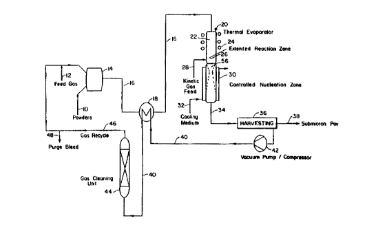
Referring to the drawings, wherein like parts are designated throughout with
like numerals and symbols, Fig. l shows the process flow diagram and a srhem~tics representation ofthe apparatus ofthe invention as applied to solid precursors, such as
metals, alloys, ceramics, composites, and combinations thereof. It is understood that
the process applies equivalently to other forms of precursors such as liquid, gaseous,
slurry, and combinations thereof. A feed stream 10 of such a ple~ o~ material inpowder form is premixed with a feed gas stream 12 (such as argon, heliurn, nitrogen,
20 oxygen, hydrogen, water vapor, methane, air, or a combination thereof, depending on
the particular precursor being processed and the corresponding atmosphere - inert,
oxidizing, or reducing - required for the process) in mixing apl)~dlus 14 appl~,pl;ate
to create a suspension. It is preferred that the feed be a low-cost, coarser form of
composition desired. However, if the coarse forrn is expensive, it is equally feasible
25 to use a mix of low-cost precursors that when combined reflect the composition
desired. While stoichiometry is preferred, non-stoichiometric feed ratios can be used
if the non-stoichiometric feed is less expensive or if the final product streams have the
properties as desired. The feed can be a pure composition, a mix of solids and
reactant gases, a mix of solids and reactant liquids, a mix of solids, a mix of liquids
30 and gases, a mix of liquids, a mix of gases, a mix of solids, liquids and gases, or
combinations thereof. In one preferred embodiment, essPnti~lly the only conctitllent
atoms present in the feed other than inert components are the constituent atoms
CA 02263902 1999-02-23
WO 98~57~3 PCT~US97115463
present in the desired solid product. There may be very minor impurity atoms in the
feedt but undesired atoms are not present to any significant extent. As an example, if
the desired oxide product is nanoscale zinc oxide (ZnO), the feed would be micron
scale zinc oxide. If the desired product is indium tin oxide (ITO) the feed would be
5 indium oxide and tin oxide. If the desired product is nonstoichiometric titanium
dioxide. the feed would be titanium dioxide and the process would be run to produce
a non-stoichiometric product. An example of a system which would not ~ es~ this
embodiment would be the reaction of titanium tetrachloride with water to producetitanium dioxide and hydrogen chloride as follows:
TiCI4 + 2H2O --------> TiO~ +4HCI (l)
In this case there are constituent atoms present in the feed. namely hydrogen and
chlorine, which are not present in the desired solid product.
The preferred method is premixing the feed to as homogeneous levels as
possible. ~owever, heterogeneous, series. or parallel feeds are suitable for certain
applications. The feed precursors are preferably carried in a gas or a mix of gases that
does not possess or can contribute an element that is not desired in the final
composition. A preferred carrier stream are inert gases such as argon, heliurn, neon
20 and xenon. The powder 10 is then suspended in the gas l 2, preferably in a
continuous operation, using fluidized beds, spouting beds. hoppers. or combinations
thereof, as best suited to the nature of the precursor. The test runs perforrned to
reduce the invention to practice were conducted with precursor feeds having particle
size greater than 1 micrometer, but the process could be used with any size suitable
25 for its continuous vaporization in a gas stream. The resulting gas-stream suspension
16 is advantageously plclleated in a heat exchanger 18 and then is fed into a therrnal
reactor 20 where the suspended powder particles preferably completely evaporated in
a therrnal evaporation zone 22 by the input of thermal energy. The dimensions of the
hot zone are established based on energy balance equations derived from basic
30 principles of transport phenomena. The telllpe,~Lu,~ histories of the feed material
depend upon the enthalpy of the plasma discharge and the thermodynamic properties
of the feed m~teri~l The times required for heating the particulate material to the
16
CA 02263902 1999-02-23
W O ~ 5/~ PCT~US97/15463
melting point, melting, heating to the vaporization point and vaporization are
calculated using heat transfer equations. Additionally, the steps of heating up to the
melting temperature and boiling point. and melting and vaporization can be described
~ using a~ ".ate heat transfer equations. These equations can be found in the U.S.
Provisional patent application Express Mail number EI813191 155US dated August
26, 1997, and in Transport Phenomena in Mettalurgy, G.H. Geiger and D. R. Pourier,
Addison-Wesley Publishing Co., Reading, MA, USA (1973) both of which are
included herein by reference. The source 24 of such therrnal energy can be
accomplished by external heat transfer or by internal heat or both. Examples of
lo external heat include but are not limited to induction, d.c. arc, plasma and radiation.
Examples of internal heat include, but are not limited to reaction heat such as
combustion and latent heats of phase transformation. Any of these may be used solong as they are sufficient to cause the rapid vaporization of the powder suspension
being processed. It is desirable that the te."pe,dlure in the thermal evaporation zone
be in excess of 2000 degrees C. It is p,~f~ ,d that the t~l.p~dl lre in the thermal
evaporation zone be in excess of 3000 degrees K. It is more preferred that the
temperature in the thermal evaporation zone be in excess of 4000 degrees K. It is
most preferred that the T in the thermal evaporation zone be in excess of 5000 degrees
K. It is necessary that the t~-"~G,dlure in the thermal evaporation zone be above the
vaporization t~mpclalul~ of all constituent species. Optionally, in order to prevent
cont~rnin:~tion of the vapor stream caused by partial sublimation or vaporization of
the thermal reactor's interior walls, they may be pre-coated with the same material
being processed. Additionally, this problem can be prevented most preferably by
actively cooling the reactor walls and by using a confinement gas stream, i.e. ablanket of the inert gases along the walls of the reactor.
The vaporized gas-stream suspension next enters an e~t~nt1ed reaction zone 26
of the thermal reactor that provides additional residence time, as needed to complete
the evaporation of the feed material and to provide additional reaction time (ifnecessary). It is desirable that the telllp~,lalule in the extended reaction zone be in
excess of 2000 degrees C. It is preferred that the temperature in the extended reaction
zone be in excess of 2500 degrees K. It is more preferred that the t~ p~,dl~lre in the
extended reaction zone be in excess of 30no degrees K. It is necessary that the
.. ~ .. . . . .. ..
CA 02263902 1999-02-23
W 098/09753 PCTrUS97/15~63
temperature in the extended reaction zone be above the vaporization temperature of
all constituent species. In some cases, this may m~ncl Ite a temperature in excess of
3000 degrees K. As the stream leaves the reactor, it passes through a zone 56 where
the thermokinetic conditions favor the nucleation of solid powders from the vaporized
5 precursor. These conditions are deterrnined by calculating the supersaturation ratio
and critical cluster size required to initiate nucleation. Rapid quenching leads to hig~h
supersaturation which gives rise to homogeneous nucleation. The unstable vapor
phase system self-nucleates on atomic clusters of critical size. Below the critical size,
the clusters are unstable for a given supersaturation, while above the cluster size the
10 free energy of the cluster is negative. For an ideal vapor phase, the radius of the
critical cluster size is given by the relation
rn = 2yV/kTln(P,/P~) (2)
15 where ~y is the surface free energy, V is the molecular volume of the condensed phase,
k is Boltzman's constant, P, is the pressure of the vapor in the system, and P~ is the
vapor pressure of the condensed phase. See G. S. Springer, Advances in Heat
Transfer,14, 281-341, Academic Press (1978) which is included herein by reference.
Using titanium powder as an example, based on the physical properties of the
20 feed material and operating conditions in the reactor (size = 1 O~L, melting point =
l ,660 ~C, boiling point 3,287 ~C, heat of vaporization of titanium = 10.985 Btu/g, hot
gas temperature = 4,000 ~C), it is possible to calculate the residence time required for
vaporization (2.32 msec for heating to melting point, 0.265 msec for melting,5.24
msec for vaporization; total time required = 8-10 msec). Based on the velocity of the
25 suspension injected into the reactor and the travel distance through the reactor, one
can ~letennine that a velocity of about 46 ft/sec produces a reci~ence time of 10.7
msec, sufficient for ~oli~lion. If the process requires a predetermin~-d
thermokinetic state of the powder being processed which can be enh~ncecl by the
presence of a particular gas, a kinetic gas feed 28 (such as argon, helium, nitrogen,
30 oxygen, hydrogen, water vapor, methane, air, or combinations thereof) can also be
mixed with the precursor vapor to reach the desired thermokinetic state. As soon as
the vapor has begun nucleation, the process stream is quen~hPd in a converging-
CA 02263902 1999-02-23
WO ~ 57a~ PCT/US97/15463
diverging nozzle-driven adiabatic expansion chamber 30 at rates at least exceeding
103 K/sec, preferably greater than I o6 K/sec, or as high as possible. As further
detailed below, a cooling medium 32 is utilized for the converging-diverging nozzle
to prevent cont~min~tion of the product and damage to the expansion chamber 30.
s Additionally, the use of a confinement blanket gas stream all along the periphery of
the product stream also prevents the deposition of nanometer clusters to the walls of
the reactor from thermophoresis. Rapid qllen~hing ensures that the powder produced
is homogeneous, its size is uniform and the mean powder size remains in submicron
scale. The quenrhing of the product gas, however, can be accomplished in numerous
o ways and combinations thereof. Some additional examples include, but are not
limited to, addition of coolant gases or liquids. addition of materials which absorb
heat, radiative cooling, conductive cooling, convective cooling, application of a
cooled surface, impinging into liquid such as but not limited to water. The preferred
method however, is gas expansion as is described in detail below.
I s The theoretical behavior of the Joule-Thompson adiabatic expansion process is
described by the well-known equation:
T,/T, (P2/P,) , (3)
20 where T, and T2 are the temperatures before and after expansion, respectively; P, and
P2 are the pressures before and after expansion, respectively; and k is the ratio of
specific heats at constant pressure and constant volume (C,JCV).
Applying Equation 2 to a t~ p~ldlUlC change occurring during adiabatic expansion,
25 AT,
AT/T~ = (T2 - T,)/T~ = (P2/p~) (k-lyk_ 1; (4)
or, for a steady state process,
dT/dt = T, d[(P,/P,) (k-'Yk]/dt, (5)
19
CA 02263902 1999-02-23
W O 981'~ 3 PCTrUS97/lS463
which suggests that Joule-Thompson expansion can quench high-t~ p~,dlure vapors
at a steady-state quench rate that depends on the rate at which the pressure is reduced
across a given adiabatic expansion-device. Thus, in a continuous, steady-state
process, the quench rate can be changed by ch~nging the rate of expansion, which5 provides a much-sought form of control over the nucleation process of nanopowders
produced by vapor condensation. Since it is known that the size, size distribution and
other properties of vapor con-~en.c~t-on products depend on the speed at which the
nucleating material is quenched, the adiabatic expansion approach of the presentinvention provides an invaluable tool, missing in all prior-art processes, for
o controlling the quality of the resulting nanopowders. In addition, because the process
can be carried out stably in continuous fashion~ it provides a suitable vehicle for large
scale applications and commercial production of bulk nanomaterials.
Figure 2a is a sketch of a converging-diverging nozzle 50 to illustrate the
relationship between critical parameters of the process and of the nozzle used to carry
15 out the invention. It consists of an optimally-shaped combination of a convergent
section 52, a throat section 54, and a divergent section 56. At steady state, the
condensing fluid is restricted through a uniformly decreasing cross-section A, from an
initial cross-section Al at pressure P, and temperature T,, it is passed through the
cross-section A* ofthe throat 54, and then it is expanded through a final cross-section
20 A2 at pressure P2 and t~nlp~ld~u~e T2. The process is carried out through a cross-
section A that is first uniformly decreasing and then uniformly increasing through the
device. In the converging section 52, the Mach number M for the nozzle is less than
1, while it is equal to I in the throat 54, and greater than I in the diverging section 56.
(Mach number is defined as the ratio of the hydrodynamic flow velocity to the local
25 speed of sound.) Therefore, the initial subsonic flow is accelerated in the converging
section of the nozzle, and the flow expands supersonically in the divergent section of
the nozzle. At any cross-section A, the Mach number is given by the local value of
A/A*, with m=l at the throat. Provided the flow is accelerated to a uniforrn design
Mach number, the extent of cooling, ~les~ult;, and density drop can be predicted by
30 the following one-dimensional relationships:
T2/T, = [1 + (k-l)M2/2]-' (6)
CA 02263902 1999-02-23
W O 9~ 3/5~ PCTrUS97/15463
P2/P, = [ I + (k-l )M2/2]~(k-l) (7)
P2/P~ = [I + (k-l)M2/2]1'(k-l) (8)
where Tz, P2 and p~ are the flow temperature, pressure and density of the condensing
fluid after the divergent section, T" Pl and Pl, are at the inlet section of the nozzle, M
is the Mach number, and K is the ratio of heat capacities at constant pressure and
constant volume (C~Cv). See J.D. Anderson, Modern Compressible Flow, McGraw-
Hill, N.Y., N.Y., (1990) which is included herein by reference.
0 Based on these equations, it is clear that the dimensions of the nozzle are key to
its performance as a quenching device. In particular, by the selection of diarneter and
length of the three critical sections (52, 54 and 56) and the convergent and divergent
angles of the corresponding sections, it is possible to design a nozzle that will produce
the necessary Mach number to yield the desired quenching rate. A simple drawing of
such a converging-diverging nozzle is also shown in Fig. 2b to illustrate the key
design parameters of the device. They are the diameter Dc, the length Lc and theconverging angle ~c, for the converging section; the diameter Dd, the length Ld and
the diverging angle ~3d for the diverging section; and the diameter Dt, and length L"
for the throat. In the preferred embodiment of the invention, the dimensions used on
the basis ofthe previously stated equations were as follows: Dc = 3.0 in, Lc = 4.125
in, 13C = 17.965~, Dd = 0.75 in, Ld = 1.261 in, ~d= 9.648~, Dt = 0.325 in~ and Ll =
0. 1 14 in.
For example, using argon as the medium, with a pressure drop of 0.72
atmospheres across the nozle, a te~ )eldlllre drop of T~/T, = 0.54 can be expected
across the nozzle. It should be noted that in the preferred nozzle, as further detailed
below, besides the cooling effect due to expansion, the tt;l,ll,cldl~lre drop across the
nozzle is also enh~nced by heat transfer with a boundary-layer gas blanket in the
nozzle and by water cooling of the nozle itself.
Referring back to Figs. 3a, 3b and 3c, the particulars of the nozle S0 of the
invention, as adapted to a process for rapidly quenching conden~ing vapors to
produce nanopowders, are illustrated in sectional-elevational and top views. Fordurability and continuous operation, it is n~ce~s~ry to keep the nozle wall cool to
21
CA 02263902 1999-02-23
W 0~ 3/~ PCTAUS97/15463
avoid cont~min~tion of the quenched product with the material of construction of the
nozle or, in worst cases~ even to avoid melt down and structural failure of the nozzle.
Keeping the nozzle wall cool enhances the quenching effect of the nozzle, leading to
yet higher quench rates (exceeding lo6 K/sec). Accordingly, as shown in Figure 3a,
5 the ten,~ dl~lre of the nozle is maintained low with a coolant stream 32, such as
cooling water, circulating in a cooling jacket 29 surrounding the nozzle's interior wall
58 between inlet and outlet ports 60 and 62. The cooling medium is preferably
circulated in countercurrent flow to optimize uniform cooling of the wall.
In addition, although lower nozzle-wall temp~lalules improve the
lo cont~min~tion and failure problems, such lower temperatures can also lead to vapor
condensation on the nozzle walls because of mech~nicm~ such as thermophoresis.
Vapor condensation can, in turn, lead to increasing restriction in the no771e throat
diameter, with subsequent closure of the throat and failure of the no~le. We solved
this additional problem by providing a gaseous boundary-layer stream 33 to form a
15 blanket over the internal surface of the nozzle. As shown in Figure 3c, the blanket
gases can be introduced into the nozle' s interior wall axially, radially or tangentially,
through an inlet port 31, and can be inert, such as argon or helium when metals and
alloys are being processed; or reactive, such as nitrogen, when nitrides are being
synthe~i7l~-1; or oxygen or air, when oxides are being processed; methane and
20 hydrocarbons, when carbides are being processed; halogens when halides are being
synthe~i7~i; or combinations thereof, depending on the uleimate material being
synthesized. Thus, reactive gases can participate in heat transfer with the nucleation
process, or reactively on powder surface to selectively modify the composition of the
surface (coated powders), or reactively to transform the bulk composition of the2s powder, or in combinations to achieve multiple functions. This secondary gas feed 33
can help eneineer the product nucleation process and the resultant characteristics of
the powder. Such nanosize powders will be passivated by precision controlled
exposure to N2, O" CH4 or NH3.
Referring back to Figure 1, the quenched gas stream 34 is then filtered in
30 a~ropliate separation equipment 36 to remove the submicron powder product 38
from the gas stream. The separation can be accomplished using various methods
including, but not limited to, bag houses cont~ining polymeric or inorganic filters,
22
CA 02263902 1999-02-23
W 0~ 7~3 PCT~US97115463
electrostatic filtration. surface deposition on cold surfaces followed by scraping with a
blade, centrifugal separation~ in situ deposition in porous media, adsorption in liquids
or soJids. The preferred method for use in the present invention, however, is the use
of bag houses. As well understood in the art, the filtration can be accomplished by
5 single stage or multistage impingement filters, electrostatic filters, screen filters,
fabric filters, cyclones, scrubbers, magnetic filters, or combinations thereof. The
filtered nanopowder product 38 is then harvested from the filter 36 either in batch
mode or continuously using screw conveyors or phase solid transport and the product
stream is conveyed to powder processing or pack~ing unit operations (not shown in
lo the drawings). The filtered gas stream 40 is compressed in a vacuum-
pump/compressor unit 42 and cooled by prehP~ting the gas-stream suspension 16 inheat exchanger 18. Thus, the enthalpy of compression can be utilized by the process
as process heat through heat integration. Stream 40 is then treated in a gas cleaning
unit 44 to remove impurities and any undesirable process product gases (such as CO,
15 CO" H~O, HC I, NH3, etc). The gas treatment can be accomplished by single stage or
multistage gas-gas separation unit operations such as absorption, adsorption,
extraction, con-len.~tion, membrane separation, fractional diffusion, reactive
separation, fractional separation, and combinations thereof. Finally, the treated gases
46 are recycled back to be reused with the feed gas stream 12. A small split stream 48
20 of the compressed treated gas 46 is purged to ensure steady state operation of the
continuous thermal process.
Additionally, the invention was reduced to practice in a pilot plant illustratedschPn~tically in Fig. 4. This thermal reactor, system consists of an upper, cylindrical,
thermal evaporation chamber 22 made of quartz and cooled by circulating water (not
2s shown). The gas-stream suspension 16 is formed by mixing the solid feed material 10
fed by a powder feeder I I with an inert gas stream 12, such as argon. The suspension
16 is injected continuously from the top of the thermal evaporation chamber 22
through a water-cooled injection probe 23 and it is heated inductively by means of a
DC plasma torch. Note that for the smaller scale process an ICP torch was used as the
30 heat torch. However, one problem associated with the ICP torch is its low thermal
efficiency. For scaled up processes, the use of a DC plasma torch is more
advantageous because it enables better thermal efficiency, higher feed rates, no RF
CA 02263902 1999-02-23
W O~ 7-,', PCTrUS97/15463
radiation shielding is required~ and it is easily positionable as compared to the ICP
torch. In a DC plasma torch, plasma is produced by electrical discharge between two
electrodes in the presence of a gas-. The classifications of plasma torches are based on
the position of electrodes, for example, non-transferred or transferred arc modes. In
the non-transferred arc mode~ both the anode and the cathode are located in the torch
and the arc is established between these electrodes. ~n the transferred arc mode, one
electrode is located outside the torch, which may be the workpiece or material to be
heated. In the scaled-up nanosize metal powders production unit, a non-transferred
arc DC thermal plasma torch will be used as the heat source. The reactor also
I o comprises another, cylindrical, extended reaction zone 26 made of stainless steel,
water cooled, positioned downstream of the thermal evaporation zone 22, and
sufficiently large to give the feed strearn the residence time required to complete the
vaporization and reaction. The reaction zone 26 is lined with a zirconia refractory felt
and a layer of silicon-carbide refractory material to reduce heat losses from the hot
reaction zone. If necessary to prevent cont~min~tion of the reacting fluid by the
reactor or refractory material, the reactor's interior walls (and refractory lining) may
be further lined with the same m~t~ri~l constituting the solid feed.
The afli~batic expansion chamber 30 consists of a converging-diverging nozzle,
as illustrated in Fig. 3a, operated with a pressure drop (created by the vacuum pump
42 operated at 50 to 650 Torr) sufficient for quenching the high-temperature vapors
produced by plasma induction upstrearn in the reactor. The theoretical behavior or
the Joule Thompson adi~hatic expansion process has already been described above.After rapid qu~?nrhing leading to homogeneous nucleation and nanosized powders, the
powders are passivated by precision controlled exposure to N" ~2~ CH4 or NH3. The
separation system of the invention is realized by means of a collection chamber 35,
rhed to the outlet of the expansion chamber 30, where the very fine particles
entrained in the gaseous stream are collected on a water-cooled metallic coil 37(copper was used successfully for the test runs detailed below) and periodicallyextracted. It is anticipated that commercial-scale equipment would incorporate ascrew or similar conveyor for the continuous removal of the nanopowder product
from the collection chamber 35. The gas stream 40 out of the collection chamber is
further passed through a filter 39 and trap 41 to thoroughly clean it prior to passage
CA 02263902 1999-02-23
W 098/09753 PCTAUS97/1~463
through the vacuum pump 42. A monitor and fluid-control panel 43 is utilized to
monitor process variables (temperatures, pressures, water and gas flow rates), record
them, and control all water and gas streams to maintain steady-state operation. It is
noted that for simplicity the gas stream 48 exh~l-cted from the vacuum pump 42 was
5 not recycled in the demonstration plant of Fig. 4, but a commercial application would
~ preferably do so for energy and material conservation. Additionally, Figures 5a, 5b,
5c, and 5d show the preferred embodiment of the present invention for a scaled up
process.
Additionally, towards one of the goals of the present invention to produce a cost
I o effective process, a detailed engineering cost analysis of the thermal process was
performed for nanosize passivated alllnninllm powder. The results of the analysis
suggested that the future total product cost for nanosize aluminum powder will be
about 47.00/lb, therefore the first estimate for future nanosize aluminum powdermarket price was ~ccccce~l at about 82.00/lb.
The effectiveness ofthe invention was demonstrated by lltili7ing the system of
Fig. 2 to produce nanosize powders of several different materials. In each case, the
powders harvested were characterized for phases, size, morphology, and size
distribution. X-ray diffraction (XRD) was used to deterrnine the phases present in the
samples using a Siemens D5000 diffractometer with Ni-filtered Cu Ka radiation. The
20 peak widths for average grain size analysis were deterrnined by a least-square fit of a
Cauchy function. The average size of the powder produced was estim~tecl by
Scherrer's method. Tr~ncmi.c.cion electron microscopy (Hitachi TEM H-8100
equipped with a Kevex6~) EDX) was used for size, morphology, and size distribution.
The particle size of the powders produced was in the manometer range. Scanning
25 electron microscopy (SEM) was used for the coarser size feed powders.
Example 1
Zinc: Commercially available zinc powder (-325 mesh) was used as the precursor to
30 produce n~noci7e zinc powder. Feed zinc powder was fed into the thermal reactor
suspended in an argon stream (argon was used as the plasma gas; the total argon flow
rate was 2.5 ft3/min). The reactor was inductively heated with 16 kW of RF plasma to
CA 02263902 1999-02-23
WO 98/09753 PCTrUS97/15463
over 5,000 K in the plasma zone and about 3,000 K in the extended reactor zone
adjacent the converging portion of the nozzle. The vaporized stream was quenchedthrough the converging-diverging nozzle. The preferred pressure drop across the
nozle was 250-Torr, but useful results were obtained at different pressure drops,
s ranging from 100 to 550 Torr. After undergoing a pressure drop of 100 to 550 Torr
through the converging-diverging nozle, the powder produced was separated from
the gas by means of a cooled copper-coil-based impact filter followed by a screen
filter. Fig. 6 is the TEM micrograph (or nanograph) of the nanosize powder produced
by the invention, showing it to be in the 5-25 manometer range. The size distribution
o was narrow, with a mean size of approximately 15 nm and a standard deviation of
about 7.5 nm. Variations in the operating variables (such as power input, gas
pressure, gas flow rates, and nozzle throat size) affected the size of the powder
produced. An XRD pattern of the product is shown in Fig. 7, which indicates that the
only phase present was zinc. To avoid conden~tion at the wall, argon was introduced
I s tangentially (radial or axial injections have also been proven to be effective) at the
nozzle walls. The inert gas provided cooling as well as a boundary layer to act as a
barrier for any cond~ n~tion on the nozzle walls.
Example 2
Iron-Titanium Interrnetallic: 2-5 micron powders of iron and 1025 micron powders of
titanium were mixed in 1:1 molar ratio and fed into the thermal reactor suspended in
an argon stream (total gas flow rate, including plasma gas, was 2.75 ft3/min). The
reactor was inductively heated with 18 kW of RF plasma to over 5,000 K in the
2s plasma zone and above 3,000 K in the extended reactor zone adjacent the converging
portion of the nozzle. The vaporized strearn was ~uenched through the converging-
diverging nozzle. The preferred plc:S:iule drop across the nozzle was 250 Torr, but
useful results were obtained at different ~ u,e drops, ranging from 100 to 550 Torr.
After undergoing a p,~ssu~e drop of 100 to 550 Torr through the converging-
diverging nozzle, the powder produced was separated from the gas by means of a
cooled copper-coil-based impact filter followed by a screen filter. Fig. 8 is the SEM
micrograph of the feed powders used, showing that they were greater than I
CA 02263902 1999-02-23
WO ~ a~ PCT/US97/lS463
micrometer when fed. Fig. 9 is a TEM image of nanopowders produced by the
invention, showing them to be in the 10-45 nanometer range. The size distribution
was narrow, with a mean size of approximately 32 nm and a standard deviation of
about 13.3 nm. Variations in the operating variables affected the size of the powder
5 produced. The XRD pattern of the product is shown in Fig. 10, which indicates that
the phases formed were titanium, iron and iron-titanium intermetallic (FeTi). The
phases present illustrate that the invention can produce nanoscale powders of metals
and intermetallics. To avoid condensation at the wall, argon was introduced
tangentially (radial or axial injections have also been proven to be effective) at the
I o nozle walls. The inert gas provided cooling as well as a boundary layer to act as a
barrier for any con~ n~tion on the nozzle walls.
Example 3
Nickel-Ah-minllm Interrnetallic: 1-4 micron powders of nickel and ] 0-30 micron
powders of aluminum were mixed in 1:1 molar ratio and fed into the thermal reactor
suspended in an argon stream (total feed, including plasma gas, at 2.75 ft3/min). The
reactor was inductively heated with 18 kW of RF plasma to over 5,000 K in the
plasma zone and above 3,000 K in the extended reactor zone adjacent the converging
20 portion of the nozzle. The vaporized stream was quenched through the converging-
diverging nozzle. The preferred pressure drop across the nozzle was 250 Torr, but
useful results were obtained at different pressure drops, ranging from 100 to 550 Torr.
The powder produced was separated from the gas by means of a cooled copper-coil-based impact filter followed by a screen filter. Fig. 11 is a TEM image of the
25 nanopowder produced by the invention, showing it to be in the 10-30 nanometerrange. The size distribution was narrow, with a mean size of approximately 16.4 nm
and a standard deviation of about nm. Variations in the operating variables affected
the size of the powder produced. The XRD pattern of the product is shown in Fig. 12,
which indicates that the phase formed was NiAI. The phases present illustrate that the
30 invention can produce nanoscale powders of metals and intermetallics. To avoid
con~len.~tion at the wall, argon was introduced tangentially at the nozzle walls. The
CA 02263902 1999-02-23
W 098/09753 PCTrUS97/15463
inert gas provided cooling as well as a boundary layer to act as a barrier for any
conl1ens~tion on the nozle walls.
Example 4
Tun~sten Oxide: Commercially available tungsten oxide powder (-325 mesh size)
was used as the p~ ;UISOl' to produce nanosize WO3. The tungsten oxide powder was
suspended in a mixture of argon and oxygen as the feed stream (flow rates were 2.25
ft3/min for argon and 0.25 ft31min for oxygen). The reactor was inductively heated
o with 18 kW of RF plasma to over 5,000 K in the plasma zone and about 3,000 K in
the extended reactor zone adjacent the converging portion of the nozzle. The
vaporized stream was ~uenched through the converging-diverging nozzle. The
preferred pressure drop across the nozle was 250 Torr, but useful results were
obtained at different pressure drops, ranging from 100 to 550 Torr. After undergoing
a pressure drop of 100 to 550 Torr through the converging-diverging nozzle, the
powder produced was separated from the gas by means of a cooled copper-coil-based
impact filter followed by a screen filter. Fig. 13 is the TEM nanograph of the W03
powder produced by the invention, showing it to be in the 10-25 manometer range.The size distribution was narrow, with a mean size of about 16.1 nm and a standard
deviation of about 6.3 nm. Variations in the operating variables (such as power input,
gas pressure, gas flow rates, and nozzle throat size) affected the size of the powder
produced. An XRO pattern of the product is shown in Fig. 14, which indicates that
the phase present was WO3. To avoid condensation at the wall, argon was introduced
tangentially at the nozzle walls. The inert gas provided cooling as well as a boundary
layer to act as a barrier for any condensation on the nozzle walls.
F.Ya~rle 5
Cerium Oxide: Commercially available cerium oxide powder (5-10 micron size) was
used as the precursor to produce nanosize CeO2. The cerium oxide powder was
suspended in a mixture of argon and oxygen as the feed stream (at total rates of 2.25
ft3/Min for argon and 0.25 ft3/min for oxygen). The reactor was inductively heated
CA 02263902 1999-02-23
W O ~'U57~ PCTrUS97/15463
with 18 kW of RF plasma to over 5,000 K in the plasma zone and about 3.000 K in
the extended reactor zone adjacent the converging portion of the nozle. The
vaporized stream was quenched through the converging-diverging nozzle. The
preferred pressure drop across the nozle was 250 Torr, but useful results were
obtained at different pressure drops, ranging from 100 to 650 Torr. The powder
produced was separated from the gas by means of a cooled copper-coil-based impact
filter followed by a screen filter. Fig.15 is the TEM nanograph of the CeO2, powder
produced by the invention, showing it to be in the 5-25 manometer range. The size
distribution was narrow, with a mean size of about 18.6 nm and a standard deviation
I o of about 5.8 nm. Variations in the operating variables affected the size of the powder
produced. An XRD pattern of the product is shown in Fig. 16, which indicates that
the phase present was CeO7. To avoid condensation at the wall, argon was introduced
tangentially at the nozzle walls. The inert gas provided cooling as well as a boundary
layer to act as a barrier for any condenc~tion on the nozzle walls.
Example 6
Silicon Carbide: Commercially available silicon carbide powder (-325 mesh size) was
used as the precursor to produce nanosize SiC. The powder was suspended in argonas the feed stream (total argon flow rate of 2.5 ft3/min). The reactor was inductively
heated with 18 kW of RF plasma to over 5,000 K in the plasma zone and about 3,000
K in the extended reactor zone ~ ç~nt the converging portion of the nozzle. The
vaporized stream was quenched through the converging diverging nozzle. The
preferred pressure drop across the nozzle was 250 l orr, but useful results wereobtained at different pressure drops, ranging from 100 to 550 Torr. The powder
produced was separated from the gas by means of a cooled copper coil based impact
filter followed by a screen filter. Fig.17 is the TEM nanograph of the SiC powder
produced by the invention, showing it to be in the 10-40 manometer range. The size
distribution was narrow, with a mean size of approximately 28 nm and a standard
deviation of about 8.4 nm. Variations in the operating variables affected the size of
the powder produced. An XRD pattern of the product is shown in Fig. 18, which
indicates that the phase present was SiC. To avoid con~lenc~tion at the wall, argon
29
CA 02263902 1999-02-23
W 038~'~3/~ PCTrUS97/15463
was introduced tangentially at the nozzle walls. The inert gas provided cooling as
well as a boundary layer to act as a barrier for any condensation on the nozle walls.
Example 7
Molvbdenum Nitride: Commercially available molybdenum oxide (MoO3) powder (
325 mesh size) was used as the precursor to produce nanosize Mo.N. Argon was used
as the plasma gas at a feed rate of 2.5 ft3/min. A mixture of ammonia and hydrogen
was used as the reactant gases (NH3 at 0.1 ft3/min; H~ at 0.1 ft3/min). The reactor was
0 inductively heated with 18 kW of RF plasma to over 5,000 K in the plasma zone and
about 3,000 K in the extended reactor zone adjacent the converging portion of the
nozzle. The vaporized stream was quenched through the converging diverging
nozzle. The preferred pressure drop across the nozzle was 250 Torr, but useful results
were obtained at dirr~ pressure drops, ranging from 100 to 550 Torr. The powder
produced was separated from the gas by means of a cooled copper coil based impact
filter followed by a screen filter. Fig. 19 is the TEM nanograph of the Mo,N powder
produced by the invention, showing it to be in the 5-30 manometer range. The size
distribution was narrow, with a mean size of about 14 nm and a standard deviation of
about 4.6 nm. Variations in the operating variables affected the size of the powder
produced. An XRD pattern of the product is shown in Fig. 20, which indicates that
the phase present was Mo~N. To avoid cond.?nc~tion at the wall, argon was
introduced tangentially at the nozle walls. The inert gas provided cooling as well as
a boundary layer to act as a barrier for any con~lenc~tion on the nozle walls.
2s Example 8
Nickel Boride Ceramic: 10 50 micron powder of nickel boride were fed into the
thermal reactor with argon (fed at a total rate, including plasma gas, of 2.75 ft3/min).
once again, the reactor was inductively heated with 18 kW of RF plasma to over
5,000 K in the plasma zone and about 3,000 K in the extended reactor zone ~ nt
the converging portion of the nozzle. The vaporized stream was quenched through
the converging diverging nozzle. The preferred ples~ e drop across the nozzle was
CA 02263902 1999-02-23
W 0981'U37~ PCTrUS97/15463
250 Torr, but useful results were obtained at different pressure drops, ranging from
100 to 550 Torr. The powder produced was separated from the gas by means of a
cooled copper coil based impact filter followed by a screen filter. Fig.21 shows the
SEM micrograph of the feed powders used, demonstrating that they were greater than
5 l micrometer when fed. Fig 22 is the TEM nanograph of the Ni3B powder produced~ by the invention, showing it to be in the 10 to 30 manometer range. The size
distribution was narrow, with a mean size of about 12.8 nm and a standard deviation
of about 4.2 nm. Variations in the operating variab}es affected the size of the powder
produced. An XRD pattern of the product is shown in Fig. 23, which indicates that
o the phase present were Ni and Ni3B. To avoid conclen~;~tion at the wall, argon was
introduced tangentially at the nozzle walls. The inert gas provided cooling as well as
a boundary layer to act as a barrier for any condensation on the nozzle walls.
Example 9
Oxide Ceramics: 5-10 micron powders of calcium carbonate were fed into the thermal
reactor with argon (at 2.5 ft3/min). The reactor was inductively heated with 16 kW of
RF plasma to over 5,000 K in the plasma zone and about 2,500 K in the extended
reactor zone adjacent the converging portion of the nozzle. The vaporized stream was
20 quenched by thermal expansion to about 100 Torr. The pressure drop across thenozzle was 250 Torr, but useful results were obtained at different pressure drops,
ranging from 50 to 550 Torr. The powder produced was se~)a,dt~d from the gas by
means of a cooled copper coil based impact filter followed by a screen filter. Fig.24
is the TEM image of powder produced by the invention, showing it to be in the S to
25 20 manometer range. As expected from the calcination reaction occ~-rnng in the
reactor, the XRD data (shown in Fig. 25) established that the main phase of the
nanopowder was CaO. Some other phases, such as Ca(OH)2, were also present due toexposure to atmospheric moisture. The size distribution of the CaO was narrow, with
a mean size of about 14.8 nm and standard deviation of about 3.8 nm.
An alternate run was made with MgCO3 powders with mean size of about 7
microns processed with argon. Once again, nanoscale powders of MgO were
31
.. .... ....... .
CA 02263902 1999-02-23
W O 9~37~ PCT~US97/15463
produced as evidenced by TEM and XRD data. The final product powder size was
observed to vary with changes in the pressure, temperature, flow rate~ and
compositions.
s Example 10
Barium titanate (BaTiO3): Commerically available barium titanate, micron size (5-10
micron) was used as the precursor to produce nanosize barium titanate powder. The
feeding was calibrated to this required feed rate by adjusting the power feeder and the
flow rate of the carrier gas. The reactor was inductively heated with 18 kW of
lo RFplasma to a themnal steady state. Thermal steady state was established by
monitoring the temperature in the reactor. Feed barium titanate powder was feed into
the thermal reactor suspended in an argon stream at a gas flow rate of 1.0 ft.3/min.
The power was tumed offand the system allowed to cool down under inert conditions
by keeping some flow of argon in the reactor. The product was collected from thequench section and filter, weighed and saved for analysis and perfomnance testing.
TEM images of the powder produced are shown in Figures 26a and 26b. The X-ray
diffraction pattem of the powder produced is shown in Figure 27.
An alternate run was made with strontium titanate (SrTiO3) powder to produce
nanosize SrTiO3 powder. The feed precursor for strontium titanate was micron size
(5-10 microns) SrTiO3 powder. TEM images of the produced powder are shown in
Figures 28a and 28b. X-ray diffraction pattem of the powder produced is shown inFigure 29, which reveals that the main phase present is SrTiO3. The surface area of
the powder produced was 22.3 m~/g. Most of the produced powder ranged from 10-
2s 40 nm.
Additionally, another run was performed to produce nanosize barium titanate
(BaTiO3) powder by the following reaction
BaCO3 + TiOg = BaTiO3 + CO
CA 02263902 1999-02-23
W O 98/09753 PCTrUS97/15463
using commercially available barium carbonate (BaCO3) and titanium oxide (TiO~
powders. Both precursors had a size of-325 mesh and were obtained from a
commercial supplier. As a result of this test using the abovementioned thermal
reactor, nanosize powder of barium titanate was produced. TEM images of the
powder produced are shown in Figures 30a and 30b. Figure 31 shows the X-ray
diffraction pattern of the powder produced, which shows that the main phase present
is BaTiO3. The surface area of the produced powder was 11.9 m~/g. The powder
produced was in the nanosize range (10-75 nm).
o Example 11
Nickel Zinc Ferrite: Commercially available nickel zinc ferrite powder (-325 mesh)
was used as a precursor to produce nanosize NiZnFe,04 powder. Feed NiZnFe,04
powder was fed into the thermal reactor suspended in an argon stream (argon and
helium were used as the plasma gases; the total argon flow rate was I .6ft3/min and the
helium flow rate was 0.57 ft3/min). The reactor was heated with a 25 kW DC plasma
to over S,OOO K in the plasma zone and about 3,000 K in the extended reactor zone
adjacent the converging portion of the nozzle. The vaporized stream was quenchedthrough the converging-diverging nozzle. The preferred pressure drop across the
nozzle was 250 Torr, but useful results were obtained at different pressure drops,
ranging from 100 to 650 Torr. The powder produced was separated from the gas by
means of a cooled copper coil-based impact filter followed by a screen filter. Figure
32 is the TEM nanograph of the NiZnFe204 powder produced by the invention,
showing it to be in the 5-50 nanometer range. Variations in the operating variables
affected the size of the powder produced. An XRD pattern of the product is shown in
Figure 33, which indicates that the main phase present was NiZnFe204. To avoid
con(i~n.~z~tion at the wall, argon was introduced tangentially at the nozzle walls. The
inert gas provided cooling as well as a boundary layer for any condensation on the
nozzle walls.
Example 12
Nickel-Chromium-Cobalt-Molybdenum Allov: Commercially available nickel-
chromium-cobalt-molybdenum alloy powder (-325 mesh) was used as a precursor to
CA 02263902 1999-02-23
W O 98/Og753 PCTrUS97/15463
produce nanosize Ni-Cr-Co-Mo powder. Feed Ni-Cr-Co-Mo powder was fed into the
thermal reactor suspended in an argon strearn (argon was used as the plasma gas; the
total argon flow rate was 2.5 ft3/min3. The reactor was inductively heated with 18 kW
of RF plasma to over 5,000 K in the plasma zone and about 3,000 K in the extended
5 reactor zone adjacent the converging portion of the nozzle. The vaporized stream was
quenched through the converging-diverging nozzle. The preferred pressure drop
across the nozzle was 250 Torr, but useful results were obtained at different pressure
drops, ranging from 100 to 650 Torr. The powder produced was separated from the
gas by means of a cooled copper-coil-based impact filter followed by a screen filter.
lo Figure 34 is the TEM nanograph of the Ni-Cr-Co-Mo powder produced by the
invention, showing it to be in the 5-100 nanometer range. Variations in the operating
variables affected the size of the powder produced. An XRD pattem of the product is
shown in Figure 3 5, which indicates that the main phase present was Ni-Cr-Co-Mowith minor amounts of NiCr~04 and Ni3TiOs. To avoid condensation at the wall.
15 argon was introduced tangentially at the nozzle walls. The inert gas provided cooling
as well as a boundary layer for any con~enc~tion on the nozzle walls.
Example 13
Bismuth Telluride: Commercially available bismuth telluride powder (-325 mesh)
20 was used as a precursor to produce nanosize Bi,Te3 powder. Feed Bi7Te3 powder was
fed into the thermal reactor suspended in an argon stream (argon was used as theplasma gas; the total argon flow rate was 2.5 ft3/min). The reactor was inductively
heated with 18 kW of RF plasma to over 5,000 K in the plasma zone and about 3,000
K in the extended reactor zone ~ acent the converging portion of the nozzle. The2s vaporized stream was quenched through the converging portion of the nozzle. The
vaporized stream was q~l~nch~c~ through the converging-diverging nozzle. The
preferred pressure drop across the nozzle was 250 Torr, but useful results were
obtained at different pressure drops, ranging from lO0 to 650 Torr. The powder
produced was separated from the gas by means of a cooled copper-coil-based impact
30 filter followed by a screen filter. Figure 36 is the TEM nanograph of the Bi,Te3
powder produced by the invention, showing it to be in the 20-100 nanometer range.
Variations in the operating variables affected the size of the powder produced. An
CA 02263902 1999-02-23
W 0981W 753 PCT~US97/1~463
XRD pattern of the product is shown in Figure 37~ which indicates that the phasepresent was Bi,Te3. To avoid condensation at the wall, argon was introduced
tangentially at the nozzle walls. The inert gas provided cooling as well as a boundary
layer for any condensation on the nozzle walls.
s
These examples demonstrate the feasibility and effectiveness of the principles
of this invention in producing nanosize powders from micron sized precursors. The
process and apparatus of the invention, lltili7ing ultra rapid qllenrhing as the process
step for the formation of nanopowders, provide a practical method for controlling the
I o size of the product by manipulating process parameters. In particular, by controlling
the quenching rate by ch~nging the pressure drop over the expansion nozzle of the
invention, we found that predeterrnined particle sizes and size distributions can be
produced reliably in a continuous. steady state process, which is easily scaleable for
commercial bulk production. The process was proven viable for metals, alloys,
15 intermetallics, ceramics, composites, and combinations thereof. ln addition, we
demonstrated that the process can utilize feeds of reactive components and produce
submicron powders of corresponding thermodynamically stable or metastable product
species at high temperatures; that it is suitable for recycling and reusing product gases
as feed gases; and for recycling and reusing any unseparated product powders as feed
20 material. The method and apparatus of the invention solve many problems
unresolved by existing processes to produce submicron powders in general and
nanostructured materials in particular. Especially, the process is scaleable; it is
solvent free and therefore inherently non polluting and of low cost; it is flexible in
relation to processing different feed materials; it allows simple control of product
2s powder size and size distribution; and it does not utilize cont~min~ting components in
the feed or for processing, therefore yielding product powders that are as pure as the
powders fed to the process.
Inasmuch as one of the primary inventive concepts of the invention is the
effective thermal quenching and the attendant advantages produced by ultra rapid30 expansion of a vaporized suspension of the feed material, it is clear that the concept
could be applied as well to a system where the precursor material is in the form of a
mass evaporated by any method in a low pressure gas. Similarly, the process is
. . , ~ . . ~
CA 02263902 1999-02-23
W O 98/09753 PCTrUS97/15463
applicable to liquid or gaseous precursors that are combined with one or more
reactive gases in a reactor and then quenched ultra rapidly according to the invention
to produce nanosize particles with a narrow size distribution. For example, silieon
tetrachloride (normally liquid at room temperature) can be reacted with methane to
5 produce a silicon carbide vapor which, rapidly quenched according to the invention,
can produce a nanosize SiC powder. Similarly, silane (SiH4, normally gaseous at
room t~ peldl~lre) can be reacted with methane to produce a silicon carbide vapor
which can also be rapidly quenched to produce a nanosize SiC powder with a narrow
size distribution. Finally, it is understood that specific changes in materials and
o procedures may be made by one skilled in the art to produce equivalent results.
Therefore, while the present invention has been shown and described herein in
what is believed to be the most practical and preferred embodiments. it is recognized
that departures can be made therefrom within the scope of the invention, which is
therefore not to be limited to the details disclosed herein but is to be accorded the full
15 scope of the claims so as to embrace any and all equivalent apparatus and methods.