Language selection

Search

Patent 2264106 Summary

Third-party information liability

Some of the information on this Web page has been provided by external sources. The Government of Canada is not responsible for the accuracy, reliability or currency of the information supplied by external sources. Users wishing to rely upon this information should consult directly with the source of the information. Content provided by external sources is not subject to official languages, privacy and accessibility requirements.

Claims and Abstract availability

Any discrepancies in the text and image of the Claims and Abstract are due to differing posting times. Text of the Claims and Abstract are posted:

  • At the time the application is open to public inspection;
  • At the time of issue of the patent (grant).
(12) Patent: (11) CA 2264106
(54) English Title: METHOD AND APPARATUS FOR COMPUTER NUMERICALLY CONTROLLED PIN GRINDER GAUGE
(54) French Title: PROCEDE ET APPAREIL DESTINES AU CALIBRAGE D'UNE MEULEUSE DE TOURILLONS A COMMANDE NUMERIQUE ET INFORMATIQUE
Status: Deemed expired
Bibliographic Data
(51) International Patent Classification (IPC):
  • B24B 49/02 (2006.01)
  • B24B 5/42 (2006.01)
  • B24B 51/00 (2006.01)
(72) Inventors :
  • HYKES, TIMOTHY W. (United States of America)
  • MOWAN, RICKY L. (United States of America)
(73) Owners :
  • CINETIC LANDIS GRINDING CORP. (United States of America)
(71) Applicants :
  • UNOVA INDUSTRIAL AUTOMATION SYSTEMS, INC. (United States of America)
(74) Agent: MOFFAT & CO.
(74) Associate agent:
(45) Issued: 2003-11-18
(86) PCT Filing Date: 1997-09-04
(87) Open to Public Inspection: 1998-03-12
Examination requested: 1999-02-26
Availability of licence: N/A
(25) Language of filing: English

Patent Cooperation Treaty (PCT): Yes
(86) PCT Filing Number: PCT/US1997/015307
(87) International Publication Number: WO1998/009771
(85) National Entry: 1999-02-26

(30) Application Priority Data:
Application No. Country/Territory Date
08/707,413 United States of America 1996-09-04

Abstracts

English Abstract


A method and apparatus for grinding crankshafts or similar devices in which
one of the crankpins of the crankshaft is machined and subsequent to this
machine step, the actual dimension of the crankpin is measured. This measured
value is compared to the projected value of the crankpin and the distance of
travel of a grinding wheel in-feed is adjusted accordingly.


French Abstract

On décrit un procédé et un appareil de meulage de vilebrequins ou de dispositifs semblables, ce procédé consistant à usiner les tourillons du vilebrequin, puis, après cette étape d'usinage, à mesurer la dimension réelle du tourillon. On compare alors la valeur mesurée à la valeur prévue du tourillon et on règle en conséquence la distance de parcours d'une plongée de la meule.

Claims

Note: Claims are shown in the official language in which they were submitted.


THE EMBODIMENTS OF THE INVENTION IN WHICH AN EXCLUSIVE
PROPERTY OR PRIVILEGE IS CLAIMED ARE DEFINED AS FOLLOWS:


1. A method of grinding a workpiece having one or more
surfaces which are each to be ground to an equal dimension, by
a grinding machine provided with a grinding wheel and a
measurement gauge, comprising the steps of:

inputting at least one algorithm as well as a plurality
of parameters relating to the workpiece to be ground, in a
memory provided in a microprocessor used to control the
grinding machine;

inserting and securing the workpiece in the grinding
machine;

advancing the workpiece to a position for grinding a first
surface of the workpiece;

initiating rotation of the workpiece;

advancing the grinding wheel from a start position to said
first surface;

grinding said first surface by advancing the grinding
wheel a predetermined first distance from said start position
based upon information provided in the memory, said first
predetermined distance greater than the distance from said
start position to said first surface and purposely less than
the distance between said start position and a projected value,
said predetermined first distance always less than the distance
between said start position and said projected value, said
grinding step removing material from said first surface to
create a ground surface;

retracting the grinding wheel and ceasing rotation of the
workpiece;

advancing the measurement gauge to said ground surface to
measure the amount of material removed in said grinding step
to produce a measured value;

retracting the measurement gauge from said ground surface;

comparing said measured value to said projected value;


calculating a second distance of advancement for the
grinding wheel and inputting said second distance in the memory
of the microprocessor; and
advancing the grinding wheel said second distance to
further grind said ground surface as the workpiece rotates.

2. The method in accordance with claim 1 further including
the steps of:
subsequent to said advancing the grinding wheel said
second distance step, advancing the workpiece to a position for
grinding a second surface of the workpiece; and
advancing the grinding wheel said second distance to grind
said second surface as the workpiece rotates.

3. The method in accordance with claim 2, further including
the steps of:
grinding a predetermined number of workpieces in the
manner recited in claim 1;
inserting and securing a subsequent workpiece on the
grinding machine, said workpiece provided with a plurality of
successive surfaces to be ground;
advancing the workpiece to a position for grinding the
first of said surfaces of the workpiece;
initiating rotation of the workpiece;
advancing the grinding wheel to said first surface;
grinding said first surface by advancing said grinding
wheel a predetermined distance determined by the last
calculating step;
grinding each of the successive surfaces of the workpiece
the same distance as the previous grinding step;
retracting the grinding wheel by the last of said
successive surfaces after said last surface has been ground;
advancing the measurement gauge to measure the dimension
of the last of said successive surfaces to produce a projected
value;


comparing said measured value of said last of said
successive surfaces to the said projected value of said last
of said successive surfaces;
recalculating a third distance of advancement for the
grinding wheel and inputting said third distance in the memory
of the microprocessor; and
removing the workpiece from the grinding machine.

4. The method in accordance with claim 2 further including
the steps of:
inserting and securing a workpiece in the grinding
machine;
grinding each of the surface of the workpiece by advancing
the grinding wheel said second distance.

5. The method in accordance with claim 2 further including
the steps of:
subsequent to said advancing the grinding wheel said
second distance to grind said second surface step successively
advancing the workpiece to all subsequent surfaces to be
ground;
successively advancing the grinding wheel said second
distance to grind each of said subsequent surfaces as the
workpiece rotates; and
removing the workpiece from the grinding machine.

6. The method in accordance with claim 5 further including
the steps of:
inserting and securing a subsequent workpiece in the
grinding machine;
advancing said subsequent workpiece to a position for
grinding a first surface of said subsequent workpiece;
initiating rotation of said subsequent workpiece:
advancing the grinding wheel to said first surface of said
subsequent workpiece;


grinding said first surface of said subsequent workpiece
by advancing the grinding wheel said second distance to remove
material from said first surface to create a ground surface of
said subsequent workpiece;
retracting the grinding wheel and ceasing rotation of the
workpiece;
advancing the measurement gauge to measure the amount of
material removed from said subsequent workpiece in said
previous grinding step to produce a second measured value;
retracting the measurement gauge from said ground surface
of said subsequent workpiece;
comparing said second measured value to a second proj ected
value;
calculating a third distance of advancement for the
grinding wheel and inputting said third distance in the memory
of the microprocessor; and
advancing the grinding wheel said third distance to
further grind said ground surface of said subsequent workpiece.

7. The method in accordance with claim 5, further including
the steps of:
grinding a predetermined number of workpieces in the
manner recited in claim 1;
inserting and securing a subsequent workpiece on the
grinding machine, said workpiece provided with a plurality of
successive surfaces to be ground;
advancing the workpiece to a position for grinding the
first of said surfaces of the workpiece;
initiating rotation of the workpiece;
advancing the grinding wheel to said first surface;
grinding said first surface by advancing said grinding
wheel a predetermined distance determined by the last
calculating step;
grinding each of the successive surfaces of the workpiece
the same distance as the previous grinding step;


retracting the grinding wheel by the last of said
successive surfaces after said last surface has been ground;
advancing the measurement gauge to measure the dimension
of the last of said successive surfaces to produce a projected
value;
comparing said measured value of said last of said
successive surfaces to the said projected value of said last
of said successive surfaces;
recalculating a third distance of advancement for the
grinding wheel and inputting said third distance in the memory
of the microprocessor; and
removing the workpiece from the grinding machine.

8. The method in accordance with claim 5 further including
the steps of:
inserting and securing a workpiece in the grinding
machine;
grinding each of the surface of the workpiece by advancing
the grinding wheel said second distance.

9. The method in accordance with claim 5 further including
the steps of
inserting and securing a subsequent workpiece in the
grinding machine;
advancing said subsequent workpiece to a position for
grinding a first surface of said subsequent workpiece;
initiating rotation of said subsequent workpiece:
advancing the grinding wheel to said first surface of said
subsequent workpiece;
grinding said first surface of said subsequent workpiece
by advancing the grinding wheel said second distance;
retracting the grinding wheel and ceasing rotation of the
workpiece.

10. The method in accordance with claim 9, further including
the step of


prior to said removing step, advancing the workpiece to
a position for grinding a second surface of said subsequent
workpiece.

11. The method in accordance with claim 10, further including
the step of:
prior to said removing step, successively advancing said
subsequent workpiece to all subsequent surfaces to be ground.

12. The method in accordance with claim 6, further including
the steps of:
grinding a predetermined number of workpieces in the
manner recited in claim 1;
inserting and securing an additional workpiece on the
grinding machine, said additional workpiece provided with a
plurality of successive surfaces to be ground;
advancing said additional workpiece to a position for
grinding the first of said surfaces of said additional
workpiece;
initiating rotation of the workpiece;
advancing the grinding wheel to said first surface;
grinding said first surface by advancing said grinding
wheel a predetermined distance determined by the last
calculating step;
grinding each of the successive surfaces of said
additional workpiece the same distance as the previous grinding
step;
retracting the grinding wheel by the last of said
successive surfaces after said last surface has been ground;
advancing the measurement gauge to measure the dimension
of the last of said successive surfaces to produce a projected
value;
comparing said measured value of said last of said
successive surfaces to the said projected value of said last
of said successive surfaces;


recalculating a third distance of advancement for the
grinding wheel and inputting said third distance in the memory
of the microprocessor; and
removing said additional workpiece from the grinding
machine.

13. The method in accordance with claim 6 further including
the steps of:
inserting and securing a workpiece in the grinding
machine;
grinding each of the surface of the workpiece by advancing
the grinding wheel said third distance.

14. The method in accordance with claim 6, further including
the steps of:
prior to said removing step, advancing the workpiece to
a position for grinding a second surface of said subsequent
workpiece; and
advancing the grinding wheel said third distance to grind
said second surface of said subsequent workpiece.

15. The method in accordance with claim 14, further including
the steps of
grinding a predetermined number of workpieces in the
manner recited in claim 1;
inserting and securing an additional workpiece on the
grinding machine, said additional workpiece provided with a
plurality of successive surfaces to be ground;
advancing said additional workpiece to a position for
grinding the first of said surfaces of said additional
workpiece;
initiating rotation of said additional workpiece;
advancing the grinding wheel to said first surface;
grinding said first surface by advancing said grinding
wheel a predetermined distance determined by the last
calculating step;


grinding each of the successive surfaces of said
additional workpiece the same distance as the previous grinding
step;
retracting the grinding wheel by the last of said
successive surfaces after said last surface has been ground;
advancing the measurement gauge to measure the dimension
of the last of said successive surfaces to produce a projected
value;
comparing said measured value of said last of said
successive surfaces to the said projected value of said last
of said successive surfaces;
recalculating a third distance of advancement for the
grinding wheel and inputting said third distance in the memory
of the microprocessor; and
removing said additional workpiece from the grinding.
machine.

16. The method in accordance with claim 14 further including
the steps of:
inserting and securing a workpiece in the grinding
machine;
grinding each of the surface of the workpiece by advancing
the grinding wheel said third distance.

17. The method in accordance with claim 14, further including
the steps of:
prior to said removing step, successively advancing said
subsequent workpiece to all subsequent surfaces to be ground;
and
successively advancing the grinding wheel said third
distance to grind each of said subsequent surfaces as said
subsequent workpiece rotates.

18. The method in accordance with claim 17, further including
the steps of;


grinding a predetermined number of workpieces in the
manner recited in claim 1;
inserting and securing an additional workpiece on the
grinding machine, said additional workpiece provided with a
plurality of successive surfaces to be ground;
advancing said additional workpiece to a position for
grinding the first of said surface of said additional
workpiece;
initiating rotation of the workpiece;
advancing the grinding wheel to said first surface;
grinding said first surface by advancing said grinding
wheel a predetermined distance determined by the last
calculating step;
grinding each of the successive surfaces of the workpiece
the same distance as the previous grinding step;
retracting the grinding wheel by the last of said
successive surfaces after said last surface has been ground;
advancing the measurement gauge to measure the dimension
of the last of said successive surfaces to produce a projected
value;
comparing said measured value of said last of said
successive surfaces to the said projected value of said last
of said successive surfaces;
recalculating a third distance of advancement for the
grinding wheel and imputting said third distance in the memory
of the microprocessor; and
removing the workpiece from the grinding machine.

19. The method in accordance with claim 17 further including
the steps of:
inserting and securing a workpiece in the grinding
machine;
grinding each of the surface of the workpiece by advancing
the grinding wheel said third distance.


20. The method in accordance with claim 1, further including
the steps of;
grinding a predetermined number of workpieces in the
manner recited in claim 1;
inserting and securing a subsequent workpiece on the
grinding machine, said workpiece provided with a plurality of
successive surfaces to be ground;
advancing the workpiece to a position for grinding the
first of said surfaces of the workpiece;
initiating rotation of the workpiece;
advancing the grinding wheel to said first surface;
grinding said first surface by advancing said grinding
wheel a predetermined distance determined by the last
calculating step;
grinding each of the successive surfaces of the workpiece
the same distance as the previous grinding step;
retracting the grinding wheel by the last of said
successive surfaces after said last surface has been ground;
advancing the measurement gauge to measure the dimension
of the last of said successive surfaces to produce a projected
value;
comparing said measured value of said last of said
successive surfaces to the said projected value of said last
of said successive surfaces;
recalculating a third distance of advancement for the
grinding wheel and inputting said third distance in the memory
of the microprocessor; and
removing the workpiece from the grinding machine.

21. The method in accordance with claim 1, further including
the step of moving the workpiece to a position to measure the
amount of material removed in said grinding step.

Description

Note: Descriptions are shown in the official language in which they were submitted.

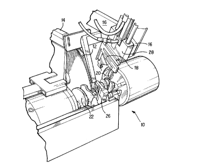
l01520253035CA 02264106 1999-02-26WO 98109771 PCT/U S97/ 15307METHOD AND APPARATUS FOR COMPUTERNTJMERICALLY CONTROLLED PIN GRINDER GAUGEBACKGROUND OF THE INVENTION1. Field of the InventionThe present invention relates to a computer numericallycontrolled (CNC) pin grinder gauging system for insuring that aplurality of crankshafts, camshafts or similar shafts andworkpieces are properly ground.2. Description of the Prior ArtThe control of the workpiece size which have beenground by grinding machines has traditionally been accomplishedby the accurate control of the axis position of the grindingwheel, an in—process gauging system or feedback from a postprocess gauge. Of these three methods, in—process gauging tocontrol the grinding wheelfeed motion has traditionally been themost accurate, since it directly measures the dimensions of theworkpiece being ground and eliminates the need for the machinecontrol to compensate for thermal changes, wheel wear, machinegeometry errors, and other process variables.U.S. Patent 4,637,144 issued to Schemel is typical ofthese in—process gauging tools. This patent monitors thediameters of crankpins during treatment in grinding machines andincludes a guide 6 having a detector 4 and two sensors 3. Thesesensors are in the form of elongated arms or fingers with edges5 which must be maintained in continuous Contact with theperipheral surface 1B of a crankpin 1 while the axis 1A orbitsor circulates along a path P. However, with the advent ofprecision grinding processes for parts which are not round, suchas cams, and for round parts which are ground while being rotatedon an axis other than their geometric center, new problems areintroduced for accurately controlling the workpiece size.The present invention.describes a process and apparatuswhich would combine the elements of post—process gauging and in—process gauging to control the workpiece size to the degreenecessary for the production of automotive crankshafts andcamshafts.10152025CA 02264106 1999-02-26wo 93/09771 PCT/US97/153072SUMMARY OF THE INVENTIONThe problems inherent in the prior art are addressedby the present invention which is directed to a CNC grindingprocess for accurately machining crankshafts having a number ofcrankpins which entails generating the crankpin geometry’ bymotion of a grinding wheel in—feed axis, while the crankshaft isbeing rotated about or near its bearing axis. In—process gaugingof the workpiece during grinding would require the gauge head tofollow the crankpin through its rotation as shown in the Schemelpatent. The present invention utilizes a gauge head mounted onthe grinding" machine which is able to measure the size ofcrankpins on the workpiece being ground at various points in themachine cycle. Movement of the grinding wheel, the rotation ofthe workpiece and the movement of the gauge head are controlledby a microprocessor provided in the machine. The micro-processor contains a memory which includes the geometry andtolerances for the various parts of the workpiece which areground. Based upon the actual measured size of at least aportion of the workpiece, the movement of the grinding wheel isautomatically controlled.These together with other objects of the invention,along with the various features of novelty which characterize theinvention, are pointed out with particularity in the claims nextto and forming a part of this disclosure. For a better under-standing of the invention, its operating advantages and thespecific objects obtained by its uses, reference should be madeto the accompanying drawings and descriptive matter in which itwas illustrated preferred embodiments of the invention. CA 02264106 1999-02-26wo 93/09771 PCTIUS97/153073BRIEF DESCRIPTION OF THE DRAWINGSFIG. 1 is a perspective drawing of a grinding machineoperating under the process of the present invention;FIGS. 2 and 3 are flow diagrams of the presentinvention; andFIG. 4 is a block diagram of the control system for thepresent invention.l01520253035CA 02264106 1999-02-26W0 98/09771 PCT/US97/153074DETAILED DESCRIPTION OF THE INVENTIONFIG. 1 illustrates a typical grinding machine 10 usedto grind a crankshaft 22 or other workpiece having a pluralityof crankpins or other grindable parts. A standard rotatinggrinding wheel 12 that can be advanced to or retracted from thecrankshaft or workpiece is utilized. Similarly, the workpieceis affixed to the grinding machine in such a manner to allow itto rotate, as well as to be advanced or retracted in the Z—axisdirection to allow various surfaces to be ground by the grindingwheel 12.workpiece in its proper position.Various clamps 24 and 26 are used to clamp theA gauge 18 is attached to a moveable support 28 whichwill allow the gauge to contact a surface, such as a crankpinwhich has been subjected to the grinding action of the grindwheel 12.connections used to move the support 28 to the crankpin.Lateral supports 14 and 16 are used to provide variousIt isnoted that the carriage traverse moves the work along the Z axisto position the portion of the workpiece to be ground in frontof the grinding wheel 12 or gauge 18. The gauge does not movealong the lateral X—axis or the vertical Y-axis. The gauge 18is provided with two moveable jaws 20 which would allow the gaugeto accurately measure the size of a particular crankpin or othermachined piece.FIG.4 illustrates a typical micro processor control 30used to control the operation of the grinding machine 10. Thiscontrol would include a controllable memory 34 such as an EPROM,EEPROM or similar memory, which would include various algorithmsfor operating the grinding machine as well as various parameterssuch as the size of each of the machined crankpins as well astolerances for each of these pins. The memory 34 is connectedto a control device 32 which would control the operation of thegauge 18, the grinding wheel 12 as well the rotation of theBased upon the sensedthe distance that thecrankshaft during the grinding operation.measurement of one or more crankpins,grinding wheel 12 would travel to grind the measured crankpin ora subsequent crankpin will be altered.101520253035CA 02264106 1999-02-26WO 98/09771 PCT/US97/153075FIGS. 2 and 3 illustrates the operation of the grindingInitially, thememory 34 provided in the microprocessor control 30 is loadedprocess according to the present invention.with the specific size of each crankpin to be machined as wellas tolerances for each of these crankpins. Furthermore, analgorithm is included in the memory 34 which would alter the in-feed distance of the grinding wheel 12 based upon measured valuesof one or more crankpins. Once this information is provided inthe memory, the grinding machine is cleared to accept a newworkpiece, such as a crankshaft having a number of crankpinswhich must be machined. A left hand pusher would be advanced tosecure the crankpin against a right—handed stop. Obviously, aright—handed pusher could be utilized which would advance againsta left—handed stop with the crankshaft therebetween. Once thecrankshaft is secured in place, an angular locator would rotatethe crankshaft so that it is in the proper location for the firstpin to be ground and subsequently measured by the gauge 18.Proximity switches are included in the grinding machine to insurethat the crankshaft is in its proper position, and whether theproper crankshaft or the workpiece has been inserted into themachine. If the crankshaft is not properly positioned, or if theimproper crankshaft has been inserted into the grinding machine,the automatic cycle of the grinding machine would be interruptedto force operator intervention. Once the problem has beenalleviated, the cycle would be reinitiated. The clamps securingthe crankshaft to the grinding machine would then close and therotation of the crankshaft would be in the torque/slave mode.At this point, the angular locator would be retracted and theproper dimension of the first crankpin would be accessed from thememory 34. The grinding wheel 12 would be moved to its properposition to grind the first crankpin and a coolant for coolingthe grinding machine would be engaged.If the grinding machine is in the cold-start mode,meaning that it has been dormant for ea period of time, thegrinding wheel will grind the crankpin to a programmed sizeslightly larger than the projected finished size of the crankpin.The grinding wheel is then retracted from its grinding position1O1520253035CA 02264106 1999-02-26wo 93/09771 PCT/US97/153076and the gauge 18 is moved into position to measure the size ofthis first crankpin. The actual size of this crankpin is thencompared to the projected size of the pin and the wheel feed issynchronized accordingly. This new wheel feed distance would beinputted into the memory 34 of the microprocessor 30 to subse-quently control the movement of the grinding wheel 12. The gauge18 is then retracted and the grinding wheel 12 is advanced togrind the first crankpin to size. The grinding wheel 12 is thenretracted and the crankshaft 22 is moved to its next position forgrinding the second crankpin. The pin adjustment data which wasobtained by comparing the projected size of the first crankpinto its measured size in the cold—start mode, would be used toadvance the grinding wheel 12 for a distance to grind the secondcrankpin to its proper size. It is noted that no measurement ofthe second crankpin is made. The grinding wheel is thenretracted and the third crankpin is moved into position to beground by the grinding wheel 12. All subsequent crankpins areground in this manner. At this point, this first crankshaft isremoved and a second crankshaft is inserted into its place andthe machining of this crankshaft is continued in the cold—startmode as outlined hereinabove. This cold—start mode wouldcontinue for a predetermined amount of time or a predeterminednumber of crankshafts, such as five. It is noted that in thecold—start mode, only the first of the crankpins of any crank-shaft is measured.Once a predetermined number of crankshafts have beenthe grindingwhen thegrinding machine is operating in the normal mode, the firstmachined, or‘ a predetermined tine has elapsed,machine will begin to operate in the normal mode.crankpin of the crankshaft would be nachined based upon themeasurement made with respect to the last measured crankpin. Inthis mode, the first crankpin of each of the crankshafts ismachined without any measurement. Once the last crankpin of thecrankshaft is machined by the grinding wheel 12 operating in thenormal mode, the size of this crankpin is measured and comparedto the projected size of that crankpin. If the measured sizeequals the projected size, the crankshaft is removed from the1015202530CA 02264106 1999-02-26W0 98,09-m PCT/US97/153077machine and a new crankshaft to be machined is inserted into thegrinding machine. If the measured size does not equal theprojected size, but is within a particular tolerance, thedistance of the grinding wheel in—feed is adjusted by a predeter-mined percentage of the size error of this pin. It is noted thatthis last measured crankpin would not be reground. However, thedistance of the grinding wheel in—feed would be changed accord-ingly.the crankpin and the actual measured size of the crankpin fallsHowever, if the difference between the projected size ofbeyond this tolerance, the grinding machine will be faulted andthe production would be stopped until a correction is made to themachine. It is noted that when the grinding machine is operatingin the normal mode, a measurement is made only to the lastcrankpin of a particular crankshaft. Alternatively, when themachine is operating in the normal mode, it might not benecessary to measure each of the last crankpins of any crankshaftif the machine is sensed to be operating ‘very close to theprojected values of the crankpins. In this instance, measure-ments could be made to every second or third or fourth crank-shaft, etc.It is important to note that the teachings of thepresent invention need not be utilized only when machining orgrinding ea workpiece have a number of successive grindablesurfaces which will be ground to the same dimension, but couldbe employed if the workpiece includes only a single surface tobe ground.It is understood that the invention is not confined tothe particular construction and arrangement herein and illustrat-ed and described but embraces such modified forms thereof as comewithin the scope of the following claims.
Representative Drawing
A single figure which represents the drawing illustrating the invention.
Administrative Status

For a clearer understanding of the status of the application/patent presented on this page, the site Disclaimer , as well as the definitions for Patent , Administrative Status , Maintenance Fee  and Payment History  should be consulted.

Administrative Status

Title Date
Forecasted Issue Date 2003-11-18
(86) PCT Filing Date 1997-09-04
(87) PCT Publication Date 1998-03-12
(85) National Entry 1999-02-26
Examination Requested 1999-02-26
(45) Issued 2003-11-18
Deemed Expired 2015-09-04

Abandonment History

There is no abandonment history.

Payment History

Fee Type Anniversary Year Due Date Amount Paid Paid Date
Request for Examination $400.00 1999-02-26
Application Fee $300.00 1999-02-26
Maintenance Fee - Application - New Act 2 1999-09-07 $100.00 1999-08-17
Registration of a document - section 124 $100.00 2000-02-25
Registration of a document - section 124 $100.00 2000-07-05
Maintenance Fee - Application - New Act 3 2000-09-05 $100.00 2000-09-01
Maintenance Fee - Application - New Act 4 2001-09-04 $100.00 2001-08-14
Maintenance Fee - Application - New Act 5 2002-09-04 $150.00 2002-08-14
Final Fee $300.00 2003-07-23
Maintenance Fee - Application - New Act 6 2003-09-04 $150.00 2003-08-25
Maintenance Fee - Patent - New Act 7 2004-09-07 $200.00 2004-08-20
Maintenance Fee - Patent - New Act 8 2005-09-06 $200.00 2005-08-19
Registration of a document - section 124 $100.00 2006-04-27
Maintenance Fee - Patent - New Act 9 2006-09-05 $200.00 2006-08-17
Maintenance Fee - Patent - New Act 10 2007-09-04 $250.00 2007-08-17
Maintenance Fee - Patent - New Act 11 2008-09-04 $250.00 2008-08-18
Maintenance Fee - Patent - New Act 12 2009-09-04 $250.00 2009-08-19
Maintenance Fee - Patent - New Act 13 2010-09-06 $250.00 2010-08-17
Maintenance Fee - Patent - New Act 14 2011-09-05 $250.00 2011-08-17
Maintenance Fee - Patent - New Act 15 2012-09-04 $450.00 2012-08-17
Maintenance Fee - Patent - New Act 16 2013-09-04 $450.00 2013-08-19
Owners on Record

Note: Records showing the ownership history in alphabetical order.

Current Owners on Record
CINETIC LANDIS GRINDING CORP.
Past Owners on Record
HYKES, TIMOTHY W.
MOWAN, RICKY L.
UNOVA INDUSTRIAL AUTOMATION SYSTEMS, INC.
UNOVA IP CORP.
Past Owners that do not appear in the "Owners on Record" listing will appear in other documentation within the application.
Documents

To view selected files, please enter reCAPTCHA code :


To view images, click a link in the Document Description column. To download the documents, select one or more checkboxes in the first column and then click the "Download Selected in PDF format (Zip Archive)" or the "Download Selected as Single PDF" button.

List of published and non-published patent-specific documents on the CPD .

If you have any difficulty accessing content, you can call the Client Service Centre at 1-866-997-1936 or send them an e-mail at CIPO Client Service Centre.


Document
Description 
Date
(yyyy-mm-dd) 
Number of pages   Size of Image (KB) 
Representative Drawing 1999-05-06 1 19
Claims 2003-01-17 10 424
Cover Page 2003-10-15 1 48
Claims 1999-02-27 10 452
Cover Page 1999-05-06 1 50
Claims 1999-02-27 11 413
Abstract 1999-02-26 1 42
Description 1999-02-26 7 321
Claims 1999-02-26 9 350
Drawings 1999-02-26 4 99
Fees 2002-08-14 1 39
Correspondence 1999-04-13 1 32
Prosecution-Amendment 1999-02-26 12 448
Prosecution-Amendment 1999-02-26 1 19
PCT 1999-02-26 5 228
Assignment 1999-02-26 3 109
PCT 1999-08-30 1 15
Assignment 2000-02-25 3 116
Correspondence 2000-04-05 2 2
Assignment 2000-07-05 5 190
PCT 1999-02-27 5 237
Assignment 2000-08-04 6 212
Prosecution-Amendment 2002-07-17 3 132
Prosecution-Amendment 2003-01-17 13 570
Correspondence 2003-07-23 1 54
Fees 2003-08-25 1 37
Fees 2000-09-01 1 35
Fees 1999-08-17 1 41
Fees 2001-08-14 1 36
Assignment 2006-04-27 9 335