Language selection

Search

Patent 2264361 Summary

Third-party information liability

Some of the information on this Web page has been provided by external sources. The Government of Canada is not responsible for the accuracy, reliability or currency of the information supplied by external sources. Users wishing to rely upon this information should consult directly with the source of the information. Content provided by external sources is not subject to official languages, privacy and accessibility requirements.

Claims and Abstract availability

Any discrepancies in the text and image of the Claims and Abstract are due to differing posting times. Text of the Claims and Abstract are posted:

  • At the time the application is open to public inspection;
  • At the time of issue of the patent (grant).
(12) Patent Application: (11) CA 2264361
(54) English Title: ECCENTRIC WORM PUMP
(54) French Title: POMPE A VIS EXCENTRIQUE
Status: Deemed Abandoned and Beyond the Period of Reinstatement - Pending Response to Notice of Disregarded Communication
Bibliographic Data
(51) International Patent Classification (IPC):
  • F04D 3/02 (2006.01)
  • F04C 2/107 (2006.01)
(72) Inventors :
  • FENTON, GORDON L. (United States of America)
(73) Owners :
  • SEEPEX SEEBERGER GMBH + CO
(71) Applicants :
  • SEEPEX SEEBERGER GMBH + CO (Germany)
(74) Agent: BORDEN LADNER GERVAIS LLP
(74) Associate agent:
(45) Issued:
(22) Filed Date: 1999-03-23
(41) Open to Public Inspection: 1999-09-28
Examination requested: 1999-07-20
Availability of licence: N/A
Dedicated to the Public: N/A
(25) Language of filing: English

Patent Cooperation Treaty (PCT): No

(30) Application Priority Data:
Application No. Country/Territory Date
198 13 999.3-15 (Germany) 1998-03-28

Abstracts

English Abstract


An eccentric worm pump has a tubular stator extending
along a main axis and having an intake side and an output side,
an eccentric worm fitting in the stator and centered on a rotor
axis offset from the main axis, an intake housing forming an
intake compartment opening into the intake side, a connecting
shaft extending along the main axis from the rotor through the
intake compartment, and a drive shaft extending along the main
axis from the connecting shaft out of the intake compartment.
The rotor, connecting shaft, and drive shaft are unitarily formed
of plastic. A seal housing mounted on the intake housing seals
around the drive shaft. A drive connected to the drive shaft
rotates the drive shaft, connecting shaft, and rotor about the
axis to draw fluid through the stator from the intake side to the
output side thereof.


Claims

Note: Claims are shown in the official language in which they were submitted.

I CLAIM:
1. An eccentric worm pump comprising:
a tubular stator extending along a main axis and having
an intake side and an output side;
an eccentric worm fitting in the stator and centered on
a rotor axis offset from the main axis;
an intake housing forming an intake compartment opening
into the intake side;
a connecting shaft extending along the main axis from
the rotor through the intake compartment;
a drive shaft extending along the main axis from the
connecting shaft out of the intake compartment, the rotor,
connecting shaft, and drive shaft being unitarily formed of
plastic;
a seal housing mounted on the intake housing and
sealing around the drive shaft; and
drive means connected to the drive shaft for rotating
the drive shaft, connecting shaft, and rotor about the axis and
thereby drawing fluid through the stator from the intake side to
the output side thereof.
-7-

2. The eccentric worm pump defined in claim 1 wherein
the unitary worm, connecting shaft, and drive shaft are formed
between the worm and the connecting shaft and between the
connecting shaft and the drive shaft with flex regions of reduced
cross section.
3. The eccentric worm pump defined in claim 2 wherein
the plastic is reinforced with glass fibers.
4. The eccentric worm pump defined in claim 2 wherein
the plastic is a polyamide.
5. The eccentric worm pump defined in claim 4 wherein
the polyamide is Nylon 66.
6. The eccentric worm pump defined in claim 1 wherein
the plastic is polytetrafluoroethylene.
7. The eccentric worm pump defined in claim 6 wherein
the plastic contains by weight 10% to 15% graphite.
-8-

8. The eccentric worm pump defined in claim 1 wherein
the connecting shaft is along its entire length of smaller cross
section than the drive shaft and the rotor, whereby the entire
connecting shaft can flex.
9. The eccentric worm pump defined in claim 1 wherein
the stator is also made of plastic.
-9-

Description

Note: Descriptions are shown in the official language in which they were submitted.

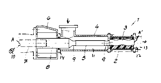
21031101520CA 02264361 1999-03-23ECCENTRIC WORM PUMPEBEQIEIQAIIQEFIELD 0! TH! INVENTIONThe present invention relates to an eccentric wormpump. More particularly this invention concerns such a pumphaving an eccentric worm rotor rotated about an axis in a statorto move a fluid axially.BACKGROUND OF THE INVENTIONAn eccentric worm pump as used for instance for pumpingmedicines, foodstuffs, dyes, and the like, typically has atubular stator extending along a main axis and having an intakeside and an output side, an eccentric worm fitting in the statorand centered on a rotor axis offset from the main axis, an intakehousing forming an intake compartment opening into the intakeside, and a connecting shaft extending along the main axis fromthe rotor through the intake compartment. A drive shaft extendsalong the main axis from the connecting shaft out of the intakecompartment through a seal housing mounted on the intake housingand sealing around the drive shaft. A drive motor connected tothe drive shaft rotates the drive shaft, connecting shaft, and21031101520CA 02264361 1999-03-23rotor about the axis to draw fluid through the stator from theintake side to the output side thereof.As the worm, which typically is formed with a roundedhelicoidal ridge that fits with a complementary inwardly opengroove of the stator, is centered on an axis offset from the mainaxis, it must in effect orbit about the main axis as it isrotated. Thus it is necessary to provide a universal or cardanjoint at each end of the connecting shaft, connected on thedownstream side to the rotor and on the upstream side to thedrive shaft, to allow such movement of these parts which are alltypically made of steel. These joints must be protected byflexible cuffs.As a result such a pump is a very complex and expensivepiece of equipment. While first costs are very high, when one ofthe couplings or its cuffs fails, repair costs are also quiteelevated.OBJSCTS OF THE INVENTIONIt is therefore an object of the present invention toprovide an improved eccentric worm pump.Another object is the provision of such an improvedeccentric worm pump which overcomes the above-given disadvan-tages, that is which is of simple and inexpensive construction,but that is as effective and durable as the prior-art such pumps.2103110152025CA 02264361 1999-03-23SUMMARY OF THE INVENTIONAn eccentric worm pump has according to the invention atubular stator extending along a main axis and having an intakeside and an output side, an eccentric worm fitting in the statorand centered on a rotor axis offset from the main axis, an intakehousing forming an intake compartment opening into the intakeside, a connecting shaft extending along the main axis from therotor through the intake compartment, and a drive shaft extendingalong the main axis from the connecting shaft out of the intakecompartment. The rotor, connecting shaft, and drive shaft areunitarily formed of plastic. A seal housing mounted on theintake housing seals around the drive shaft. A drive connectedto the drive shaft rotates the drive shaft, connecting shaft, androtor about the axis to draw fluid through the stator from theintake side to the output side thereof. According to the inven-tion the unitary worm, connecting shaft, and drive shaft areformed between the worm and the connecting shaft and between theconnecting shaft and the drive shaft with flex regions of reducedcross section.This arrangement therefore completely eliminates theneed for complex joints between the ends of the connecting shaftand the rotor and drive shaft. Instead the one-piece assemblycan flex along the connecting shaft, which according to theinvention is along its entire length of smaller cross sectionthan the drive shaft and the rotor so that the entire connecting210311015CA 02264361 1999-03-23shaft can flex, or the assembly can bend at the regions ofreduced cross-sectional size. Such a pump is extremely easy tomaintain aseptic for use in the food and medicine industries. Itcan nonetheless produce relatively high pressures, as much as24 bar. In addition the rotor according to the invention can besubstituted in an existing pump in place of the prior-art assem-bly comprising three different parts interconnected by twocouplings.In accordance with the invention the stator also can bemade of plastic, preferably an elastomer. Thus the pump will beextremely simple and easy to clean.The plastic according to the invention is reinforcedwith glass fibers. It can be a polyamide, preferably Nylon 66.This synthetic resin is very durable and does not absorb aro-matics, so it is ideal when the pump is used for conveyingsolvent-containing substances. Alternately the plastic can bepolytetrafluoroethylene, preferably containing by weight 10% to15% graphite. This resin is known for its low friction and self-lubricating properties.CA 02264361 1999-03-2321031101520BRIEF DESCRIPTION OF THE DRAWINGThe above and other objects, features, and advantageswill become more readily apparent from the following description,reference being made to the accompanying drawing in which:FIG. 1 is a small-scale partly diagrammatic axialsection through the pump according to the invention; andFIG. 2 is a partly sectional side view of the pumprotor.SPECIFIC DESCRIPTIONAs seen in FIG. 1 an eccentric worm pump 1 has a statorcentered on a horizontal axis A and surrounding an eccentric worm3 centered on an axis A’ offset slightly from but parallel to theaxis A. Rotation of the rotor 3 about the axis A will causefluid to be sucked left to right as seen in the drawing from anintake compartment 11 formed by an intake housing 4 to an outletcompartment 12 formed by an outlet housing 13. This is generallystandard construction.As also shown in FIG. 2 the rotor 3 is unitarily formedwith a small-diameter cylindrical connecting shaft 5 that extendsthrough the intake compartment 11 and that is joined in turn to alarge-diameter cylindrical drive shaft 8 projecting out of theintake compartment 11 through a seal 14 into a seal compartmentwhere it is joined to an output shaft 7 of a drive motor 10. The2103110CA 02264361 1999-03-23shaft 8 is centered on the axis A. The rotor 3, connecting shaft5, and drive shaft 8 are all unitarily formed of a syntheticresin, here a polyamide, Nylon 66 that is reinforced with glassfibers, or polytetrafluoroethylene with 10% to 15% graphite. Itis formed between the rotor 2 and connecting shaft 5 and betweenthis connecting shaft 5 and drive shaft 8 with regions 9 ofreduced diameter formed as outwardly open circular-sectionannular grooves that impart some flexibility to the one-pieceassembly 3, 5, 8 at these regions 9.The stator 2 is also according to the invention formedof a synthetic resin, preferably one that is somewhat elastomericso it can fit tightly to the worm 3 where needed.
Representative Drawing
A single figure which represents the drawing illustrating the invention.
Administrative Status

2024-08-01:As part of the Next Generation Patents (NGP) transition, the Canadian Patents Database (CPD) now contains a more detailed Event History, which replicates the Event Log of our new back-office solution.

Please note that "Inactive:" events refers to events no longer in use in our new back-office solution.

For a clearer understanding of the status of the application/patent presented on this page, the site Disclaimer , as well as the definitions for Patent , Event History , Maintenance Fee  and Payment History  should be consulted.

Event History

Description Date
Inactive: IPC from MCD 2006-03-12
Application Not Reinstated by Deadline 2004-03-23
Time Limit for Reversal Expired 2004-03-23
Deemed Abandoned - Failure to Respond to Maintenance Fee Notice 2003-03-24
Inactive: Abandoned - No reply to s.30(2) Rules requisition 2003-03-20
Inactive: Single transfer 2003-02-24
Inactive: S.30(2) Rules - Examiner requisition 2002-09-20
Amendment Received - Voluntary Amendment 2002-04-12
Inactive: S.30(2) Rules - Examiner requisition 2001-10-24
Application Published (Open to Public Inspection) 1999-09-28
Inactive: Cover page published 1999-09-27
Letter Sent 1999-08-05
Request for Examination Received 1999-07-20
Request for Examination Requirements Determined Compliant 1999-07-20
All Requirements for Examination Determined Compliant 1999-07-20
Letter Sent 1999-05-12
Inactive: First IPC assigned 1999-05-05
Inactive: IPC assigned 1999-05-05
Inactive: Single transfer 1999-04-22
Inactive: Applicant deleted 1999-04-07
Filing Requirements Determined Compliant 1999-04-07
Inactive: Courtesy letter - Evidence 1999-04-07
Inactive: Filing certificate - No RFE (English) 1999-04-07
Application Received - Regular National 1999-04-07

Abandonment History

Abandonment Date Reason Reinstatement Date
2003-03-24

Maintenance Fee

The last payment was received on 2002-01-18

Note : If the full payment has not been received on or before the date indicated, a further fee may be required which may be one of the following

  • the reinstatement fee;
  • the late payment fee; or
  • additional fee to reverse deemed expiry.

Please refer to the CIPO Patent Fees web page to see all current fee amounts.

Fee History

Fee Type Anniversary Year Due Date Paid Date
Registration of a document 1999-03-23
Application fee - standard 1999-03-23
Request for examination - standard 1999-07-20
MF (application, 2nd anniv.) - standard 02 2001-03-23 2000-12-15
MF (application, 3rd anniv.) - standard 03 2002-03-25 2002-01-18
Owners on Record

Note: Records showing the ownership history in alphabetical order.

Current Owners on Record
SEEPEX SEEBERGER GMBH + CO
Past Owners on Record
GORDON L. FENTON
Past Owners that do not appear in the "Owners on Record" listing will appear in other documentation within the application.
Documents

To view selected files, please enter reCAPTCHA code :


To view images, click a link in the Document Description column. To download the documents, select one or more checkboxes in the first column and then click the "Download Selected in PDF format (Zip Archive)" or the "Download Selected as Single PDF" button.

List of published and non-published patent-specific documents on the CPD .

If you have any difficulty accessing content, you can call the Client Service Centre at 1-866-997-1936 or send them an e-mail at CIPO Client Service Centre.


Document
Description 
Date
(yyyy-mm-dd) 
Number of pages   Size of Image (KB) 
Representative drawing 1999-09-13 1 8
Description 1999-03-23 6 188
Abstract 1999-03-23 1 25
Claims 1999-03-23 3 57
Drawings 1999-03-23 1 17
Cover Page 1999-09-13 1 35
Claims 2002-04-12 2 63
Filing Certificate (English) 1999-04-07 1 165
Courtesy - Certificate of registration (related document(s)) 1999-05-12 1 116
Acknowledgement of Request for Examination 1999-08-05 1 193
Reminder of maintenance fee due 2000-11-27 1 112
Courtesy - Abandonment Letter (Maintenance Fee) 2003-04-22 1 176
Courtesy - Abandonment Letter (R30(2)) 2003-05-29 1 167
Correspondence 1999-04-08 1 30