Sélection de la langue

Search

Sommaire du brevet 2264361 

Énoncé de désistement de responsabilité concernant l'information provenant de tiers

Une partie des informations de ce site Web a été fournie par des sources externes. Le gouvernement du Canada n'assume aucune responsabilité concernant la précision, l'actualité ou la fiabilité des informations fournies par les sources externes. Les utilisateurs qui désirent employer cette information devraient consulter directement la source des informations. Le contenu fourni par les sources externes n'est pas assujetti aux exigences sur les langues officielles, la protection des renseignements personnels et l'accessibilité.

Disponibilité de l'Abrégé et des Revendications

L'apparition de différences dans le texte et l'image des Revendications et de l'Abrégé dépend du moment auquel le document est publié. Les textes des Revendications et de l'Abrégé sont affichés :

  • lorsque la demande peut être examinée par le public;
  • lorsque le brevet est émis (délivrance).
(12) Demande de brevet: (11) CA 2264361
(54) Titre français: POMPE A VIS EXCENTRIQUE
(54) Titre anglais: ECCENTRIC WORM PUMP
Statut: Réputée abandonnée et au-delà du délai pour le rétablissement - en attente de la réponse à l’avis de communication rejetée
Données bibliographiques
(51) Classification internationale des brevets (CIB):
  • F04D 3/02 (2006.01)
  • F04C 2/107 (2006.01)
(72) Inventeurs :
  • FENTON, GORDON L. (Etats-Unis d'Amérique)
(73) Titulaires :
  • SEEPEX SEEBERGER GMBH + CO
(71) Demandeurs :
  • SEEPEX SEEBERGER GMBH + CO (Allemagne)
(74) Agent: BORDEN LADNER GERVAIS LLP
(74) Co-agent:
(45) Délivré:
(22) Date de dépôt: 1999-03-23
(41) Mise à la disponibilité du public: 1999-09-28
Requête d'examen: 1999-07-20
Licence disponible: S.O.
Cédé au domaine public: S.O.
(25) Langue des documents déposés: Anglais

Traité de coopération en matière de brevets (PCT): Non

(30) Données de priorité de la demande:
Numéro de la demande Pays / territoire Date
198 13 999.3-15 (Allemagne) 1998-03-28

Abrégés

Abrégé anglais


An eccentric worm pump has a tubular stator extending
along a main axis and having an intake side and an output side,
an eccentric worm fitting in the stator and centered on a rotor
axis offset from the main axis, an intake housing forming an
intake compartment opening into the intake side, a connecting
shaft extending along the main axis from the rotor through the
intake compartment, and a drive shaft extending along the main
axis from the connecting shaft out of the intake compartment.
The rotor, connecting shaft, and drive shaft are unitarily formed
of plastic. A seal housing mounted on the intake housing seals
around the drive shaft. A drive connected to the drive shaft
rotates the drive shaft, connecting shaft, and rotor about the
axis to draw fluid through the stator from the intake side to the
output side thereof.

Revendications

Note : Les revendications sont présentées dans la langue officielle dans laquelle elles ont été soumises.


I CLAIM:
1. An eccentric worm pump comprising:
a tubular stator extending along a main axis and having
an intake side and an output side;
an eccentric worm fitting in the stator and centered on
a rotor axis offset from the main axis;
an intake housing forming an intake compartment opening
into the intake side;
a connecting shaft extending along the main axis from
the rotor through the intake compartment;
a drive shaft extending along the main axis from the
connecting shaft out of the intake compartment, the rotor,
connecting shaft, and drive shaft being unitarily formed of
plastic;
a seal housing mounted on the intake housing and
sealing around the drive shaft; and
drive means connected to the drive shaft for rotating
the drive shaft, connecting shaft, and rotor about the axis and
thereby drawing fluid through the stator from the intake side to
the output side thereof.
-7-

2. The eccentric worm pump defined in claim 1 wherein
the unitary worm, connecting shaft, and drive shaft are formed
between the worm and the connecting shaft and between the
connecting shaft and the drive shaft with flex regions of reduced
cross section.
3. The eccentric worm pump defined in claim 2 wherein
the plastic is reinforced with glass fibers.
4. The eccentric worm pump defined in claim 2 wherein
the plastic is a polyamide.
5. The eccentric worm pump defined in claim 4 wherein
the polyamide is Nylon 66.
6. The eccentric worm pump defined in claim 1 wherein
the plastic is polytetrafluoroethylene.
7. The eccentric worm pump defined in claim 6 wherein
the plastic contains by weight 10% to 15% graphite.
-8-

8. The eccentric worm pump defined in claim 1 wherein
the connecting shaft is along its entire length of smaller cross
section than the drive shaft and the rotor, whereby the entire
connecting shaft can flex.
9. The eccentric worm pump defined in claim 1 wherein
the stator is also made of plastic.
-9-

Description

Note : Les descriptions sont présentées dans la langue officielle dans laquelle elles ont été soumises.
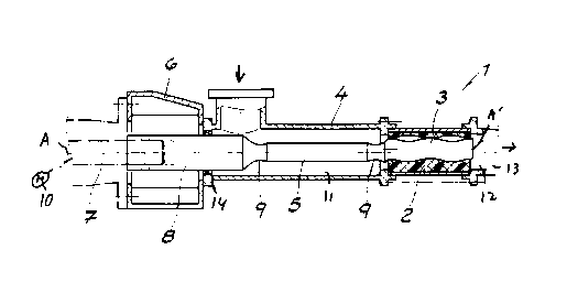
21031101520CA 02264361 1999-03-23ECCENTRIC WORM PUMPEBEQIEIQAIIQEFIELD 0! TH! INVENTIONThe present invention relates to an eccentric wormpump. More particularly this invention concerns such a pumphaving an eccentric worm rotor rotated about an axis in a statorto move a fluid axially.BACKGROUND OF THE INVENTIONAn eccentric worm pump as used for instance for pumpingmedicines, foodstuffs, dyes, and the like, typically has atubular stator extending along a main axis and having an intakeside and an output side, an eccentric worm fitting in the statorand centered on a rotor axis offset from the main axis, an intakehousing forming an intake compartment opening into the intakeside, and a connecting shaft extending along the main axis fromthe rotor through the intake compartment. A drive shaft extendsalong the main axis from the connecting shaft out of the intakecompartment through a seal housing mounted on the intake housingand sealing around the drive shaft. A drive motor connected tothe drive shaft rotates the drive shaft, connecting shaft, and21031101520CA 02264361 1999-03-23rotor about the axis to draw fluid through the stator from theintake side to the output side thereof.As the worm, which typically is formed with a roundedhelicoidal ridge that fits with a complementary inwardly opengroove of the stator, is centered on an axis offset from the mainaxis, it must in effect orbit about the main axis as it isrotated. Thus it is necessary to provide a universal or cardanjoint at each end of the connecting shaft, connected on thedownstream side to the rotor and on the upstream side to thedrive shaft, to allow such movement of these parts which are alltypically made of steel. These joints must be protected byflexible cuffs.As a result such a pump is a very complex and expensivepiece of equipment. While first costs are very high, when one ofthe couplings or its cuffs fails, repair costs are also quiteelevated.OBJSCTS OF THE INVENTIONIt is therefore an object of the present invention toprovide an improved eccentric worm pump.Another object is the provision of such an improvedeccentric worm pump which overcomes the above-given disadvan-tages, that is which is of simple and inexpensive construction,but that is as effective and durable as the prior-art such pumps.2103110152025CA 02264361 1999-03-23SUMMARY OF THE INVENTIONAn eccentric worm pump has according to the invention atubular stator extending along a main axis and having an intakeside and an output side, an eccentric worm fitting in the statorand centered on a rotor axis offset from the main axis, an intakehousing forming an intake compartment opening into the intakeside, a connecting shaft extending along the main axis from therotor through the intake compartment, and a drive shaft extendingalong the main axis from the connecting shaft out of the intakecompartment. The rotor, connecting shaft, and drive shaft areunitarily formed of plastic. A seal housing mounted on theintake housing seals around the drive shaft. A drive connectedto the drive shaft rotates the drive shaft, connecting shaft, androtor about the axis to draw fluid through the stator from theintake side to the output side thereof. According to the inven-tion the unitary worm, connecting shaft, and drive shaft areformed between the worm and the connecting shaft and between theconnecting shaft and the drive shaft with flex regions of reducedcross section.This arrangement therefore completely eliminates theneed for complex joints between the ends of the connecting shaftand the rotor and drive shaft. Instead the one-piece assemblycan flex along the connecting shaft, which according to theinvention is along its entire length of smaller cross sectionthan the drive shaft and the rotor so that the entire connecting210311015CA 02264361 1999-03-23shaft can flex, or the assembly can bend at the regions ofreduced cross-sectional size. Such a pump is extremely easy tomaintain aseptic for use in the food and medicine industries. Itcan nonetheless produce relatively high pressures, as much as24 bar. In addition the rotor according to the invention can besubstituted in an existing pump in place of the prior-art assem-bly comprising three different parts interconnected by twocouplings.In accordance with the invention the stator also can bemade of plastic, preferably an elastomer. Thus the pump will beextremely simple and easy to clean.The plastic according to the invention is reinforcedwith glass fibers. It can be a polyamide, preferably Nylon 66.This synthetic resin is very durable and does not absorb aro-matics, so it is ideal when the pump is used for conveyingsolvent-containing substances. Alternately the plastic can bepolytetrafluoroethylene, preferably containing by weight 10% to15% graphite. This resin is known for its low friction and self-lubricating properties.CA 02264361 1999-03-2321031101520BRIEF DESCRIPTION OF THE DRAWINGThe above and other objects, features, and advantageswill become more readily apparent from the following description,reference being made to the accompanying drawing in which:FIG. 1 is a small-scale partly diagrammatic axialsection through the pump according to the invention; andFIG. 2 is a partly sectional side view of the pumprotor.SPECIFIC DESCRIPTIONAs seen in FIG. 1 an eccentric worm pump 1 has a statorcentered on a horizontal axis A and surrounding an eccentric worm3 centered on an axis A’ offset slightly from but parallel to theaxis A. Rotation of the rotor 3 about the axis A will causefluid to be sucked left to right as seen in the drawing from anintake compartment 11 formed by an intake housing 4 to an outletcompartment 12 formed by an outlet housing 13. This is generallystandard construction.As also shown in FIG. 2 the rotor 3 is unitarily formedwith a small-diameter cylindrical connecting shaft 5 that extendsthrough the intake compartment 11 and that is joined in turn to alarge-diameter cylindrical drive shaft 8 projecting out of theintake compartment 11 through a seal 14 into a seal compartmentwhere it is joined to an output shaft 7 of a drive motor 10. The2103110CA 02264361 1999-03-23shaft 8 is centered on the axis A. The rotor 3, connecting shaft5, and drive shaft 8 are all unitarily formed of a syntheticresin, here a polyamide, Nylon 66 that is reinforced with glassfibers, or polytetrafluoroethylene with 10% to 15% graphite. Itis formed between the rotor 2 and connecting shaft 5 and betweenthis connecting shaft 5 and drive shaft 8 with regions 9 ofreduced diameter formed as outwardly open circular-sectionannular grooves that impart some flexibility to the one-pieceassembly 3, 5, 8 at these regions 9.The stator 2 is also according to the invention formedof a synthetic resin, preferably one that is somewhat elastomericso it can fit tightly to the worm 3 where needed.
Dessin représentatif
Une figure unique qui représente un dessin illustrant l'invention.
États administratifs

2024-08-01 : Dans le cadre de la transition vers les Brevets de nouvelle génération (BNG), la base de données sur les brevets canadiens (BDBC) contient désormais un Historique d'événement plus détaillé, qui reproduit le Journal des événements de notre nouvelle solution interne.

Veuillez noter que les événements débutant par « Inactive : » se réfèrent à des événements qui ne sont plus utilisés dans notre nouvelle solution interne.

Pour une meilleure compréhension de l'état de la demande ou brevet qui figure sur cette page, la rubrique Mise en garde , et les descriptions de Brevet , Historique d'événement , Taxes périodiques et Historique des paiements devraient être consultées.

Historique d'événement

Description Date
Inactive : CIB de MCD 2006-03-12
Demande non rétablie avant l'échéance 2004-03-23
Le délai pour l'annulation est expiré 2004-03-23
Réputée abandonnée - omission de répondre à un avis sur les taxes pour le maintien en état 2003-03-24
Inactive : Abandon. - Aucune rép dem par.30(2) Règles 2003-03-20
Inactive : Transfert individuel 2003-02-24
Inactive : Dem. de l'examinateur par.30(2) Règles 2002-09-20
Modification reçue - modification volontaire 2002-04-12
Inactive : Dem. de l'examinateur par.30(2) Règles 2001-10-24
Demande publiée (accessible au public) 1999-09-28
Inactive : Page couverture publiée 1999-09-27
Lettre envoyée 1999-08-05
Requête d'examen reçue 1999-07-20
Exigences pour une requête d'examen - jugée conforme 1999-07-20
Toutes les exigences pour l'examen - jugée conforme 1999-07-20
Lettre envoyée 1999-05-12
Inactive : CIB en 1re position 1999-05-05
Inactive : CIB attribuée 1999-05-05
Inactive : Transfert individuel 1999-04-22
Inactive : Demandeur supprimé 1999-04-07
Exigences de dépôt - jugé conforme 1999-04-07
Inactive : Lettre de courtoisie - Preuve 1999-04-07
Inactive : Certificat de dépôt - Sans RE (Anglais) 1999-04-07
Demande reçue - nationale ordinaire 1999-04-07

Historique d'abandonnement

Date d'abandonnement Raison Date de rétablissement
2003-03-24

Taxes périodiques

Le dernier paiement a été reçu le 2002-01-18

Avis : Si le paiement en totalité n'a pas été reçu au plus tard à la date indiquée, une taxe supplémentaire peut être imposée, soit une des taxes suivantes :

  • taxe de rétablissement ;
  • taxe pour paiement en souffrance ; ou
  • taxe additionnelle pour le renversement d'une péremption réputée.

Veuillez vous référer à la page web des taxes sur les brevets de l'OPIC pour voir tous les montants actuels des taxes.

Historique des taxes

Type de taxes Anniversaire Échéance Date payée
Enregistrement d'un document 1999-03-23
Taxe pour le dépôt - générale 1999-03-23
Requête d'examen - générale 1999-07-20
TM (demande, 2e anniv.) - générale 02 2001-03-23 2000-12-15
TM (demande, 3e anniv.) - générale 03 2002-03-25 2002-01-18
Titulaires au dossier

Les titulaires actuels et antérieures au dossier sont affichés en ordre alphabétique.

Titulaires actuels au dossier
SEEPEX SEEBERGER GMBH + CO
Titulaires antérieures au dossier
GORDON L. FENTON
Les propriétaires antérieurs qui ne figurent pas dans la liste des « Propriétaires au dossier » apparaîtront dans d'autres documents au dossier.
Documents

Pour visionner les fichiers sélectionnés, entrer le code reCAPTCHA :


Pour visualiser une image, cliquer sur un lien dans la colonne description du document. Pour télécharger l'image (les images), cliquer l'une ou plusieurs cases à cocher dans la première colonne et ensuite cliquer sur le bouton "Télécharger sélection en format PDF (archive Zip)" ou le bouton "Télécharger sélection (en un fichier PDF fusionné)".

Liste des documents de brevet publiés et non publiés sur la BDBC .

Si vous avez des difficultés à accéder au contenu, veuillez communiquer avec le Centre de services à la clientèle au 1-866-997-1936, ou envoyer un courriel au Centre de service à la clientèle de l'OPIC.


Description du
Document 
Date
(aaaa-mm-jj) 
Nombre de pages   Taille de l'image (Ko) 
Dessin représentatif 1999-09-13 1 8
Description 1999-03-23 6 188
Abrégé 1999-03-23 1 25
Revendications 1999-03-23 3 57
Dessins 1999-03-23 1 17
Page couverture 1999-09-13 1 35
Revendications 2002-04-12 2 63
Certificat de dépôt (anglais) 1999-04-07 1 165
Courtoisie - Certificat d'enregistrement (document(s) connexe(s)) 1999-05-12 1 116
Accusé de réception de la requête d'examen 1999-08-05 1 193
Rappel de taxe de maintien due 2000-11-27 1 112
Courtoisie - Lettre d'abandon (taxe de maintien en état) 2003-04-22 1 176
Courtoisie - Lettre d'abandon (R30(2)) 2003-05-29 1 167
Correspondance 1999-04-08 1 30