Note: Descriptions are shown in the official language in which they were submitted.
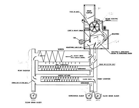
101520CA 02264373 1999-03-03GRAIN CLEANERField of the InventionThis invention is directed to a grain cleaner for use in cleaning grain and, in particular,a grain cleaning machine which is useful for farm environments.Background of the InventionGrain cleaning machines are well known. They are useful for cleaning contaminants,such as grasses, stems and weed seeds, from valuable grain. While many graincleaning machines are known, few grain cleaners are known which are particularlyuseful for farmers to use and maintain themselves. There are also few grain cleanerswhich easily convertible to clean different forms of grain and different quantities of grain.Summarv of the InventionA grain cleaner has been invented which includes features which facilitate maintenanceand repair and permit such maintenance and repair without requiring special equipment.In addition, the grain cleaner is easily convertible for use to clean a variety of graintypes (ie. peas, wheat and canola) and, in one embodiment, can handle large volumethroughput.In accordance with a broad aspect of the present invention, there is provided a graincleaner comprising a framework, a grain inlet for accepting a flow of grain, graincleaning means to separate the grain from at least some of its contaminants and a grainoutlet to conduct the grain away from the grain cleaning means, an auger flight being10152025CA 02264373 1999-03-03-2-disposed in the grain outlet, the auger ï¬ight including a trough and an auger, the troughbeing mounted to permit at least a portion of the trough to be pivoted away from theaugerIn accordance with a broad aspect of the present invention, there is provided a graincleaner comprising a framework, a grain inlet, a screen separator drum having a longaxis and supported by the framework to be rotatable about its long axis, a chuteextending to conduct materials from the screen separator drum to an indent cylinderassembly, the indent cylinder assembly having a long axis and including an indentcylinder and an auger ï¬ight extending therethrough, the indent cylinder and the augerï¬ight being supported by the framework and the indent cylinder being rotatable aboutthe long axis of the assembly and a grain outlet to conduct materials away from theauger flight, a second auger flight being disposed in the grain outlet, the auger ï¬ightincluding a trough and an auger, the trough being mounted to permit at least a portionof the trough to be pivoted away from the auger to provide access to the trough belowthe auger.In one embodiment, there is an auger ï¬ight under the separator screen. Preferably thisauger flight includes a trough with a drop away bottom for easy cleaning.Further chutes can be provided for conveying materials from other parts of the graincleaner. Preferably, the outlet of each chute is provided with an auger flight forcontrolled conveyance of the materials from the grain cleaner. Preferred auger flightshave drop away bottoms to facilitate cleaning.In accordance with another broad aspect of the present invention, there is provided agrain cleaner comprising a framework, a grain inlet for accepting a flow of grain, graincleaning means to separate the grain from at least some of its contaminants and a grainoutlet to conduct the grain away from the grain cleaning means, the grain cleaningmeans including at least one indent cylinder assembly, the indent cylinder assembly10152025CA 02264373 1999-03-03-3-including an indent cylinder having an inner surface formed with a plurality ofindentations formed thereon, the indent cylinder being formed of a sheet of materialwrapped and releasably secured into a cylindrical form and mounted about an innerframe.In one embodiment, the indent cylinder includes an outer sheet material and an innerperforated liner, the outer sheet material including a releasable locking means alignedalong two opposite edges thereof for securing the outer sheet material into thecylindrical form.To enhance the wear characteristics of the cylinder and to reduce the weight of thecylinder, the inner perforated liner is preferably formed of polymeric material.The inner perforated liner can be secured to the outer sheet, if desired. Preferably, theinner liner is secured to the outer sheet in such a way that it is removable therefrom forease of replacement. In one embodiment, the inner liner is secured to the outer sheetmaterial along an edge adjacent one of the opposite edges accommodating the lockingmeans.In accordance with a broad aspect of the present invention, there is provided a graincleaner comprising a main framework, a grain inlet for accepting a flow of grain, graincleaning means to separate the grain from at least some of its contaminants mountedon a grain cleaning means support frame and a grain outlet to conduct the grain awayfrom the grain cleaning means, the grain cleaning means support frame being moveablymounted to the main framework such that the grain cleaning means can be moveablefrom one position to another on the main framework of the grain cleaner.In one embodiment, the grain cleaner includes a second grain cleaning means mountedon a second grain cleaning means support frame, the second grain cleaning means andthe first grain cleaning means being positioned in side by side relation the grain10152025CA 02264373 1999-03-03-4-cleaning means having inside components positioned adjacent the second graincleaning means. The grain cleaning means support frame being moveably mountedon the main framework such that it can be moved outwardly from the second graincleaning means to provide access to the inside components.The grain cleaning means can be moveably mounted to the main framework in anysuitable way such as for example on rollers, rails or pivotal connections. The secondgrain cleaning means can also be made moveable over the main framework, asdesired.In accordance with another aspect of the present invention, there is provided a graincleaner comprising a framework, a grain inlet for accepting a flow of grain, graincleaning means to separate the grain from at least some of its contaminants and a grainoutlet to conduct the grain away from the grain cleaning means, the grain cleaningmeans including an air separator box including a grain inlet for permitting a ï¬ow of graininto the air separator box, a grain outlet positioned below the grain inlet such that grainpassing from the grain inlet can drop, by gravity, into the grain outlet, a means forgenerating a ï¬ow of air and directing it at the flow of grain between the grain inlet andthe grain outlet, a waste material outlet from the air box and a bafï¬e positioned betweenthe grain outlet and the waste material outlet.in one embodiment, the air separator box includes a housing formed to substantiallyprevent the ï¬ow of air from exiting the air box except through the waste material outlet.The air box can include a curved wall positioned opposite the fan. The wall is curvedto direct the flow of air toward the waste material outlet. Preferably, the height or,stated another way, the degree of extension of the baffle into the air separation box isadjustable.In accordance with another aspect of the present invention, there is provided a graincleaner comprising a framework, a grain inlet for accepting a ï¬ow of grain, grain10152025CA 02264373 1999-03-03-5-cleaning means to separate the grain from at least some of its contaminants and a grainoutlet to conduct the grain away from the grain cleaning means, the grain cleaningmeans including a scalper having a tube with openings disposed through its side walland being rotatable along the long axis thereof, a means for directing grain against thetube's outer surface to be held in position against the outer surface until the grainpasses through the openings of the side wall.The openings through the tube are selected to permit the passage therethrough of thegrain while excluding materials of size larger than the diameter of the openings.The grain cleaners of the present invention are preferably mounted on transportationmeans such as trailers for transport and use in the ï¬eld during harvest.The grain cleaning means of the present grain cleaners can be any suitable means forcleaning grain such as, for example, one or more indent cylinders and/or one or morerotary screen drums. Preferably, the grain cleaning means of the grain cleaner arepositioned within a housing. Portions of the housing are removable to permit accessto the grain cleaning means.Brief Description of the DrawingsA further, detailed, description of the invention, briefly described above, will follow byreference to the following drawings of specific embodiments of the invention. Thesedrawings depict only typical embodiments of the invention and are therefore not to beconsidered limiting of its scope. In the drawings:Figure 1 is a perspective view of a grain cleaner according to the present invention;Figure 2 is a sectional view of the grain cleaner taken along line 2-2 of Figure 1, exceptthat a portion of the rotary screen is not shown in section to show its outer surface;101520CA 02264373 1999-03-03-5-Figure 3 is a sectional view along line 3-3 of Figure 1;Figure 4 is an enlarged view of an indent cylinder wall;Figure 5A is a front elevation view of an indent cylinder useful in the present invention;Figure 5B is a sectional view along line 5B-5B of Figure 5A;Figure 5C is an enlarged view of a wall of the indent cylinder of Figure 5A;Figure 6A is an end view of a auger flight useful in the present invention;Figure 6B is a front elevation view of the auger flight of Figure 6A; andFigure 7 is an exploded perspective view of a grain cleaner frame useful in the graincleaner of the present invention;Figure 8A is a sectional view through another grain cleaner according to the presentinvention;Figure 8B is an enlarged sectional view of a scalping unit and air box useful in thepresent invention.Detailed Description of the Present InventionReferring to Figures 1, 2 and 3, the grain cleaner includes a main framework 10surrounded by a housing 12. Housing 12 includes side panels 13a, a pair of uppertarps 13b (shown partially retracted from their covering position over the grain cleanercomponents) and various other panels. Panels can be made of any suitable materialssuch as metal plates, polymeric materials (i.e. Plexiglas) or tarp fabric. A hopper 14 isprovided as a grain inlet through which a flow of grain can enter the grain cleaner. The1015202530CA 02264373 1999-03-03-7-grain cleaner is mounted on a trailer chassis 15a including wheels 15b and a hitch 15cfor towing behind a farm vehicle (not shown).The grain cleaner includes two grain separation modules 16a, 16b. More modules canbe added, or one of the two modules can be removed, as desired, for the applicationfor which it is to be used. While modules are illustrated including multiple grain cleaningmeans, modules can be provided which include fewer or more cleaning components.Hopper 14 preferably includes a grain spreading means such as a deflection bar 17.Below deflection bar 17 is a gate 18 which is rotatable by means of a handle (notshown) extending outside of the hopper. Gate 18 further deflects the grain so that itsflow is optimized for separation by means of a fan 19. In particular, gate 18 acts toseparate the flow of grain into a thin curtain. Fan 19 directs a flow of air toward thecurtain of grain moving through gate 18. The direction of the output of air from fan 19is adjustable by rotation of shroud 20. Shroud 20 can be rotated by actuation of ahandle (not shown) extending through the hopper wall. The fan's air flow acts toseparate lighter materials, such as dust and weed seeds, from the desired grain. Theremoval of lighter material can be optimized by rotating gate 18 to control the amountof grain and the thickness of the curtain of grain passing through the gate and shroud20 to control the direction of the air impinging on the grain. The speed of fan can alsobe adjusted to optimize separation. To facilitate the adjustment of gate 18 and shield20, a wall of the hopper, for example hopper front wall 14a is formed of a translucentmaterial such as polymeric glass. Preferably, the fan is elongate to act along the fulllength of the hopper and, thereby, to act on the full length of the grain curtain. In apreferred embodiment, the hopper is just over 8' wide and an 8' fan (length) is fittherein.A wall 21 extends into the hopper 14 and separates a grain chute 22 from a wastematerial chute 24. The grain chute 22 feeds into the two modules. Chute 22 can bedivided and gated, as desired, to properly direct grain into any number of modules.Each module includes a pair of rotary screens 25 (only one rotary screen can be seenin Figure 2, as one screen is disposed behind the other). The rotary screens are10152025CA 02264373 1999-03-03-3-disposed to rotate, as will be described in more detail hereinafter, about an axial shaft25'. Each rotary screen includes an outer perforated tube 26 and an agitation spiral 28mounted therein. Agitation spiral 28 need only be used if desired. However, the useof agitating spiral has been found to enhance the capacity and cleaning ability of thescreens. The agitation spiral 28 includes an upstanding wall 29 arranged in a spiralfashion from the input end of the rotary screen to the output end of the rotary screen.Wall 29 is fixed to shaft 25' and is driven to rotate therewith. Extending substantiallyparallel to the shaft 25' of the screen tumbler are intermediate walls 30 connectedbetween adjacent spiralling portions of upstanding wall 29. Outer perforated tube 26is mounted about the agitation spiral and rotates with it.As is known, rotary screens are primarily used to separate materials on the basis ofsize. Thus, in a preferred embodiment the screen is selected such that the perforationsin the outer perforated tube 26 are of a size to prevent the desired grain from passingtherethrough, while materials which are smaller than the desired grain size can passthrough the perforations. The desired grain will be maintained in the rotary screen andwill move therealong by action of the agitation spiral and/or by tilting of the screentoward the output end. Each rotary screen opens into a chute 31 at its output end.To enhance the usefulness of the grain cleaner, the perforation size of the rotaryscreens is preferably selectable for example, by replacing at least the outer perforatedtube. The tube can be replaceable in any suitable way. However, preferably, the tubeis formed as a flat sheet with corresponding locks 32a, 32b disposed at at least twopositions on opposite sides (only one locking means can be seen in Figure 2). Thispermits the tube to be formed by wrapping the sheet around a frame, for example .aframe formed by the spiral agitator, and locking it into position using aligned locks 32a,32b. To remove the tube, the locks can be released and the sheet unwrapped from theframe. The locking means can be any suitable means for holding the ends of the sheettogether. For example the locks can be an overcentre hook arrangement or a fasteneracting through a pair of alignable apertures.10152025CA 02264373 1999-03-03-9-Positioned below the rotary screens, to collect materials passing through the screens,is a hopper 34a and a trough 34b containing a rotatable auger 34c. Trough 34b opensinto waste chute 24. Preferably, the trough has a drop away bottom, as shown inFigure 3, to facilitate cleaning. In particular, trough 34b is pivotally connected at oneside edge through hinges 35 to hopper 34a. At the opposite side edge, trough 34b isreleasably locked to the frame by corresponding lock parts 36a, 36b. By unlockingtrough 34b from the frame, the trough can be pivoted downwardly away from the augerso that the material in the trough can be removed by gravity or otherwise. To enhancethe usefulness of the grain cleaner for operations in which large amounts of materialspass into the hopper, a modular system is used wherein one hopper and auger isprovided to receive materials from no more than three and, preferably, no more thantwo rotary screens. This prevents overloading of the auger and attempts to ensure thatonly a handleable amount of material will be directed into each hopper.Chute 31 in each module opens to a pair of indent cylinders 40. The interior wall ofeach indent cylinder 40 has formed therein indents 42. As best seen in Figure 4,indents 42 are sized and shaped to accept one of the desired grains 38 (ie. a grain ofwheat). The indent cylinders are disposed to rotate about their long axis 40' and aretilted downwardly from their input end 40a to their output end 40b at an angle of about3.5 degrees from horizontal. Wheels 43 are mounted on the frame in contact with theindent cylinders to support and stabilize the indent cylinders as they are rotate abouttheir long axis. Positioned within each indent cylinder 40 is a grain collection trough 44having an auger 46 positioned to rotate therein. As would be understood by a personskilled in the art, any grains which are sized to drop into the indents 42 are carried highon the cy|inder's rotating path until gravity causes them to drop out of the indents. Thetrough is positioned to collect the grains falling out of the indents. A brush 45 ismounted on trough 44 and biased against the inner surface of the indent cylinder tobrush off any materials which are riding up on the indent cylinder but are not positionedin one of the indents. Rotating action of auger 46 in trough 44 carries the grains to thecleaned grain chute 48. Output end 40b of the cylinder opens into waste chute 24.1015202530CA 02264373 1999-03-03-10-As best shown in Figure 5B, to facilitate use, a trough 44 can be used having a dropaway bottom. Alternatively, as shown, trough 44 is mounted at its end on bearings (notshown) which permit it to be rotated about its long axis. Such a mounting arrangementalso permits trough 44 to be tiltable along its long axis such that it is adjustable toaccept grains falling out of the indents at any selected angle. Preferably, the trough ismounted to be rotatable to a substantially inverted position so that materials in thetrough can be removed by gravity.Figures 5A to 5C show a particularly useful indent cylinder for use in a grain cleaner.The indent cylinder is formed to be easily removable and replaceable to facilitate useby the operator. In particular, the indent cylinder includes a rotary frame 70 includinga pair of end rings 72 connected by spokes 74 to a pair of stub shafts 76 which arerotatable to rotate frame 70. The stub shafts are mounted on the frame of the graincleaner through a bearing assembly (not shown). Wrapped about the frame 70 to rotatewith the frame is an indent cylinder wall 78. The wall 78 is formed of a solid outer sheet80 and a separate liner 82 having perforations 83 formed therethrough. To form thewall of the indent cylinder, sheet 80 and liner 82 are arranged in overlappingconï¬guration, wrapped about the frame (with the liner inside) and locked into positionon the frame by means locking clamps 84. The liner is held in position by friction.Alternately, to assist in handling, liner 82 is secured to outer sheet 80 at at least oneposition. To facilitate both wrapping of the liner wall and replacement of the liner shouldit wear, the liner is secured, by a releasable means or by adhesives or welding alongone of its side edges only, as indicated at 86, to the outer sheet. Preferably, the lineris formed of a lightweight material which is ï¬exible and able to withstand continued usesuch as a polymeric material. Because of the simplicity of the design, the indentcylinder is easy to use and to replace to permit cylinder walls of other perforation sizesto be installed.To assist in the conveyance of materials from chutes 24, 31 and 48 to an unloadingposition on the grain cleaner, an auger ï¬ight is preferably positioned to accept materialspassing from each chute. In particular, auger flight 52 is positioned below chute 48,auger flight 54 is positioned below chute 24 and auger flight 56 is positioned below10152025CA 02264373 1999-03-03-11-chute 31. To facilitate cleaning of auger flights 52, 54 and 56, preferably each augerflight includes a trough having a drop away bottom. The drop away feature can beprovided in any suitable way. Since these auger flights are positioned under the graincleaner, they are relatively inaccessible for actuation of the troughs. Thus, in apreferred embodiment a drop away trough which is easily manipulated is preferred. Inparticular, referring to Figures 6A and 6B, the preferred auger flight includes a trough58 and an auger 59 disposed therein. Auger 59 is positioned in trough but is notsupported by it. Instead auger 59 is supported at its ends by bearings 59a and brackets59b. Trough 58 is pivotally connected at one side edge 58a through hinges 60 to themember 62 under which it is mounted. Opposite side edge 58b of trough 58 is notattached to member 62. However, by action of hinges 60, side edge 58b can bebrought adjacent member 62. Flexible straps 64 are connected to the member 62adjacent to side 58a and extend below trough 58 to a connection point on a reel 66mounted on member 62 adjacent the opposite side edge 58b of trough 58. Rotation ofreel 66 tightens or loosens straps 64 thereby driving trough to rotate about hinges 60between a position in which side edge 58b is drawn up against member 62 and aposition in which trough is free to pivot about hinges 60 to drop away from member 62.A separate reel can be provided for each strap. However, preferably one commonelongate reel 66 is attached to act on more than one strap so that more than one strapcan be actuated simultaneously. The reel is rotatable preferably by a single handle 67.Any number of straps can be used. Straps 64 are preferably formed of a durableflexible material such as woven metal or polymeric materials.While the grain cleaner is primarily intended to be used such that grain is cleaned byuse of both rotary screens 26 and indent cylinders 40, the grain cleaner can be usedin other ways. For example, in one embodiment, the desired grain, after beingseparated from smaller materials in the rotary screens are simply passed to auger ï¬ight56 for output from the cleaner. In another embodiment, the grain cleaner is used toseparate desired grain from larger contaminants in the rotary screens (ie. scalping). Inthis embodiment, the desired grain is collected and conveyed in trough 34b. To10152025CA 02264373 1999-03-03-12-facilitate such converted use of the grain cleaner, moveable gates 90 and 92 areprovided in the chutes. Gates 90, 92 each include a gate plate 90a, 92a mounted ona hinge 90b, 92b, respectively. Gates 90, 92 each are preferably actuatable fromoutside of the grain cleaner by handles 90c, 92c extending though the housing. Wherea module includes more than one of either the indent cylinder or the rotary screen, morethan one gate 90 or 92 may be required. In a multiple gate embodiment, preferably onehandle is provided for actuating the multiple gates in each chute. In a grain cleanerincluding multiple modules, preferably all similar gates are connected for commonactuation. Gates 90, 92 can be positioned in other regions of the chutes or in otherorientations, as desired.The rotating members of the grain cleaner such as fan 19, rotary screens 26, auger34c, indent cylinders 40 and the augers in auger flights 52, 54, and 56 can be drivenin any suitable way such as for example by motors. Referring back to Figure 1,preferably any members which are intended to be commonly actuated and rotated ata common speed are connected by means of sprocket drives and driven by one motor.This reduces the number of motors which are required and thereby simpliï¬es thesystem. As an example, the four rotary screens, as shown in the illustratedembodiment, include sprockets 99 which are connected by a plurality of chains 100.A motor 104 is connected to one of the sprockets to impart rotational drive to it. Thisrotational force is communicated to the other sprockets 99 by means of chains 100. Ina preferred embodiment, augers 34c have sprockets 106 which are connected by chaindrives 108 into the drive system for the rotary screens. Each indent cylinder 40 has asprocket 110 and these sprockets are connected by a chain 112. On one of thesprockets 110 is connected a motor (not shown). Sprockets 110 are connected to driveboth the rotation of the indent cylinder frames and augers 46 within the indent cylinders.Motors (not shown) are connected to drive the fan and the augers in auger flights 52,54 and 56.10152025CA 02264373 1999-03-03-13-The motors can be driven in any desired way such as, for example, by an electricalsystem or a hydraulic system. In the illustrated embodiment, the motors are drivenhydraulically. Preferably, the hydraulic ï¬uid supply and pumping system 114 and ï¬uidvalving system 115 are carried on the grain cleaner. A plurality of hydraulic lines 116carry hydraulic ï¬uid to the motors. The pumping system can be driven by any suitablemeans. However, preferably, the pumping system is driven by an engine on the graincleaner such as a gas powered generating engine 118. This arrangement provides thatthe grain cleaner can be driven in remote locations and without being attached to aseparate power generation system. Preferably, all motorized components are drivenby a power generation system selected to be of a power output suitable to support theentire system. This avoids complicated arrangements.The hydraulic ï¬uid valving system 115 is useful for controlling the rotation output speedof the motors. The valving system can have separate valves for controlling the flow ofhydraulic fluid to each motor.In large grain cleaners it is sometimes difï¬cult to repair the cleaner or, for example,replace rotary screens or indent cylinder walls since the grain cleaner is of a size toprevent access to the interior parts. In addition, the provision of pumping and valvingsystems sometimes blocks access to certain portions of the grain cleaner. The graincleaner of the present invention has overcome these previous problems. Referring toFigure 7, a grain cleaner frame 120 is provided including a main frame 122 onto whichare pivotally mounted a module support frame 124 and a drive system support frame126.Main frame 122 includes a base assembly 128 and, extending upwardly therefrom, anend wall frame 130. Bearing 132 on base assembly 128 and bearing 134 on wall frame130 accept pivot pins 134, 136, respectively on frame 124. When pins 134, 136 arepositioned in bearings 132, 134, frame 124 is mounted on frame 122 but can pivotoutwardly therefrom. Module support frame 124 is formed to support a module of grain10152025CA 02264373 1999-03-03-14-cleaning equipment thereon. In particular, a module of, for example, one or two rotaryscreens and/or one or two indent cylinders can be mounted, as by fasteners or welding,onto the bottom frame 137a and side structure 137b. Wheel 138a, roller 138b and lowfriction pad 138c are preferably provided on frame 124 or frame 122 to facilitatemovement of frame 124 over base 128. Locking means can be provided about theframes to lock frame 124 into position for use over the main frame and to preventinadvertent outward rotation of frame 124 from base 128. Other module support framescan be provided for other modules, as desired. To permit movement of the moduleoutwardly, some connections may have to be disconnected. As an example, wherechains 100 and 112 are used (Figure 1), those chains which extend between modulesmust be disconnected before the modules can be rotated out from over the base of themain frame. Chain disconnection can be made by removal of a disconnect pin from thechain or by moving one of the sprockets out of engagement with the chain such that thechain is slackened off the other sprockets, as is known. To facilitate use of theassembly, connections to the drive system, for example lines 116 are formed fromflexible materials such as tubing so that disconnections need not be made.Bearings 139, 140 on main frame 122 are positioned and formed to accept pivot pins141, 142 on drive system support frame 126. Once pins 141, 142 are engaged inbearings 139, 140, the frame 126 can pivot outwardly from wall 130. Frame 126 isformed to support the drive components such as, for example, the hydraulic ï¬uid supplyand pumping system 114, the valving system 115 and the engine 118 (Figure 1). Lock144 is provided for locking frame 126 against wall 130. During use for cleaning grain,frame 126 will normally be locked into position against frame end wall 130. Whenaccess is required to components behind frame 126, lock 144 is released and the frameis rotated outwardly away from wall 130.A hopper can be mounted on top of wall 130 and suitable clearance can be providedto permit the module on frame 124 and the frame 126 to rotate out from under thehopper. Auger flights 52, 54 and 56 can be secured within or under base frame 12810152025CA 02264373 1999-03-03-15-and chutes 24, 31 and 48 are positioned on their modules to align over the auger ï¬ightswhen the module is positioned over the base frame.Referring to Figures 8A and 8B, another grain cleaner according to the presentinvention is shown. In these figures, the flow of grain through the cleaner is shown byarrows G. The grain cleaner includes a hopper 14, a scalper 162, an air separator box164 and further grain cleaning means 160. Scalper 162 and air separator box 164 arethe first two grain cleaning means in the grain cleaner.Hopper 14 acts as an inlet through which grain enters the grain cleaner. Hopper 14 iselongate and includes a plurality of deflection bars 17a (only one can be seen as theyare disposed one behind the other in the sectional view) to spread the grain into alongthe length of the hopper. A gate 18a controls grain outlet from the hopper. Gate 18ais elongate and is mounted on hopper wall 19a to slide thereover to move away fromor close against opposite wall 19b. Gate 18a is made slidably moveable in any suitableway. In one embodiment, a sprocket (not shown) is mounted on gate 18a whichengages and rides along a gear on wall 19a.Gate 18a is openable to permit an elongate curtain of grain to flow into scalper 162.Scalper 162 includes a screen 165 formed as a tube. Screen 165 is mounted on aframe and is rotatably driven about axle 166 in a direction as indicated by arrow s.Grain and contaminants which are fed onto screen 165 are directed into an areabetween a wall 168 and the outside of the screen. A brush 170 extends from wall 168and is biased against screen 165 to prevent grain from passing between the screen andthe wall.Screen 165 has openings therein which are sized to permit the desired grain to passtherethrough but to exclude larger sized grain contaminants such as straw, grain heads,animal droppings and rocks. As an example, a screen suitable for cleaning peas hasopenings of about 1/2". Preferably, the solid surface area of the screen is low when10152025CA 02264373 1999-03-03-15-compared to the area of open space on the screen to facilitate passage of the grainthrough the screen.Contaminants which are blocked from passing through screen 165 are moved by therotational movement of the screen over the screen and into a waste material chute 24a.Preferably, a rubber member 172 is biased against screen 165 to remove materialswhich are stuck on the surface of the screen. To facilitate passage of materials overthe screen, preferably, extensions 174 are formed on the outer surface of the screento engage any grain or contaminants that is positioned against the screen.The grain which passes through screen 165 moves into its central opening 176 andthen again through screen 165 into another hopper 178. The grain then passes throughan elongate opening 179 formed at the bottom of hopper 178 and into air separator box164.The grain again flows as a thin curtain from opening 179 and is acted upon by a flowof air, indicated by arrows f, generated by a fan 19a. The flow of air acts to separatelighter materials from the curtain of grain. The degree of separation which is achievedin air separator box 164 is adjustable by selection of the direction of the air flow (i.e. byadjustment of fan nozzle 180), and by selection of the speed of the fan. In addition, thedegree of separation can be selected by adjustment of the height of baffle 182. Theheight of baffle 182 determines which materials will be directed into clean grain chute22a and which materials will be able to pass over into lower waste material chute 24b.Bafï¬e 182 can be adjustable in any suitable way to select its degree of extension fromwall 21a. Preferably, a handle extends through a side housing 184 of the air separatorbox to permit adjustment of the height of the baffle. A window opening 186 is formedthrough housing to permit observation of the separation procedure and, thereby, tofacilitate adjustment of the bafï¬e and the fan.101520CA 02264373 1999-03-03-17-In some grain cleaners materials from air separation are exhausted to the environment.This presents an environmental concern, a maintenance concern as the materialssometimes clog air intakes etc and also a concern to the operator who may inhale thematerials. The air separator box of the present grain cleaner is enclosed to overcomethese problems. In particular, air separator box 164 includes a wall 190 positionedopposite fan 19a. Wall 190 prevents the separated materials from being blown out ofthe air box. In addition, wall 190 has a curved upper portion 191 and a lower portion192 extending downwardly behind bafï¬e 182 and towards a lower waste material chute24b. Wall 190 thereby prevents the formation of a standing cyclone effect by directingthe air flow carrying the separated materials into waste material chute 24b. Ifnecessary, an opening 194 can be formed through housing adjacent curved upperportion 191 to substantially overcome the formation of any cyclone. In the lower wastematerial chute, the air is bafï¬ed to reduce its energy. Chute 24b, at its end, opens intoan auger flight 54a.Waste material chute 24a converges and feeds into lower waste material chute 24b atopening 196. The airflow passing opening 196 creates a vacuum in waste materialchute 24a and facilitates movement of materials therethrough from scalper 162.It will be apparent that many other changes may be made to the illustrativeembodiments, while falling within the scope of the invention and it is intended that allsuch changes be covered by the claims appended hereto.