Note: Descriptions are shown in the official language in which they were submitted.
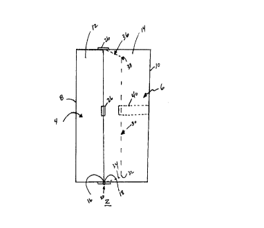
101520CA 02264478 2000-05-09ARTICLE OF LUGGAGEHAVING DIVIDER FOR OPPOSING SECTIONS1. ' 1 f InvThis invention relates to luggage, and, more particularly, to a suitcasehaving a clothing panel or a divider panel therein. The invention also relates to adivider for luggage.2. Qckground InformationIt is known to employ an internal panel in luggage, such as asuitcase. In some suitcases, an internal clothing panel is employed to form a sub-compartment for holding clothing, such as a suit, dress or coat, therein. In othersuitcases, an internal divider panel is employed to form a pair of separate sub-compartments for holding articles, such as clothing or other personal belongings,therein.United States Patent No. 1,954,607 shows a conventional, non-upright, hand luggage case having a main or bottom section, a cover or top section,and an internal cover or partition. With the bottom section on a horizontal surface,after the hand luggage case is opened, the free portion of the partition rests onsupports or brackets carried by the side walls of the bottom section. When accessto the bottom section is desired for paclcing and unpacking, the partition may bereleasably held in its raised or open position by engaging a member on theundersurface of the partition in a keeper on the inside surface of the top section. Inthis manner, a suit which is carried in the top section may be enclosed therein bythe partition.United States Patent No. 2,206,564 shows a carrying case including abody section which is hinged together with a cover or wardrobe section. A curtainis fastened at its upper end to the top wall of the wardrobe section and has fastening101520253035CA 02264478 2000-05-09â7l548-205straps carrying socket members adapted to be engaged with ballmembers secured to the body section.United States Patent No.case including two complementary or matching sections2,245,999 shows a luggageconnected by a hinge. A dust curtain panel, hingedly mountedat an edge of the bottom wall of one of the two sections, maybe moved into place as a cover for that section. In oneembodiment, the dust curtain panel is mated with an edge stripby slide fastener elements.One disadvantage of internal panels for luggage isthat such panels may contribute to wrinkles in clothing housedin the adjacent internal luggage compartments.Another disadvantage is that internal panels maypresent fixed boundaries which limit the volume of theadjacent internal luggage compartments.Accordingly, there is room for improvement ininternal panels for luggage.SUMMARY OF THE INVENTIONThis invention provides a suitcase comprising: afirst opposed section and a second opposed section, eachhaving an outer panel and a circumferential wall with a firstedge and a plurality of second edges, the first edges beinghingedly connected for movement of the opposed sectionsbetween an open position, in which access to at least one ofthe opposed sections is provided, and a closed position, inwhich the edges of the two circumferential walls are injuxtaposition; at least one closure engaging the first andsecond opposed sections and selectively holding the secondedges of the circumferential walls in juxtaposition; a dividerpositioned within said suitcase to at least partially dividethe opposed sections from each other when in the closedposition thereof, said divider having one end flexiblytethered to one of the circumferential walls and being movableinto and out of one of the opposed sections; and at least oneslack connector connected to one of the circumferential wallsand positioned to selectively and flexibly connect the otherend of the divider to the last said circumferential wall.CA 02264478 2000-05-09~7l548-205..2a_The suitcase may include at least one retainer connected toone of the opposed sections and positioned to engage thedivider and draw it toward the outer panel of that opposedsection.1015202530CA 02264478 2000-05-0971548-205-3-A number of preferred reï¬nements include providing a dividerincluding a rigid frame deï¬ning a periphery, and a ï¬exible membrane engaging theperiphery of the rigid frame. The rigid frame may be a wire frame, and theï¬exible membrane may be a soft fabric engaging the wire frame to form a generallyflat surface.The divider may form clothing panel means, and at least one slackconnector may be positioned to connect the free end of the clothing panel means toone of the circumferential walls to at least substantially close one of the opposedsections.One of the circumferential walls may have an interior surface withmeans for holding a hanger. The hanger may be a hanger for a suit, and theinterior surface of one of the circumferential walls may have means for securing aportion of the suit. The clothing panel means may include a first surface disposedtoward the outer panel of one of the opposed sections, and an opposite secondsurface disposed toward the outer panel of the other opposed section. The clothingpanel means may further include means for securing another portion of the suit.The first surface of the clothing panel means may have at least one pocket. Theinterior surface of one of the circumferential walls may have at least one pocket.The retainer may be positioned to engage the divider to substantiallyclose one of the opposed sections. The first opposed section may have a ï¬rstvolume with an article therein, and the second opposed section may have a secondvolume. The retainer, when positioned to engage the divider and draw it towardthe outer panel of the ï¬rst opposed section, may decrease the first volume andincrease the second volume. The second opposed section may have an interiorsurface with at least one pocket for holding another article.The suitcase may be an upright suitcase in which the ï¬rstopposed section is a rear section having a rear panel, and the second opposedsection is a front section having a front panel. The at least one slack connector maybe positioned to connect the free end of the divider to the circumferential wall ofone of the front and rear sections to at least substantially close one of thosesections.101520253035CA 02264478 2000-05-09â7l548-205Another aspect of the invention provides a dividerfor a suitcase having a first section and a second sectionwhich opposes said first section, with one of the first andsecond sections having a first interior surface, a secondinterior surface which opposes said first interior surface,and at least one slack connector connected to said secondinterior surface, said divider comprising: a rigid framedefining a periphery having a first end and a second end, aflexible membrane, means for engaging said flexible membranewith the periphery of the rigid frame, means for flexiblytethering said divider at the first end of the periphery tothe first interior surface of said suitcase, and at least oneslack connector at the second end of the periphery positionedto selectively and flexibly connect to said at least oneslack connector of said suitcase.The flexible membrane may include a first flexiblemembrane, a second flexible membrane, and a peripheral bordermember which is attached to the peripheries of the first andsecond flexible membranes, with the rigid frame between theflexible membranes. Preferably, the rigid frame is enclosedbetween the flexible membranes by the peripheral bordermember to substantially eliminate slack in the flexiblemembranes.Other details and advantages of the invention willbecome more apparent as the following description of a presentpreferred embodiment thereof proceeds.BRIEF DESCRIPTION OF THE DRAWINGSIn the accompanying drawings, a present preferredembodiment of the invention is illustrated in which:Figure 1 is a simplified side elvational View of asuitcase in a closed position embodying the present invention;Figure 2 is a side elevational View of the suitcaseof Figure l in an open position in which a portion of the rearcircumferential wall is broken away for clarity;Figure 3 is a more detailed front perspective viewof the suitcase of Figure 1;10CA 02264478 2000-05-09\7l548-205_.4a_Figure 4 is a more detailed front elevational viewof the suitcase of Figure 3;Figure 5 is a bottom view of the suitcase ofFigure 3;Figure 6 is a plan View of one side of the clothingpanel divider of Figure 1;Figure 7 is a plan View of the other side of theclothing panel divider of Figure 6;Figure 8 is a plan view of the rear section of thesuitcase of Figure l with the clothing panel divider shown inphantom line drawing in accordance with one embodiment of theinvention;1015202530CA 02264478 2000-05-09â 5 - Abraham et al.Figure 9 is a plan view of the rear section and the divider of thesuitcase of Figure 1 in accordance with another embodiment of the invention;Figure 10 is a sectional view taken through line 10-10 of Figure 9,except that the slack connectors are disconnected;Figure 11 is a plan view of the front section of the suitcase of Figure1; andFigure 12 is a sectional view taken through line 12-12 of Figure 6.DQCRIPTION OF A PREFERRED EMBODIMENTAs employed herein, the term "luggage" is intended to include, butshall not be limited to, luggage, case, suitcase, carry~on case, travel case, garmentcarrier, dufï¬e and a wide range of other devices for lugging clothing, personalbelongings and other articles therein.As disclosed herein, the terms "top", "bottom", "left", "right","front" and "rear" are exemplary, non-limiting terms which are employed forconvenience of reference to the accompanying drawings.Referring to Figures 1 and 2, a simpliï¬ed exemplary upright suitcase2 is illustrated in a closed position and an open position, respectively. The suitcase2 includes an opposing front section 4 and an opposing rear section 6 having frontand rear outer panels 8,10 and front and rear circumferential walls 12,14,respectively. The walls 12,14 have respective bottom edges 16,18 which form aconventional hinged connection 20 with the corresponding edge of the other wall.As shown with the wall 12 in Figure 2, the walls 12,14 also have three free edges22,23,24. The bottom edges 16,18 are hingedly connected for movement of theopposing sections 4,6 between an open position (shown in Figure 2) in which accessto one or both of the opposing sections 4,6 is provided and a closed position (shownin Figure 1) in which the four edges (16 or 18 and 22,23,24) of each of thecircumferential walls 12,14 are in juxtaposition.As shown in Figure 1, oneor more closures 26 engage the front andrear sections 4,6 and selectively hold the free edges 22,23,24 of the circumferentialwalls 12,14 in juxtaposition. Preferably, as shown in Figure 3, a slide closure 28,such as a zipper, may be provided about the edges 22,23,24 for opening and closingthe suitcase 2, although any suitable closure (e. g. , fastener, device for securing freeedges of circumferential walls in juxtaposition) known to those skilled in the art1015202530CA 02264478 2000-05-09â 6 - Abraham et al.may be provided. The zipper 28 is employed to selectivelyrelease the free edges22,23,24 of the circumferential walls 12,14 to permit access to one or both of thefront and rear sections 4,6 by a user. As a further reï¬nement, as shown in Figure5, the zipper 28 is preferably provided about portions of the bottom edges 16,18and, hence, extends around three sides and part of the fourth side of the suitcase 2.A divider panel 30 (shown in hidden line drawing in Figure 1) ispositioned within the suitcase 2 to at least partially divide portions or all of theopposing front and rear sections 4,6 from each other when in the closed position.The divider panel 30 has a bottom end 32 ï¬exibly tethered to the bottom portion ofthe rear circumferential wall 14 by a ï¬exible tether 34, and is movable into (shownin Figure 1) and out of (shown in Figure 2) the rear section 6. Although theexemplary divider panel 30 is ï¬exibly tethered to the rear circumferential wall 14, itwill be appreciated that, alternatively, the panel 30 may similarly be ï¬exiblytethered to the front circumferential wall 12 by a front ï¬exible tether (not shown).As best shown in Figure 2, one or more slack connectors 36 areconnected to the top portion of the rear circumferential wall 14 and are positionedto selectively and ï¬exibly connect the top end 38 of the divider panel 30 to thiscircumferential wall 14. As shown in Figure 1, one or more retainers 40 (shown inhidden line drawing) are connected to the rear section 6 and are positioned toengage the divider panel 30 and draw it toward the rear outer panel 10 of the rearsection 6. Although the exemplary divider panel 30 is selectively and ï¬exiblyconnected to the rear circumferential wall 14 and is drawn toward the rear outerpanel 10 by the retainers 40 connected to the rear section 6, it will be appreciatedthat, alternatively, the panel 30 may similarly be selectively and ï¬exibly connectedto the front circumferential wall 12 by front slack connectors (not shown) and/ormay be drawn toward the front outer panel 8 by front retainers (not shown).Referring to Figures 3 and 4, a detailed front perspective view and afurther detailed front elevational view, respectively, of the suitcase 2 are illustrated.The front and rear outer panels 8,10 and the rear circumferential wall 14 arepreferably made of soft, ï¬exible material, such as fabric. Also, the rearcircumferential wall 14 is preferably provided with a rigid internal spine (notshown) (e.g., a thermoplastic material, any suitably rigid material) extending arounda central portion thereof.1015202530CA 02264478 2000-05-09-7-As shown in Figure 5, the rear circumferential wall 14 has a bottomportion 41 and may have a roller mechanism mounted thereto. The exemplaryrollers 42,44 are preferably positioned at the junction of rear panel 10 and thebottom portion 41 of the rear circumferential wall 14. The rollers 42,44 arepositioned to at least partially support the weight of the suitcase 2 when in theupright, or at-rest, position of Figure 4. In a preferred embodiment, legs 46,48 areprovided on the bottom portion 41 of the rear circumferential wall 14 to support theremainder of the weight of the suitcase 2 when in the upright position. The rollers42,44 are operable to enable rolling movement of the suitcase 2 across a surface(not shown) in an inclined position (not shown).A retractable push/pull handle 50, shown in Figure 4, may beemployed by the user to effect rolling movement of the suitcase 2. The push/pullhandle 50 is preferably a rigid handle having two legs 52,54 and a gripping member56. The handle 50 is alternately retractable into (Figure 3) and extendable out of(Figure 4) the volume of the suitcase 2. To enable retraction and extension, thehandle 50 preferably includes an extension portion and a carrier (not shown)supported by the rigid spine (not shown). The carrier may include a pair of tubes(not shown) to telescopically receive the legs 52,54 therein for retraction. Such aretraction and extension structure is known to those skilled in the art.The suitcase 2 may include one or more carry handles mounted onone or more surfaces thereof, such as carry handle 58 mounted on the top portion60 of the rear circumferential wall 14 and/or carry handle 62 mounted on the sideportion 64 of the rear circumferential wall 14. The carry handles 58,62 may beemployed by the user to grasp the suitcase 2 and lift it, thereby supporting theentire weight thereof. The carry handles 58,62 may be of any type known to thoseskilled in the art. Preferably, to permit either of the carry handles 58,62 to fullysupport the weight of the suitcase 2 and its contents, the top and side portions 60,64are rigid. _Referring to Figure 6, a plan view of the front side 66 of the dividerpanel 30 is illustrated. The divider panel 30 is preferably formed from a rigid wireframe 68 (shown in hidden line drawing) defining a periphery and a membrane 70engaging the periphery of the rigid wire frame 68 to form a generally flat surface.The membrane 70 is preferably formed over the rigid wire frame 68 by employingAbraham et al.1015202530CA 02264478 2000-05-09- 8 - Abraham et al.a front soft fabric membrane 72 and a rear soft fabric membrane 74 (bothmembranes 72,74 are shown in Figures 10 and 12) along with a peripheral fabricborder 76 suitably attached (e. g. , as sewn by exemplary stitching 77 in Figure 12)to three edges 78,80,82 at the respective left, top and right peripheries of themembranes 72,74. The membranes 72,74 are further sewn together, without theborder 76, at the bottom edge 84. Preferably, the rigid wire frame 68 is enclosedbetween the membranes 72,74, with the sewn border 76 at edges 78,80,82 and thesewn membranes at edge 84 substantially eliminating and, preferably minimizing,any slack in the membranes 72,74 to render them suitably taut about the four sidesof the exemplary frame 68.At the bottom end 32 of the divider 30, the membranes 72,74 extendbeyond the bottom edge 84 to form the ï¬exible tether 34 of Figures 1 and 2.Preferably, the membranes 72,74 are further sewn together, with the border 76, atthe bottom edge 85 of the tether 34. Although the exemplary divider panel 30 isï¬exibly tethered to the bottom portion of the rear circumferential wall 14 of thesuitcase 2, it will be appreciated that, alternatively, the panel 30 may similarly beï¬exibly tethered to the top portion.Also referring to Figure 1, the slack connectors 36 (shown inphantom line drawing in Figure 6) preferably include a ï¬exible member 86 having atop end attached to the rear circumferential wall 14 and a bottom end attached to alatch member 88. Similarly, the top end 38 of the divider panel 30 includes slackconnectors 90 which preferably include a ï¬exible member 92 having a bottom endattached to the front soft fabric membrane 72 and a top end attached to a latchmember 94. As shown in Figure 8, the two pairs of mating latch members 88,94are engaged to connect the top free end 38 of the divider panel 30 to the rearcircumferential wall 14 and, hence, at least substantially close the rear section 6.As shown in Figure 2, the slack connectors 36,90 are positioned to selectively andï¬exibly connect the top end 38 of the divider panel 30 to the rear circumferentialwall 14. Preferably, the length of the slack connectors 36,90, from thecircumferential wall 14 to the top end 38 of the divider 30, is about the same lengthas that of the tether 34.Continuing to refer to Figure 6, the divider panel 30 includes aplurality of adjustable straps 96,98 attached to the left and right sides thereof. As1015202530CA 02264478 2000-05-0971548-205-9-shown with the strap 98, the straps 96,98 include ï¬exible members 100,102 having theirinner ends attached to mating latch members 104,106, respectively, and having theirouter ends sewn to the edges of the border 76. The straps 96,98 may advantageously beemployed to secure or release different portions of an article of clothing, such as theexemplary suit 108 (shown in phantom line drawing).Referring to Figure 7, a plan View of the rear side of the divider panel 30is illustrated. Preferably, the rear side includes one or more of a mesh pocket 110 and/orplural fabric pockets 112,114 for storing various articles, such as clothing or personalbelongings therein. The mesh pocket 110 includes a top mesh portion 116, a bottommesh portion 118 and a slide closure 120, such as a zipper, provided to open and closethe mesh pocket 110. The edges of the top and bottom mesh portions 116,118 aresuitably attached to the rear soft fabric membrane 74 and/or the edges of the border 76.The fabric pockets 112,114 preferably have elastic members 122,124, respectively, tosuitably retain other articles within those pockets.Referring to Figure 8, a plan view of the rear section 6 of the suitcase 2 isillustrated with the divider panel 30 (shown in phantom line drawing) ï¬inctioning inaccordance with one embodiment of the invention. In this embodiment, the retainers 40of Figure 1, which are shown as exemplary adjustable straps 126,128, are connected tothe rear section 6 and positioned to engage articles 130,132 (e. g., clothing, personalbelongings), respectively, behind the panel 30. Also, the slack connectors 36,90 areemployed to connect the free top end 38 of the divider panel 30 to the circumferentialwall 14 to at least substantially close the rear section 6. In this manner, other articles,such as 134, which are not engaged by the retainers 40 of Figure 1 or the straps 126,128of Figure 8, are held in the rear section 6 by the divider panel 30 when the suitcase 2 isopened (shown in Figure 2) and when the slack connectors 36,90 are engaged to at leastsubstantially close the rear section 6.Referring to Figure 9, a plan View of the rear section 6 and the dividerpanel 30 are illustrated with the divider panel 30 functioning in accordance with anotherembodiment of the invention. In this embodiment, the retainers 40 of Figure 1, whichare shown as exemplary straps 126,128 in Figure 9, are connected to the rear section 6and are positioned to engage the dividerpanel 30 and draw it1015202530CA 02264478 2000-05-0971548-205.. 10 _toward the rear outer panel 10 (shown in Figure l) of the rear section 6 in the mannerdiscussed above in connection with Figure 1. Articles (e.g., clothing, personalbelongings), such as 136 (shown in hidden line drawing), which are not engaged by theretainers 40 of Figure l or the straps 126,128, are held in the rear section 6 by thedivider panel 30 when the suitcase 2 is opened (shown in Figure 2). Typically, in thisembodiment, the slack connectors 36,90 are engaged to at least substantially close therear section 6, and the straps 96,98 (shown in Figure 6) of the divider 30 are not beemployed.It will be appreciated that the exemplary divider panel 30, as preferablyformed from the rigid wire frame 68 and the front and rear soft fabric membranes 72,74,functions to hold articles, such as clothing, in place in the rear section 6 withoutsubjecting such clothing to wrinkling which might otherwise be caused by other holders,such as the straps 126,128. Furthermore, the ï¬exible tether 34 and the slack connectors36,90 advantageously permit the retainers 40 of Figure l or the straps 126,128 of Figure9, to be employed adjust (i. e., decrease or increase) the storage volume of the rearsection 6 and, thus, increase or decrease, respectively, the storage volume of the frontsection 4 of Figure l, by adj ustably engaging the divider panel 30 and suitably drawingit toward the outer panel 10 (shown in Figure 1) of the rear section 6.Referring to Figure 10, the front section 4, the rear section 6 and thedivider panel 30 are illustrated, with the divider panel 30 ï¬mctioning in accordance withanother embodiment of the invention. This embodiment is similar to the embodiment ofFigure 9, except that the slack connectors 36,90 are disconnected and/or are notemployed.The front soft fabric membrane 72 of the divider 30 is disposed towardthe front outer panel 8 of the front section 4 and the rear soft fabric membrane 74 isdisposed toward the rear outer panel 10 of the rear section 6. By suitably positioningarticles, such as 138, the retainers 40 of Figure 1 or the straps 126,128 of Figure 10 maybe employed to engage the divider panel 30 and, thus, substantially close the rear section6 without the need to employ the slack connectors 36,90. Furthermore, the ï¬exibletether 34 advantageously permits the retainers 40 of Figure 1 or the straps 126,128 ofFigure 10, to be employed to decrease or increase the storage volume of the rear section6 and,thus, increase or1015202530CA 02264478 2000-05-09-11- A Abraham et al.decrease, respectively, the storage volume of the front section 4 for an article, suchas 140, by adjustably engaging the divider panel 30 and suitably drawing it towardthe outer panel 10 of the rear section 6.Referring to Figure 11, a plan view of the front section 4 of thesuitcase 2 is illustrated. The front section 4 includes a plurality of adjustable straps142,144 attached to the left and right sides of front section 4. As shown with thestrap 142, the straps 142,144 include ï¬exible members 146,148 having their innerends attached to mating latch members 150,152, respectively, and having their outerends sewn to the inner edges of the front section 4. The straps 142,144 mayadvantageously be employed to secure and release different portions of an article ofclothing, such as the exemplary suit 153 (shown in phantom line drawing).The top interior surface of the front section 4 has a loop member 154connected thereto for holding a hanger 156 (shown in phantom line drawing) for thesuit 153. It will be appreciated that the suit 108 of Figure 6 and the suit 153 ofFigure 11 may be a single article of clothing (e.g., a suit, dress, coat) which ishung by the hanger 156, with different portions of this article of clothing held bythe straps 144,142 of Figure 11 and the straps 96,98 of Figure 6, such that, forexample, the strap 144 holds the top portion of the article of clothing, below thehanger 156, and the strap 98 holds the bottom portion of that article of clothingwhich is folded between the strap 142 of the front section 4 and the strap 96 of thedivider panel 30, such that the divider panel 30 functions as a clothing panel or"suiter". In such a configuration, it will be appreciated that when the slackconnectors 36,90 of Figure 6 selectively and ï¬exibly connect the top end 38 of thedivider panel 30 to the rear circumferential wall 14 (e.g., as shown in Figure 1),and when the upright suitcase 2 is opened, the article of clothing, secured by someor all of the straps 144,142,96,98, is accessible by the user, while other articles(e. g. , article 134) within the rear section 6 (shown in Figure 8), may beadvantageously held therein by the divider panel 30.Continuing to refer to Figure 11, the interior surface of the frontsection 4 preferably has at least one pocket for holding other articles. Theexemplary mesh pocket 158 includes a left mesh portion 160, a right mesh portion162 and a slide closure 164, such as a zipper, provided to open and close the meshpocket 158. The edges of the left and right mesh portions 160,162 are suitably10152025CA 02264478 2000-05-09- 12 - Abraham et al.attached to the interior surface of the front section 4 to enclose the pocket 158.When an article (e.g., 140 of Figure 10) is stored in the pocket 158, the straps144,142 need not be employed, although it will be appreciated thatthe straps144,142 may advantageously be employed to further restrain the article within thepocket 158. _Referring to Figures 3-5 and 10, the front circumferential wall 12 hasfour sides and ispreferably expandable and contractible. As best shown in Figure4, a slide closure 165, such as a zipper, is provided about all four sides of the frontcircumferential wall 12. When the zipper 165 is closed (shown in Figures 3-5), thefront circumferential wall 12 is in its fully contracted position.On the other hand, when the zipper 165 (shown in hidden linedrawing in Figure 10) is opened, the front circumferential wall 12 expands toaccommodate the article 140 within the pocket 158, although such expansion mayalso be employed to accommodate other articles, such as the suit 153 of Figure 11.When the zipper 165 is opened, the parting of the zipper halves 166,168 uncovers aï¬exible portion 170 of the front circumferential wall 12 which unfolds toaccommodate the articles within the front section 4. Otherwise, when the zipper165 is closed to engage the zipper halves 166,168 (e.g. , as shown in Figure 4), theï¬exible portion 170 is folded (e.g., as shown in Figure 11-) behind the engagedhalves 166,168 of the closed zipper 165 to full contract the front circumferentialwall 12. It will be appreciated that the zipper 165 may also be opened toaccommodate other articles (not shown) within the front pockets 172,174 of thefront outer panel 8 of Figure 4.Whereas particular embodiments of the present invention have beendescribed above for purposes of illustration, it will be appreciated by those skilledin the art that numerous variations in the details may be made without departingfrom the invention as described in the appended claims.