Language selection

Search

Patent 2264702 Summary

Third-party information liability

Some of the information on this Web page has been provided by external sources. The Government of Canada is not responsible for the accuracy, reliability or currency of the information supplied by external sources. Users wishing to rely upon this information should consult directly with the source of the information. Content provided by external sources is not subject to official languages, privacy and accessibility requirements.

Claims and Abstract availability

Any discrepancies in the text and image of the Claims and Abstract are due to differing posting times. Text of the Claims and Abstract are posted:

  • At the time the application is open to public inspection;
  • At the time of issue of the patent (grant).
(12) Patent: (11) CA 2264702
(54) English Title: FILTER WITH HOUSING
(54) French Title: FILTRE A CARTER
Status: Deemed expired
Bibliographic Data
(51) International Patent Classification (IPC):
  • F02M 35/024 (2006.01)
  • B01D 46/02 (2006.01)
  • B01D 46/24 (2006.01)
  • B01D 46/42 (2006.01)
  • B60H 3/06 (2006.01)
(72) Inventors :
  • BULLINGER, ALFRED (Germany)
  • LEONHARDT, MICHAEL (Germany)
  • SCHOLL, HANS-PETER (Germany)
(73) Owners :
  • FILTERWERK MANN & HUMMEL GMBH (Germany)
(71) Applicants :
  • FILTERWERK MANN & HUMMEL GMBH (Germany)
(74) Agent: NORTON ROSE FULBRIGHT CANADA LLP/S.E.N.C.R.L., S.R.L.
(74) Associate agent:
(45) Issued: 2005-09-13
(86) PCT Filing Date: 1997-07-11
(87) Open to Public Inspection: 1998-02-26
Examination requested: 2002-07-10
Availability of licence: N/A
(25) Language of filing: English

Patent Cooperation Treaty (PCT): Yes
(86) PCT Filing Number: PCT/EP1997/003678
(87) International Publication Number: WO1998/007978
(85) National Entry: 1999-02-22

(30) Application Priority Data:
Application No. Country/Territory Date
196 33 896.4 Germany 1996-08-22

Abstracts

English Abstract


A filter with housing consists of a filter element (12) shaped as a round
cartridge, a housing (10) and a housing lid (11). The housing
has a raw air inlet (19) and a pure air outlet (20). The pure air outlet is
provided with a connecting pipe (16) on which the filter element
(12) is arranged. The filter element has a radial gasket at its side that
faces the connecting pipe and is guided through the housing at the
side opposite to the connecting pipe.


French Abstract

L'invention concerne un filtre à carter comprenant un élément filtrant (12) sous forme de cartouche ronde, un carter (10), ainsi qu'un couvercle de carter (11). Le carter comporte un orifice d'entrée d'air avant filtration (19) et un orifice de sortie d'air pur (20) qui est muni d'une tubulure de raccordement (16) sur laquelle est monté l'élément filtrant (12). Ce dernier comporte, sur son côté faisant face à la tubulure de raccordement, une garniture d'étanchéité radiale et est guidé au niveau de la face opposée à la tubulure de raccordement à travers le carter.

Claims

Note: Claims are shown in the official language in which they were submitted.


5


Claims:


1. A filter with housing, comprising a filter element in the form of a
cylindrical cartridge, a housing and a housing lid, wherein the housing has
a raw air inlet and a clean air outlet, and the clean air outlet is provided
with a connecting support on which the filter element is arranged, the filter
element has a radial gasket on the side facing the connecting support, and
the filter element on the side opposite from the connecting support is guided
by a sliding element provided on the housing, said housing lid including a
securing element and said sliding element including a locking element,
wherein the securing element engages the locking element when the
housing lid is closed thereby preventing movement of the sliding element.

2. A filter with housing according to claim 1, wherein said securing
element fixes the axial position of the filter element.

3. A filter with housing according to claim 1, wherein the sliding
element carries a support guide which engages in an axial opening of the
filter element.

4. A filter with housing according to claim 1, wherein the sliding
element is provided with at least one stop projection which defines a range
of displacement of the sliding element relative to the housing.

5. A filter with housing according to claim 1, wherein a blocking
element, which prevents closure of the housing lid whenever the filter
element is not properly installed, is provided on the sliding element.

6. A filter with housing according to claim 1, wherein the filter element
is provided with a support body, and the support body cooperates with a
connecting piece to seal a clean air chamber of the filter.

7. A filter with housing according to claim 6, wherein a sealing gasket is
provided between the support body and the connecting piece.


6


8. A filter with housing according to claim 7, wherein said sealing
gasket is an O-ring gasket.

Description

Note: Descriptions are shown in the official language in which they were submitted.

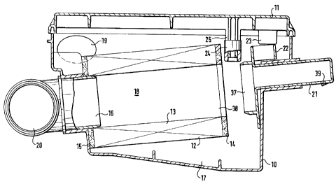
CA 02264702 2004-09-22Filter with HousingDescriptionThe invention relates to a filter with housing.EP 317 417 A2 discloses a filter with housing in which a filter cartridge is clamped in ahousing and can be fixed by means of a cam and a spring element. In order to fix the filtercartridge reliably in the housing, high restraining forces are necessary. These are producedby means of appropriate mounting elements.The filter cartridge is sealed off axially. This means that a certain compensation fortolerance is necessary since a filter cartridge exhibits particular length tolerances.Likewise, additional mechanical elements are necessary for this tolerance compensation.The object of the invention is to provide a filter with housing which can be manufacturedwith a low expenditure in construction components; which does not require any elementscompensating for tolerance, and which avoids the disadvantages noted above.This object is achieved by providing a filter comprising a filter element in the form of acylindrical cartridge, a housing and a housing lid, wherein the housing has a raw air inletand a clean air outlet, and the clean air outlet is provided with a connecting support onwhich the filter element is arranged, the filter element has a radial gasket on the side facingthe connecting support, and the filter element on the side opposite from the connectingsupport is guided by a sliding element provided on the housing, the housing lid including asecuring element and the sliding element including a locking element, wherein the securingelement engages the locking element when the housing lid is closed and thereby preventsmovement of the sliding element.The significant advantage of the invention lies in that the construction in accordance withthe invention leads to reliable support of the filter element, both in the area of theconnecting piece as well as on the opposite side. Several possibilities exist for fastening thefilter element on the opposite side. For one, it is possible to support the filter in theperipheral area at the housing wall. Another possibility, as described in anotherembodiment of the invention, is to provide an axial stop for the filter element, whichdirectly or indirectly fixes the axial position of thewo 98/07978 _ CA 02264702 1999'°2'22 PCT/EP97/036782filter element. This axial stop can be constructed as a manually actuatable sliding element, or ahinge or a flap, by means of which the support on the housing ensues. In a sliding element, tl1eguidance of the filter element occurs by means of appropriate guiding surfaces or, inaccordance with further development, through an axial opening of the filter element. into whicha guiding support of the sliding element engages. So that the position of the sliding elen1e11t isdefined within a certain area, the sliding element can be fitted with a detent projection whichforms a stop on the housing in accordance with another embodiment of the invention.It is necessaiy to assure that operation of the internal combustion engine without the filter isprevented, especially when the filter is used for the intake air of an internal combustion engine.This can be achieved in accordance with one embodiment of the invention, in that a blockingelement is provided on the sliding element which prevents closure of the housing lid if no filterelement or an improperly installed filter element is present. Only when the filter element isproperly installed, can the lid be close(l correctly, such that with a closed lid it is assured that afilter element is installed properly and thus the intake air will be guided through the filterelement.In accordance with further embodiment, it is proposed to provide the filter element. with asupport body and to effect. the seal on the clean air side by means of the support body. Thesupport body has the advantage that especially high differential pressures can be absorbedeffectively. This support body can, for example, have a gasket in the form of an O-ring gasket,which effects the sealing between the raw air chamber and the clean air chamber.These and further characteristics of preferred embodiments of die invention are found notonly in the claims, but also appear from the specification and the drawings, whereby theindividual features can each be realized individually or together in various subcombinations inembodiments of the invention and in other fields, and may represent advantageousembodiments which are themselves worthy of protection and for which protection is claimedhere.The invention is explained below in further detail with reference to illustrative embodiments.Figure 1 shows a sectional view of a filter with housing with an opened lid,Figure 2 shows the filter with housing shown in Figure l with a closed lid,Figures 8 a through c show various views of a filter system with a support tube.wo 98/07978 CA 02264702 1999'02'22 PCT/EP97/036783The filter shown in Figure 1 comprises a housing 10, a housing lid 11, and a filter element 12which is arranged in the housing. The filter element 12 is a paper filter 13 wit11 zig-zag-shapedfolds in a star configuration. The paper filter 13 has end discs 14, 15 on its end faces. The enddisc 15 is slid over a connecting piece 16 of the housing 10 and produces a radial sealingbetween the raw air chamber 17 and the clean air chamber 18. The raw air flows into the rawair chamber 18 through the raw air inlet 19. While the entrained particles are filtered out bythe filter element 12, the filtered air leaves the filter system through the clean air chamber 18and the connecting piece 16, as well as the clean air tube 20. The housing is equipped with asliding element 21 for stabilizing the filter element 12. The sliding element 21 is located in theposition shown here to install or remove the filter element 12. The sliding element. has ablocking element 22 which in the position shown prevents closure of the lid 11 which isprovided with a projection 23. This means that with an opened sliding element 21, it is notpossible to use the housing filter. Instead, this position is only suitable for exchanging the filterelement 12. The housing lid 11 also has a securing element 24. This consists of a rod 25 andan elastomer cap 26 fastened thereon.The manner of operation of the securing element 24 is explained in more detail with referenceto Figure 2. Corresponding parts are identified by the same reference numbers.The operational position is attained as soon as the sliding element 21 is moved to the filterelement 12. This operational position can be seen in Figure 2. The right side sealing of thefilter element between the raw air chamber and the clean air chamber also ensues here bymeans of a support guide 27 which produces a radial seal in conjunction with the end disc 14.In the position of the sliding element 21 shown here, the securing element 24 can engage insidethe blocking element 22 and prevents opening of the sliding element 21. At the same time, anorderly closing of the housing lid 11 is now possible. The housing lid 11 is secured to thehousing with tensioning clamps or snap closures.The elastomer cap 26 on the rod 25 creates a weak connection between the lid and the slidingelement 21 and prevents a transfer of vibrations or shaking. In addition, the weak connectionhas a t.olerance-compensating effect.The different views a - c of Figure 3 show a filter system with a support tube. A filter housing27 is provided with a housing lid 28. The filter element 30 is l()cated on a support tube 29 inthe filter housing. The support tube is connected to the clean air connecting piece 32 via awo 98/07978 CA 022647“ ””'°2'“ PCT/EP97/036784sealing element 31. The filter element can be ce11tere(l or prepositioned adjacent the ribs 33,34 of the filter housing. T 0 install the filter element 30, this can be moved by means of asuitable medium, for example with a lever 35, into the axial target position shown here. Fordisassembly, the filter element is pulled from this target position and removed in an upwarddirection.The housing lid is fitted with a safety device 36. This safety device comprises a projectionextending into the interior of the housing. To the extent. that the filter element 30 is not in thetarget position, this projection prevents the closing of the housing li(l.As shown in Figure 3b, the filter element is arranged asymmetrically in the housing. The lid 28is provided with a central closure 36 according to Figure 3C. This central closure is forexample a bayonet plug and enables a particularly rapid and trouble-free opening an(l closingof the housing lid 28.
Representative Drawing
A single figure which represents the drawing illustrating the invention.
Administrative Status

For a clearer understanding of the status of the application/patent presented on this page, the site Disclaimer , as well as the definitions for Patent , Administrative Status , Maintenance Fee  and Payment History  should be consulted.

Administrative Status

Title Date
Forecasted Issue Date 2005-09-13
(86) PCT Filing Date 1997-07-11
(87) PCT Publication Date 1998-02-26
(85) National Entry 1999-02-22
Examination Requested 2002-07-10
(45) Issued 2005-09-13
Deemed Expired 2014-07-11

Abandonment History

There is no abandonment history.

Payment History

Fee Type Anniversary Year Due Date Amount Paid Paid Date
Application Fee $300.00 1999-02-22
Registration of a document - section 124 $100.00 1999-04-26
Maintenance Fee - Application - New Act 2 1999-07-12 $100.00 1999-06-28
Maintenance Fee - Application - New Act 3 2000-07-11 $100.00 2000-07-11
Maintenance Fee - Application - New Act 4 2001-07-11 $100.00 2001-06-21
Maintenance Fee - Application - New Act 5 2002-07-11 $150.00 2002-06-26
Request for Examination $400.00 2002-07-10
Maintenance Fee - Application - New Act 6 2003-07-11 $150.00 2003-06-27
Maintenance Fee - Application - New Act 7 2004-07-12 $200.00 2004-06-16
Final Fee $300.00 2005-04-22
Maintenance Fee - Application - New Act 8 2005-07-11 $200.00 2005-06-22
Maintenance Fee - Patent - New Act 9 2006-07-11 $200.00 2006-06-28
Maintenance Fee - Patent - New Act 10 2007-07-11 $250.00 2007-06-26
Maintenance Fee - Patent - New Act 11 2008-07-11 $250.00 2008-06-20
Maintenance Fee - Patent - New Act 12 2009-07-13 $250.00 2009-06-25
Maintenance Fee - Patent - New Act 13 2010-07-12 $250.00 2010-06-25
Maintenance Fee - Patent - New Act 14 2011-07-11 $250.00 2011-07-01
Maintenance Fee - Patent - New Act 15 2012-07-11 $450.00 2012-06-28
Owners on Record

Note: Records showing the ownership history in alphabetical order.

Current Owners on Record
FILTERWERK MANN & HUMMEL GMBH
Past Owners on Record
BULLINGER, ALFRED
LEONHARDT, MICHAEL
SCHOLL, HANS-PETER
Past Owners that do not appear in the "Owners on Record" listing will appear in other documentation within the application.
Documents

To view selected files, please enter reCAPTCHA code :


To view images, click a link in the Document Description column. To download the documents, select one or more checkboxes in the first column and then click the "Download Selected in PDF format (Zip Archive)" or the "Download Selected as Single PDF" button.

List of published and non-published patent-specific documents on the CPD .

If you have any difficulty accessing content, you can call the Client Service Centre at 1-866-997-1936 or send them an e-mail at CIPO Client Service Centre.


Document
Description 
Date
(yyyy-mm-dd) 
Number of pages   Size of Image (KB) 
Description 2004-09-22 4 186
Claims 2004-09-22 2 46
Representative Drawing 1999-05-07 1 12
Abstract 1999-02-22 1 54
Description 1999-02-22 4 176
Claims 1999-02-22 2 68
Drawings 1999-02-22 4 102
Cover Page 1999-05-07 1 44
Representative Drawing 2005-05-30 1 15
Cover Page 2005-08-17 1 44
Correspondence 1999-04-20 1 30
PCT 1999-02-22 12 433
Assignment 1999-02-22 3 89
Assignment 1999-04-26 2 69
Prosecution-Amendment 2002-07-10 1 35
Prosecution-Amendment 2004-09-22 5 184
Prosecution-Amendment 2004-03-22 2 59
Correspondence 2005-04-22 1 39
Prosecution-Amendment 2005-04-22 1 38
Prosecution-Amendment 2005-05-04 1 11