Language selection

Search

Patent 2264768 Summary

Third-party information liability

Some of the information on this Web page has been provided by external sources. The Government of Canada is not responsible for the accuracy, reliability or currency of the information supplied by external sources. Users wishing to rely upon this information should consult directly with the source of the information. Content provided by external sources is not subject to official languages, privacy and accessibility requirements.

Claims and Abstract availability

Any discrepancies in the text and image of the Claims and Abstract are due to differing posting times. Text of the Claims and Abstract are posted:

  • At the time the application is open to public inspection;
  • At the time of issue of the patent (grant).
(12) Patent: (11) CA 2264768
(54) English Title: DISPENSING CARTRIDGE
(54) French Title: CARTOUCHE DE DISTRIBUTION
Status: Deemed expired
Bibliographic Data
(51) International Patent Classification (IPC):
  • B65D 83/76 (2006.01)
  • B05C 17/005 (2006.01)
  • B65D 83/00 (2006.01)
(72) Inventors :
  • DANG, NGUYEN THAI (United States of America)
  • MORRIS, DAVID PAUL (United States of America)
(73) Owners :
  • PRC-DESOTO INTERNATIONAL, INC. (United States of America)
(71) Applicants :
  • COURTAULDS AEROSPACE, INC. (United States of America)
(74) Agent: BORDEN LADNER GERVAIS LLP
(74) Associate agent:
(45) Issued: 2002-12-03
(86) PCT Filing Date: 1997-09-12
(87) Open to Public Inspection: 1998-03-19
Examination requested: 1999-10-15
Availability of licence: N/A
(25) Language of filing: English

Patent Cooperation Treaty (PCT): Yes
(86) PCT Filing Number: PCT/US1997/016281
(87) International Publication Number: WO1998/011002
(85) National Entry: 1999-03-05

(30) Application Priority Data:
Application No. Country/Territory Date
08/712,397 United States of America 1996-09-13

Abstracts

English Abstract


A dispensing cartridge (10) is provided for viscous liquids, such as sealants.
The cartridge (10) includes an elongated tubular cylindrical housing (12)
defining an elongated interior chamber (16) having a cylindrical interior wall
(14). A dispensing nozzle (18) is formed at one end (20) of the housing (12)
and this dispensing nozzle (18) has an opening (22) open to the housing
chamber (16) which is less in cross-sectional size than the cross-sectional
size of the housing chamber (16). A substantially semi-spherical wall portion
(26) extends between the cylindrical wall (14) of the housing (12) and the
nozzle opening (22) while at least one reinforcing rib (28) extends outwardly
from an outer surface of the semi-spherical wall portion (26). This
reinforcing rib (28) not only reinforces the semi-spherical wall portion (26)
of the housing (12) but also enables the cartridge (10) to be used in a
standard caulking gun.


French Abstract

L'invention concerne une cartouche de distribution (10) destinée à des liquides visqueux tels que des produits d'étanchéité. La cartouche (10) comprend un logement cylindrique tubulaire allongé (12) définissant une chambre intérieure oblongue (16) présentant une paroi intérieure cylindrique (14). Une buse de distribution (18) est formée à une extrémité (20) du logement (12) et cette buse de distribution (18) présente un orifice (22) ouvrant sur la chambre (16) du logement, laquelle présente une taille de section inférieure à celle de la chambre (16) du logement. Une partie de paroi sensiblement semi-sphérique (26) s'étend entre la paroi cylindrique (14) du logement (12) et l'orifice (22) de la buse, tandis qu'au moins une nervure de renforcement (28) s'étend à l'extérieur d'une surface extérieure de ladite partie de paroi semi-sphérique (26). Cette nervure de renforcement (28) non seulement renforce la partie de paroi semi-sphérique (26) du logement (12) mais permet également d'utiliser la cartouche (10) dans un pistolet standard d'application de joint d'étanchéité.

Claims

Note: Claims are shown in the official language in which they were submitted.


-8-

Claims
1. A dispensing cartridge for a viscous liquid fluid comprising:
an elongated tubular housing defining an elongated interior chamber
having a cylindrical interior cylindrical wall with a first cross-sectional size and an
outer cylindrical wall,
a dispensing nozzle at one end of said housing, said nozzle having an
opening open to said interior chamber, said nozzle opening having a cross-sectional
size less than said cross-sectional size of said housing chamber,
said housing having a substantially semi-spherical wall portion extending
between said interior cylindrical wall and said nozzle opening, and
a plurality of radially extending and circumferentially spaced reinforcing
ribs extending from an outer surface of said semi-spherical wall portion, each rib
having an inner end integrally joined with said nozzle and an outer, axially elongated
end aligned with said outer cylindrical wall.

2. The invention as defined in claim 1 wherein said housing is made
of plastic.

3. The invention as defined in claim 1 wherein said housing, said
nozzle and said semi-spherical wall portion are of a one piece construction.

4. The invention as defined in claim 3 wherein said rib and said
housing are of a one piece construction.


-9-
5. The invention as defined in claim 1 wherein said at least one rib
has an axial end surface which lies in a plane perpendicular to a longitudinal axis of
said housing.

6. The invention as defined in claim 1 wherein each said rib extends
in a direction substantially perpendicular to a longitudinal axis of said housing.

7. The invention as defined in claim 1 and comprising a plunger
longitudinally slidably mounted in said interior chamber, said plunger having a shape
at one end complementary to said semi-spherical wall portion.

8. The invention as defined in claim 7 wherein said plunger has an
annular seal at each end, each annular seal sealingly engaging said interior cylindrical
wall of said housing.

9. The invention as defined in claim 7 wherein said plunger is made
of plastic.

10. The invention as defined in claim 9 wherein said plunger is of
a one piece construction.


-10-

11. The invention as defined in claim 7 and comprising a dasher
slidably positioned in said housing interior chamber between said plunger and said
semi-spherical wall portion.

12. The invention as defined in claim 11 wherein an end of said
dasher facing said semi-spherical wall portion is complementary in shape to said
semi-spherical wall portion.


Description

Note: Descriptions are shown in the official language in which they were submitted.

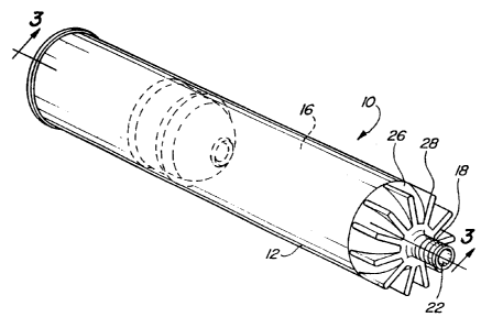
W0 98/1 1002101520CA 02264768 1999-03-05PCT/U S97] 16281- 1 -DISPENSING CARTRIDGEField of the InventionThe present invention relates generally to cartridges and, moreparticularly, to a dispensing cartridge for viscous liquids of the type utilized in caulkingguns .Background of the InventionThere are several different types of cartridges that are conventionallyused in caulking guns. In one type of cartridge, a cardboard cylindrical tube forms anelongated cylindrical chamber. One end of the chamber is enclosed by a flat end caphaving a dispensing nozzle extending outwardly therefrom. The material is containedwithin the interior of the cartridge while a plunger is also positioned within the housingchamber at a position spaced on the dispensing nozzle. Consequently, with thecartridge positioned in a caulking gun, displacement of the plunger forces the viscousmaterial contained within the cartridge out through the dispensing nozzle.In still a different type of cartridge, the cartridge housing, end cap anddispensing nozzle are of a one piece plastic construction. In all other respects,however, the plastic cartridge is the same as the cardboard cartridge.Conventionally, dispensing cartridges are manufactured in two standardsizes. One standard size fits a regular size caulking gun while, similarly, the largersize fits a large size caulking gun.One disadvantage of these previously known cartridges, however, is thatthe sharp corners formed between the flat end cap and the housing are subjected to aW0 98/1 1002101520CA 02264768 1999-03-05PCT/U S97/ 16281-2-great deal of stress during a dispensing operation. Such stress can result in crackingof the cartridge and/or other cartridge failure in use. Previously, however, it has notbeen possible to eliminate the sharp corners between the end cap of the cartridge andthe main housing of the cartridge and still allow the cartridge to be used in a standardcaulking gun.Summary of the InventionThe present invention provides a cartridge for viscous liquids whichovercomes all of the above-mentioned disadvantages of the previously known devices.In brief, the dispensing cartridge of the present invention comprises anelongated tubular housing defining an elongated interior chamber having a cylindricalinterior wall. A dispensing nozzle is formed at one end of the housing and thisdispensing nozzle has an opening open to the interior chamber of the housing whichis smaller in cross-sectional size than the cross-sectional size of the housing chamber.A substantially semi-spherical wall portion extends between the housingand the dispensing nozzle so that the housing adjacent the dispensing nozzle is in theform of a dome. This dome effectively eliminates sharp corners at the dispensing endof the housing and thus minimizes any possibility of cartridge cracking during use.In order to enable the dispensing cartridge to be utilized in a standardcaulking gun, at least one, and possibly several, radially extending ribs extendoutwardly from an outer surface of the semi-spherical wall portion adjacent the nozzle.These reinforcing ribs not only reinforce the structure of the cartridge housing at thenozzle end of the housing, but also form a generally planar surface which intersects theW0 98/1 1002101520CA 02264768 1999-03-05PCT/US97/16281-3-longitudinal axis of the cartridge substantially perpendicularly. As such, thereinforcing ribs enable the cartridge to be utilized in a standard caulking gun in theconventional fashion.A cylindrical plunger is positioned within the interior of the housing sothat displacement of the plunger simultaneously displaces material contained within thehousing chamber. This plunger, furthermore, includes a semi—spherical dome at its endwhich faces the nozzle and which is complementary to the semi—spherical wall portionof the cartridge. An optional dasher is also provided in the housing chamber betweenthe plunger and the nozzle when mixing of the plunger liquid is desired prior todispensing.Brief Description of the DrawingsA better understanding of the present invention will be had uponreference to the following detailed description, when read in conjunction with theaccompanying drawing, wherein like reference characters refer to like parts throughoutthe several views, and in which:FIG. 1 is an elevational view illustrating a preferred embodiment of thepresent invention;FIG. 2 is an elevational view illustrating a preferred plunger of thepresent invention;FIG. 3 is a longitudinal sectional view taken substantially along line 3-3in FIG. 1;W0 98/ 1 1002101520CA 02264768 1999-03-05PCT/US97/16281-4-FIG. 4 is a fragmentary sectional view taken substantially along circle4-4 in FIG. 3 and enlarged for clarity;FIG. 5 is an exploded view similar to FIG. 2 illustrating a plunger witha dasher;FIG. 6 is a longitudinal sectional view similar to FIG. 3, but illustratinga cartridge having a dasher; andFIG. 7 is an elevational view illustrating the cartridge mounted in acaulking gun.Detailed Description of the InventionWith reference first to FIGS. 1 and 3, a preferred embodiment of thecartridge 10 of the present invention is there shown and comprises an elongated tubularand cylindrical housing 12 having an interior cylindrical wall 14 (FIG. 3). Thehousing 12 thus defines a cylindrical interior housing chamber 16 in which a viscousfluid, such as a sealant, is contained.A dispensing nozzle 18 is provided at one end 20 of the housing. Thisnozzle 18 includes a dispensing passageway 22 and may be externally threaded asshown at 24. Furthermore, the cross-sectional area of the dispensing passageway 22is less than the cross-sectional area of the housing interior chamber 16 as best shownin FIG. 3.As best shown in FIG. 3, a semi-spherical wall portion 26 extendsbetween the housing 12 and the nozzle 18 thus forming a spherical dome at theW0 98/11002101520CA 02264768 1999-03-05PCT/US97/16281-5-dispensing end of the cartridge 10. Thus, the semi-spherical wall portion 26 minimizesthe stress caused by the previously known flat end caps on dispensing cartridges.Referring now especially to FIGS. 1 and 3, a plurality of radiallyextending reinforcing ribs 28 extend outwardly from an outer surface of the sphericalwall portion 26. These reinforcing ribs 28 provide two functions. First, thereinforcing ribs 28 reinforce and rigidify the spherical wall portion 26 and protect thespherical wall portion 26 against fracture or other failure in use.Secondly, the reinforcing ribs 28 form a generally planar surface (FIG.3) which lies in a plane substantially perpendicular to the longitudinal axis of thehousing 12. The outer radial periphery of the reinforcing ribs 28 are also substantiallyaligned with the outer cylindrical surface of the housing 12.As best shown in FIG. 7, the reinforcing ribs 28 thus enable thecartridge 10 to be utilized with a standard caulking gun 32. Thus, when positioned ina standard caulking gun, the reinforcing ribs 28 simulate a flat end of a previouslyknown conventional dispensing cartridge.With reference again to FIGS. 2 and 3, a cylindrical plunger 40 havingan annular seal 42 (see FIG. 4) at each end is longitudinally slidably disposed withinthe interior housing chamber 16. An end 44 of the plunger 40 facing the nozzle 18 issemi-spherical in shape and thus complementary to the internal shape of the semi-spherical wall portion 26. In a conventional fashion, axial displacement of the plunger40 through the cartridge housing 12 forces material contained within the housingchamber 16 out through the nozzle opening 22. Since the end 44 of the plunger 40 iscomplementary to the semi-spherical wall portion 26, the plunger 40 ensures thatWO 98/11002101520CA 02264768 1999-03-05PCT/US97/16281-6-virtually all of the material contained within the housing chamber 16 is dispensed outthrough the nozzle 18 when the plunger 40 is forced to the position shown in phantomline in FIG. 3.In the preferred embodiment of the invention, the housing 12, semi-spherical wall portion 26, nozzle 18 and reinforcing ribs 28 are all of a one pieceplastic construction. Similarly, the plunger 40 is also preferably of a one piece plasticconstruction.With reference now to FIGS. 5 and 6, an alternative embodiment of thepresent invention is there shown in which a mixing dasher 50 is disposed within thehousing chamber 16 in between the plunger 40 and the nozzle 18. The dasher 50includes both a semi—spherical surface 52 facing the nozzle 18 as well as a semi-spherical surface 54 on its end which faces the plunger 40. The semi—spherical surface52 is complementary to the wall portion 26 of the cartridge 10 while, similarly, thesemi—spherical surface 54 is complementary to the end 44 of the plunger 40. In thewell known fashion, the dasher 50 includes a plurality of openings 56 which enable thedasher 50 to be displaced through the housing chamber 16 thus intermixing the fluidcontained within the housing chamber 16. A rod 60 extending through the nozzle 18is utilized to axially move the dasher 52.From the foregoing, it can be seen that the present invention providesan improved cartridge of the type utilized with caulking guns which eliminates thepreviously known stress related problems from the previously known flat endedcaulking cartridges. Furthermore, the cartridge of the present invention, due to thereinforcing ribs 28, is still able to be used in a standard caulking gun.CA 02264768 1999-03-05W0 98/] 1002 PCT/US97/16281-7-Having described my invention, however, many modifications theretowill become apparent to those skilled in the art to which it pertains without deviationfrom the spirit of the invention as defined by the scope of the appended claims.We claim:
Representative Drawing
A single figure which represents the drawing illustrating the invention.
Administrative Status

For a clearer understanding of the status of the application/patent presented on this page, the site Disclaimer , as well as the definitions for Patent , Administrative Status , Maintenance Fee  and Payment History  should be consulted.

Administrative Status

Title Date
Forecasted Issue Date 2002-12-03
(86) PCT Filing Date 1997-09-12
(87) PCT Publication Date 1998-03-19
(85) National Entry 1999-03-05
Examination Requested 1999-10-15
(45) Issued 2002-12-03
Deemed Expired 2008-09-12

Abandonment History

There is no abandonment history.

Payment History

Fee Type Anniversary Year Due Date Amount Paid Paid Date
Registration of a document - section 124 $100.00 1999-03-05
Application Fee $300.00 1999-03-05
Maintenance Fee - Application - New Act 2 1999-09-13 $100.00 1999-08-26
Request for Examination $400.00 1999-10-15
Registration of a document - section 124 $50.00 2000-01-06
Maintenance Fee - Application - New Act 3 2000-09-12 $100.00 2000-08-18
Maintenance Fee - Application - New Act 4 2001-09-12 $100.00 2001-08-17
Maintenance Fee - Application - New Act 5 2002-09-12 $150.00 2002-08-20
Final Fee $300.00 2002-09-19
Maintenance Fee - Patent - New Act 6 2003-09-12 $150.00 2003-08-21
Maintenance Fee - Patent - New Act 7 2004-09-13 $200.00 2004-08-20
Maintenance Fee - Patent - New Act 8 2005-09-12 $200.00 2005-08-19
Maintenance Fee - Patent - New Act 9 2006-09-12 $200.00 2006-08-17
Owners on Record

Note: Records showing the ownership history in alphabetical order.

Current Owners on Record
PRC-DESOTO INTERNATIONAL, INC.
Past Owners on Record
COURTAULDS AEROSPACE, INC.
DANG, NGUYEN THAI
MORRIS, DAVID PAUL
Past Owners that do not appear in the "Owners on Record" listing will appear in other documentation within the application.
Documents

To view selected files, please enter reCAPTCHA code :


To view images, click a link in the Document Description column. To download the documents, select one or more checkboxes in the first column and then click the "Download Selected in PDF format (Zip Archive)" or the "Download Selected as Single PDF" button.

List of published and non-published patent-specific documents on the CPD .

If you have any difficulty accessing content, you can call the Client Service Centre at 1-866-997-1936 or send them an e-mail at CIPO Client Service Centre.


Document
Description 
Date
(yyyy-mm-dd) 
Number of pages   Size of Image (KB) 
Abstract 1999-03-05 1 60
Description 1999-03-05 7 234
Claims 1999-03-05 3 67
Drawings 1999-03-05 2 65
Cover Page 1999-05-11 1 57
Cover Page 2002-10-29 1 47
Representative Drawing 1999-05-11 1 8
Representative Drawing 2002-03-15 1 12
Fees 1999-08-26 1 55
Prosecution-Amendment 2000-06-16 1 41
Fees 2000-08-18 1 56
Correspondence 2000-12-14 3 90
Assignment 2000-01-06 5 181
Correspondence 2001-01-16 1 14
Correspondence 2001-01-16 1 16
Correspondence 2002-09-19 1 27
Assignment 1999-03-05 5 190
PCT 1999-03-05 6 250
Prosecution-Amendment 1999-10-15 1 55